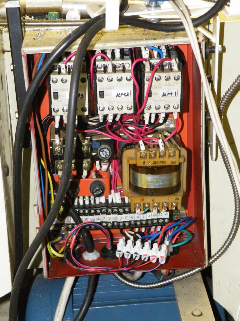
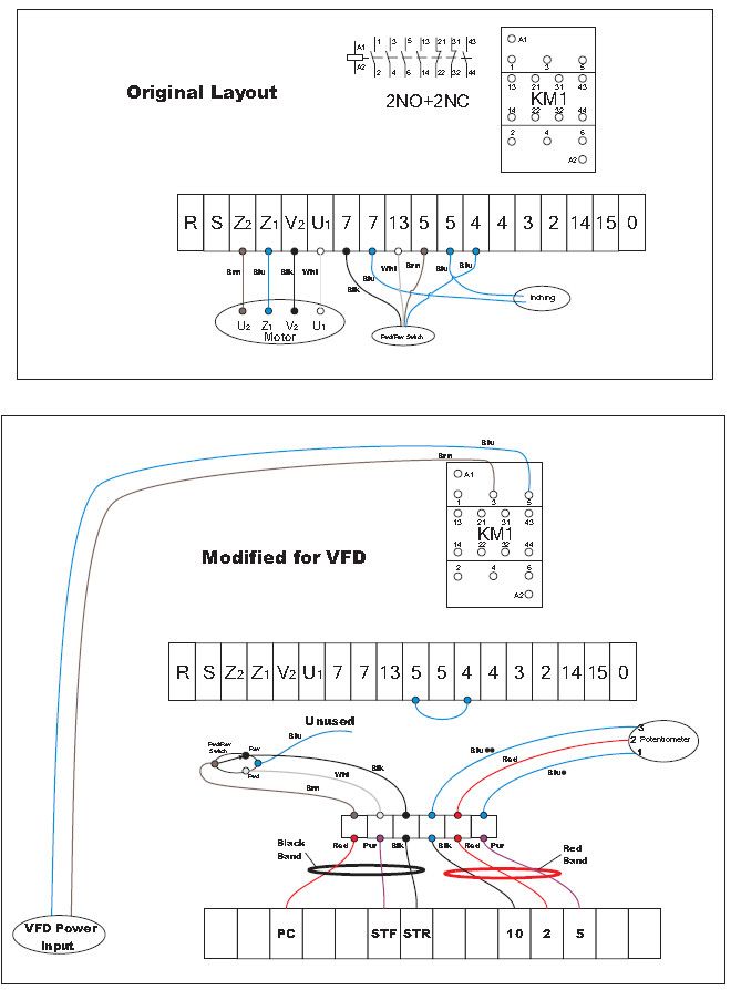
3 phase motor connection plate
3 phase motor connection plate
- This topic has 29 replies, 13 voices, and was last updated 31 October 2022 at 17:12 by
John Templeman.
- Please log in to reply to this topic. Registering is free and easy using the links on the menu at the top of this page.
Latest Replies
Viewing 25 topics - 1 through 25 (of 25 total)
-
- Topic
- Voices
- Last Post
Viewing 25 topics - 1 through 25 (of 25 total)
Latest Issue
Newsletter Sign-up
Latest Replies
- Boiler hydraulic test 4 hours
- Just How Many File Types Do We Need?
- MD65 leadscrew cross-slide stuck in nut
- Fobco or a Clarke CMD 1225 milling capabilities? or other recommendations?
- Arc Euro Trade Ltd.
- quality 3 and 4 jaw chucks
- Model Turbines
- Pragotron Slave Clock
- Miniature parts maker in Leicester?
- Pratt Bernard Grip true issues


