Crankshaft construction
Crankshaft construction
- This topic has 21 replies, 12 voices, and was last updated 9 November 2011 at 15:27 by
 Mike.
Mike.
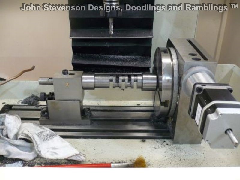


 ? I am building the Whittle V8 and after bending the crank 5 or 6 times in the lathe it got put on the back burner. The dummy ones where made from mild steel which may have been part of the problem, but having not done any engine building before probably contributed as well.
- Please log in to reply to this topic. Registering is free and easy using the links on the menu at the top of this page.
Latest Replies
-
- Topic
- Voices
- Last Post
-
-
Spindle/bearings fit query for X2 type mill
1
2
Started by:
fingerscrossed
in: Manual machine tools
- 14
-
8 July 2026 at 10:34
Graham Meek
-
Impending collapse in NYC
Started by:
Michael Gilligan
in: The Tea Room
- 5
-
8 July 2026 at 10:13
JasonB
-
When is a new 90 degree drill not 90 degrees?
1
2
Started by:
Bill Phinn
in: Workshop Tools and Tooling
- 15
-
8 July 2026 at 09:40
Mark Rand
-
24cc DIESEL ENGINE FROM SOLID
1
2
3
Started by:
dean clarke 2
in: I/C Engines
- 13
-
8 July 2026 at 09:35
KEITH BEAUMONT
-
Offen imperial bore mic gauge.
Started by:
Graeme Seed
in: Workshop Tools and Tooling
- 6
-
8 July 2026 at 09:28
alecs
-
Cotton-covered flex
Started by:
Kiwi Bloke
in: Materials
- 6
-
8 July 2026 at 08:27
bernard towers
-
Flat Surface
1
2
3
4
Started by:
COLIN MARTIN 2
in: Materials
- 36
-
7 July 2026 at 23:34
alecs
-
Hello from new USA member
Started by:
grizmaster
in: Introduce Yourself – New members start here!
- 3
-
7 July 2026 at 22:47
noel shelley
-
Mini-lathe parts source
Started by:
Dunc
in: General Questions
- 2
-
7 July 2026 at 20:37
JasonB
-
McLaren 1,5 inch scale Modl Traction Engine
Started by:
Mike Cooke
in: General Questions
- 1
-
7 July 2026 at 20:08
Mike Cooke
-
Flywheel material
Started by:
Speedy Builder5
in: Materials
- 8
-
7 July 2026 at 19:29
Speedy Builder5
-
Readability / clarity in new combined magazine
1
2
Started by:
Trevor Gale
in: Model Engineer & Workshop
- 19
-
7 July 2026 at 18:24
JasonB
-
Lathe coolant applicators
Started by:
lucerne
in: Manual machine tools
- 13
-
7 July 2026 at 17:32
JA
-
Myford Ml7 Technical Drawings
1
2
3
Started by:
Harry Broadbent
in: Model Engineer & Workshop
- 29
-
7 July 2026 at 14:02
Bazyle
-
1930 Austin 12 with 3rd brush dynamo
Started by:
john fletcher 1
in: General Questions
- 10
-
6 July 2026 at 22:07
Nimble
-
Identifying the pitch of threading inserts
Started by:
Bill Phinn
in: Workshop Tools and Tooling
- 6
-
6 July 2026 at 20:13
old mart
-
Valuatiion of severql models
Started by:
ron vale 3
in: Stationary engines
- 4
-
6 July 2026 at 19:23
Weary
-
Hi there fellow engineers
Started by:
ray1580
in: Introduce Yourself – New members start here!
- 6
-
6 July 2026 at 17:19
Howard Lewis
-
Hallo from Austria
Started by:
wilfried54
in: Introduce Yourself – New members start here!
- 4
-
6 July 2026 at 17:16
Howard Lewis
-
Jaxon Steam Car ride to the next 5 inch rail club
Started by:
Werner Schleidt
in: Traction engines
- 4
-
6 July 2026 at 17:11
Werner Schleidt
-
Unwanted Car Software Update
1
2
Started by:
Chris Crew
in: The Tea Room
- 19
-
6 July 2026 at 16:26
Bill Phinn
-
Accolade
Started by:
Bill Dawes
in: General Questions
- 8
-
6 July 2026 at 00:18
Nigel Graham 2
-
What Did You Do Today 2026
1
2
…
4
5
Started by:
JasonB
in: The Tea Room
- 36
-
6 July 2026 at 00:13
Nigel Graham 2
-
Laser centre finder
1
2
Started by:
Buffer
in: General Questions
- 16
-
5 July 2026 at 21:54
Vic
-
Brass covered steel
Started by:
Dougie Swan
in: General Questions
- 9
-
5 July 2026 at 20:43
Dougie Swan
-
Spindle/bearings fit query for X2 type mill
1
2
Latest Issue

Newsletter Sign-up
Latest Replies
- Spindle/bearings fit query for X2 type mill
- Impending collapse in NYC
- When is a new 90 degree drill not 90 degrees?
- 24cc DIESEL ENGINE FROM SOLID
- Offen imperial bore mic gauge.
- Cotton-covered flex
- Flat Surface
- Hello from new USA member
- Mini-lathe parts source
- McLaren 1,5 inch scale Modl Traction Engine

