Woody but not quite a Forest

Advert

Woody but not quite a Forest

Home Forums Work In Progress and completed items Woody but not quite a Forest

Viewing 15 posts - 1 through 15 (of 15 total)
  • Author
    Posts
  • #31261
    JasonB
    Moderator
      @jasonb
      Advert
      #413429
      JasonB
      Moderator
        @jasonb

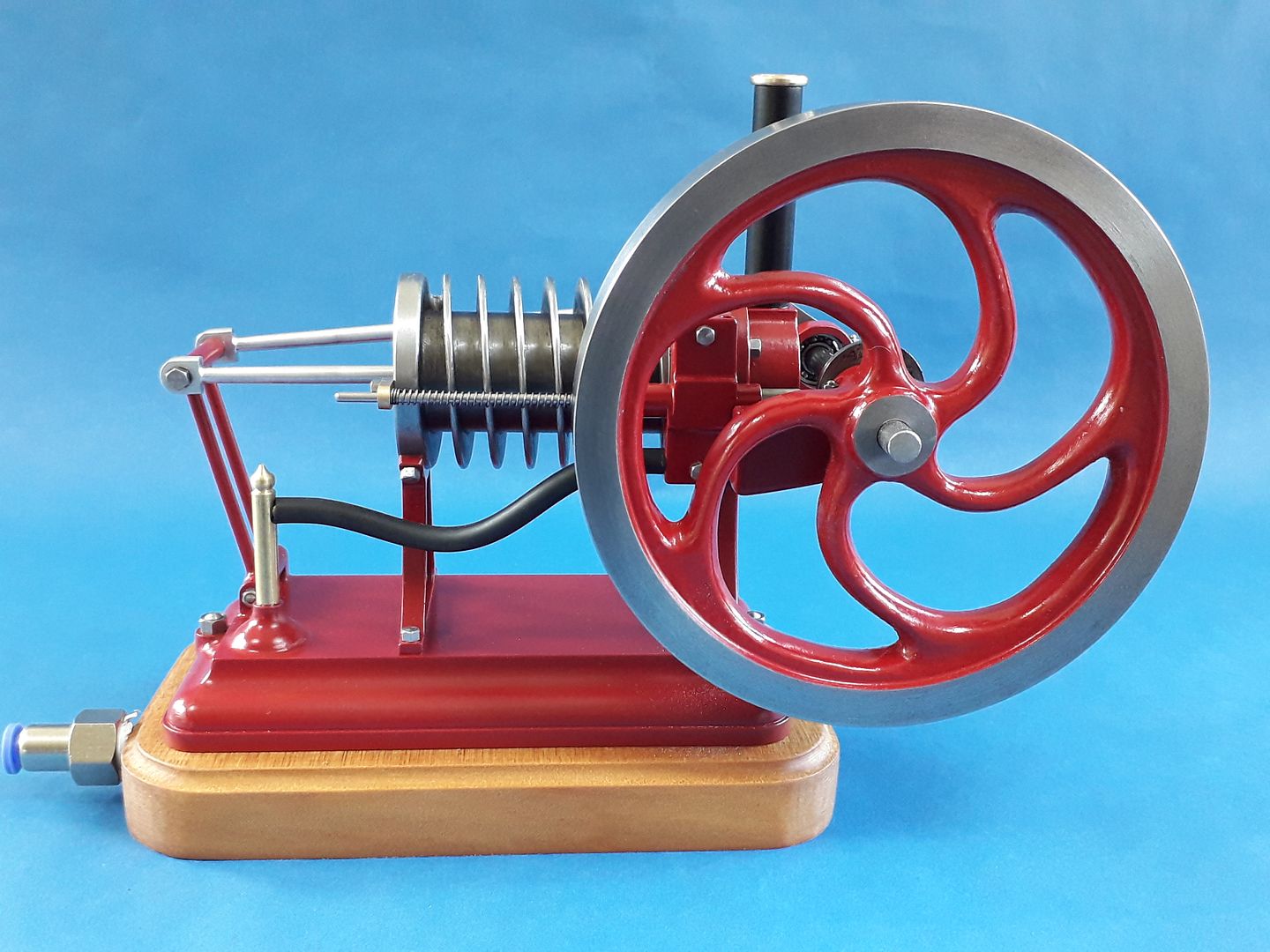
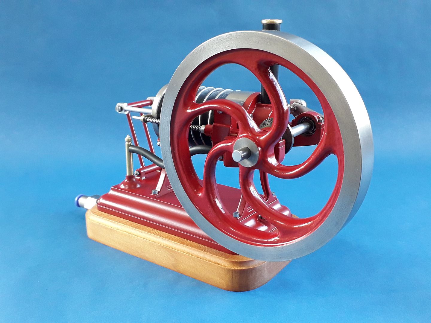
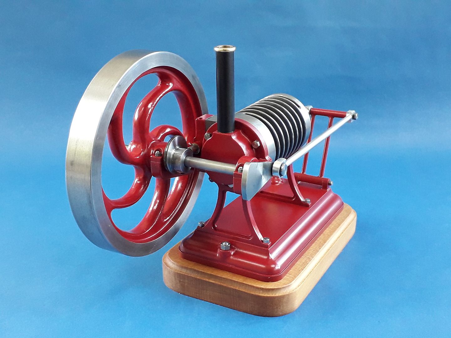
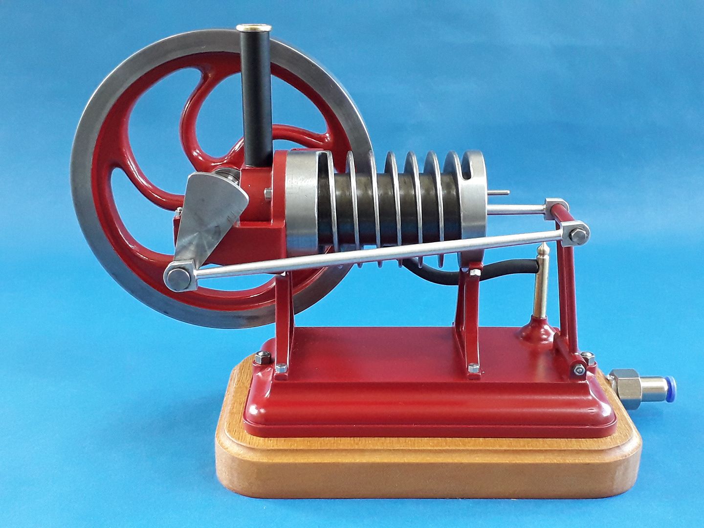
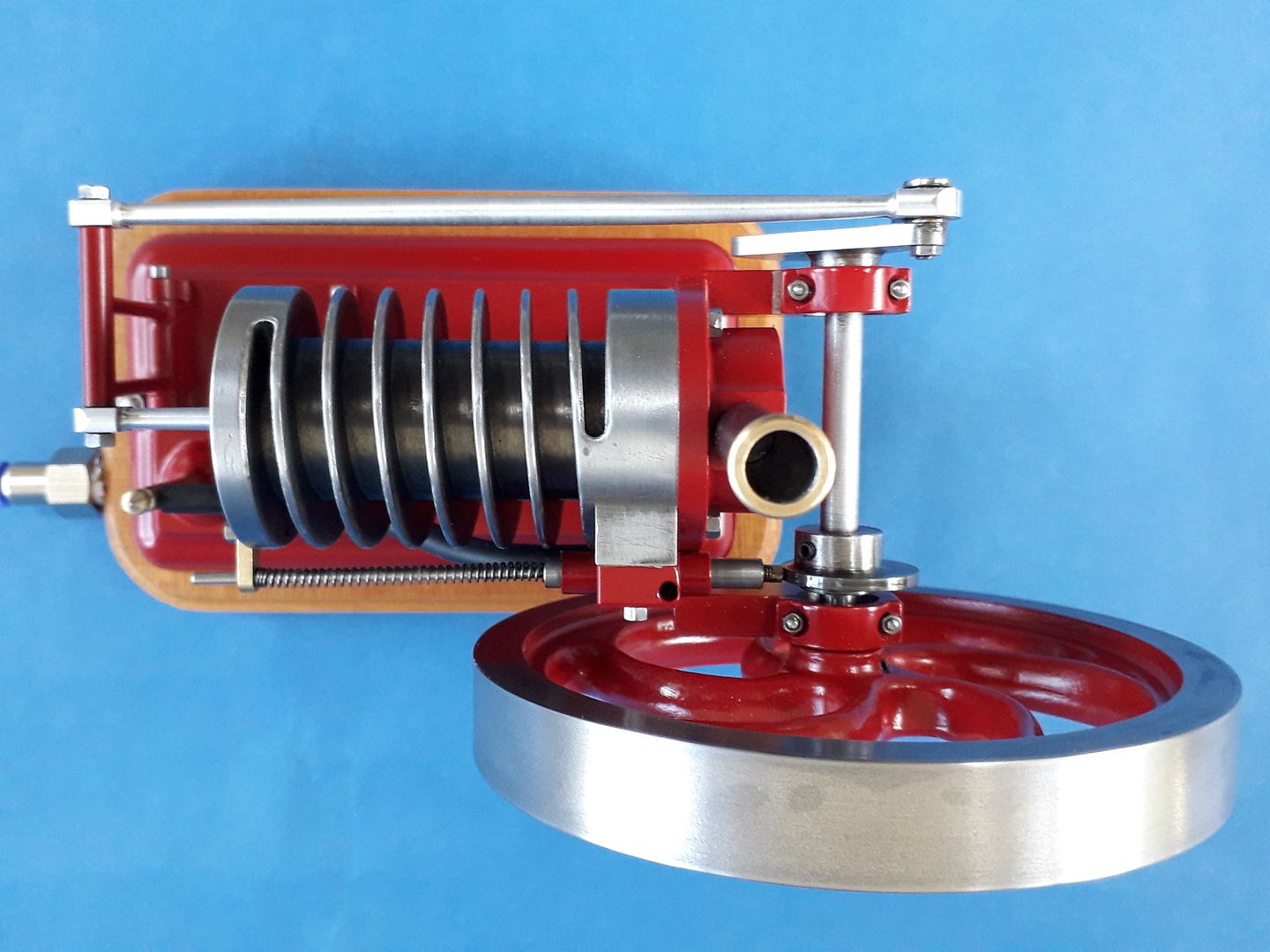
        I have always liked the look of the Forest engine reproductions that Wayne Grennings produced and thought that I might have a go at a smaller one myself. Chances of getting the non compression carrier flame ignition to work at the smaller sizes even if I could make up a suitable cocktail of gasses was slim but I thought it may work as a flame licker using the proven mechanicals of my Chuky and Alyn Foundries Chuk as a basis.

        Graham from Alyn had said that it would not be easy and he was right, I could not get it to run due to a few factors. Firstly the Evan's beam linkage of the crankshaft adds more drag, you can't easily get a clean flame with the shutter rods etc directly above and the biggest problem was with the can being so close to the shutter it tended to push it off the port face.

        I had always had it in the back of my mind that if I could not get it to run as a flame licker it may be possible to convert to an air/steam engine with poppet valves much like the Jowitt engine I made a while ago. Even this was going to be difficult due to the lack of room so a couple of weeks ago I decided that a spool valve may work and made up the various part which resulted in a running engine.

        It will run even slower than this but starts to get a bit jerkey as it is only single acting, at this speed it will run for at least 20mins on my small compressor without the tank needing to refill so not too noisy to run. It was an interesting project with a few more first crossed off the list such as first spool vale, first Evans bean and first spiral cooling fins.

        J
        #413439
        mechman48
        Participant
          @mechman48

          Verrrrrry nice little engine, well done that man, a round of applause I think.

          George.

          #413442
          AJW
          Participant
            @ajw

            Poetry in motion! Cracking looking engine, and my favourite, a nice slow Rickover.

            Great job.

            Alan

            #413615
            JasonB
            Moderator
              @jasonb

              Thanks for all the comments, on with the build.

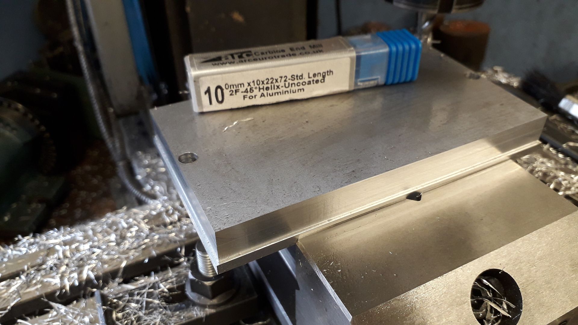
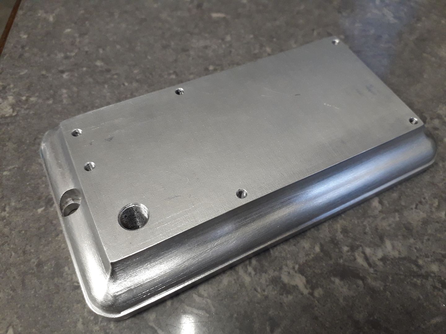
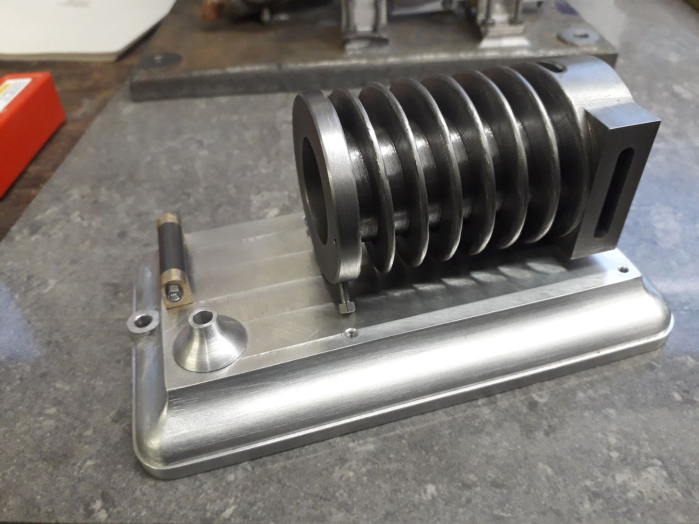
              The base plate was bandsawn from some 16mm 6082 plate and the two long edges flycut to size. Then with the plate held horizontally in the vice the two ends were squared up.

              Then a full 12mm height x 1mm deep pass all around formed the rebate, I used a 2-flute aluminium specific cutter which gave a nice finish.

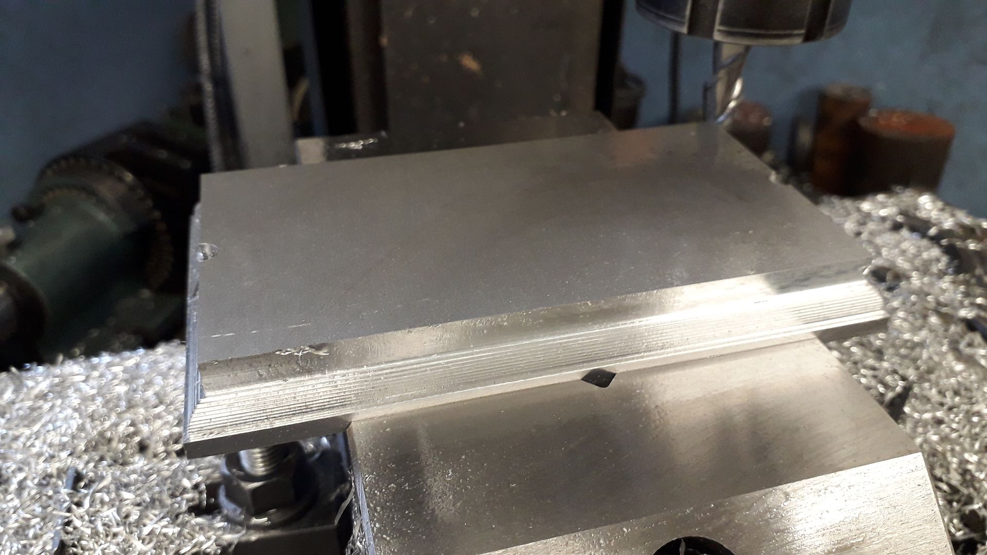
              Then using a set of co-ordinates taken from my Alibre drawing the convex part of the ogee moulding was cut in 0.5mm vertical increments around the four straight edges

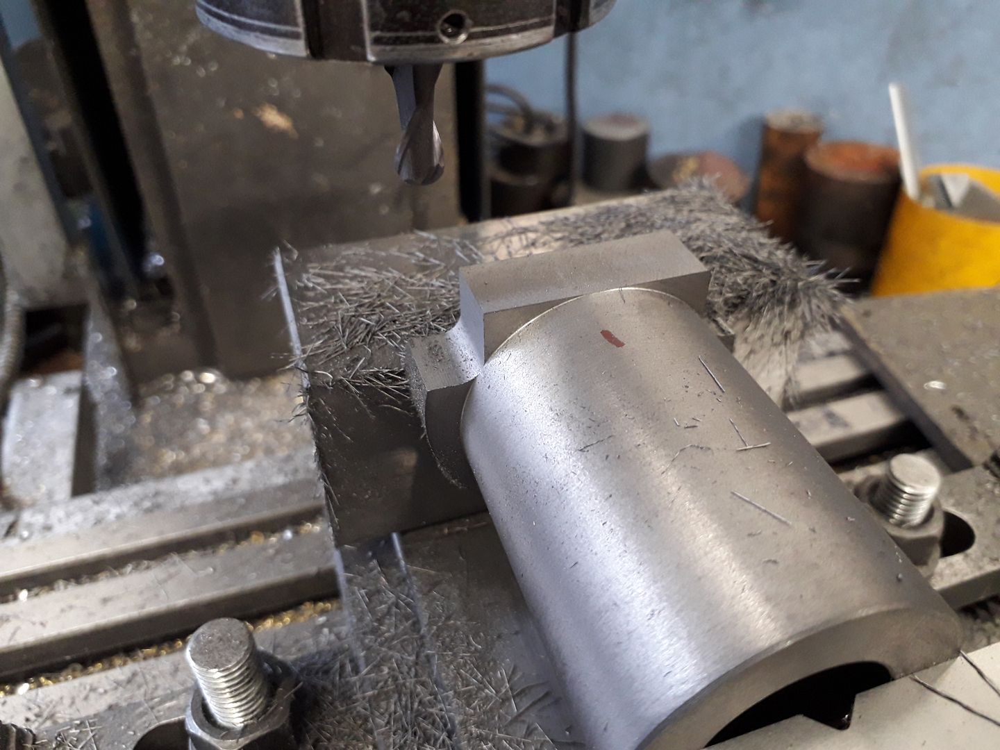
              Luckily I had a ball nose cutter which meant that the concave part of the moulding was a lot quicker to cut.

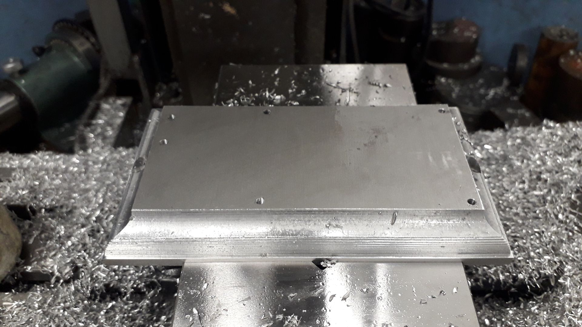
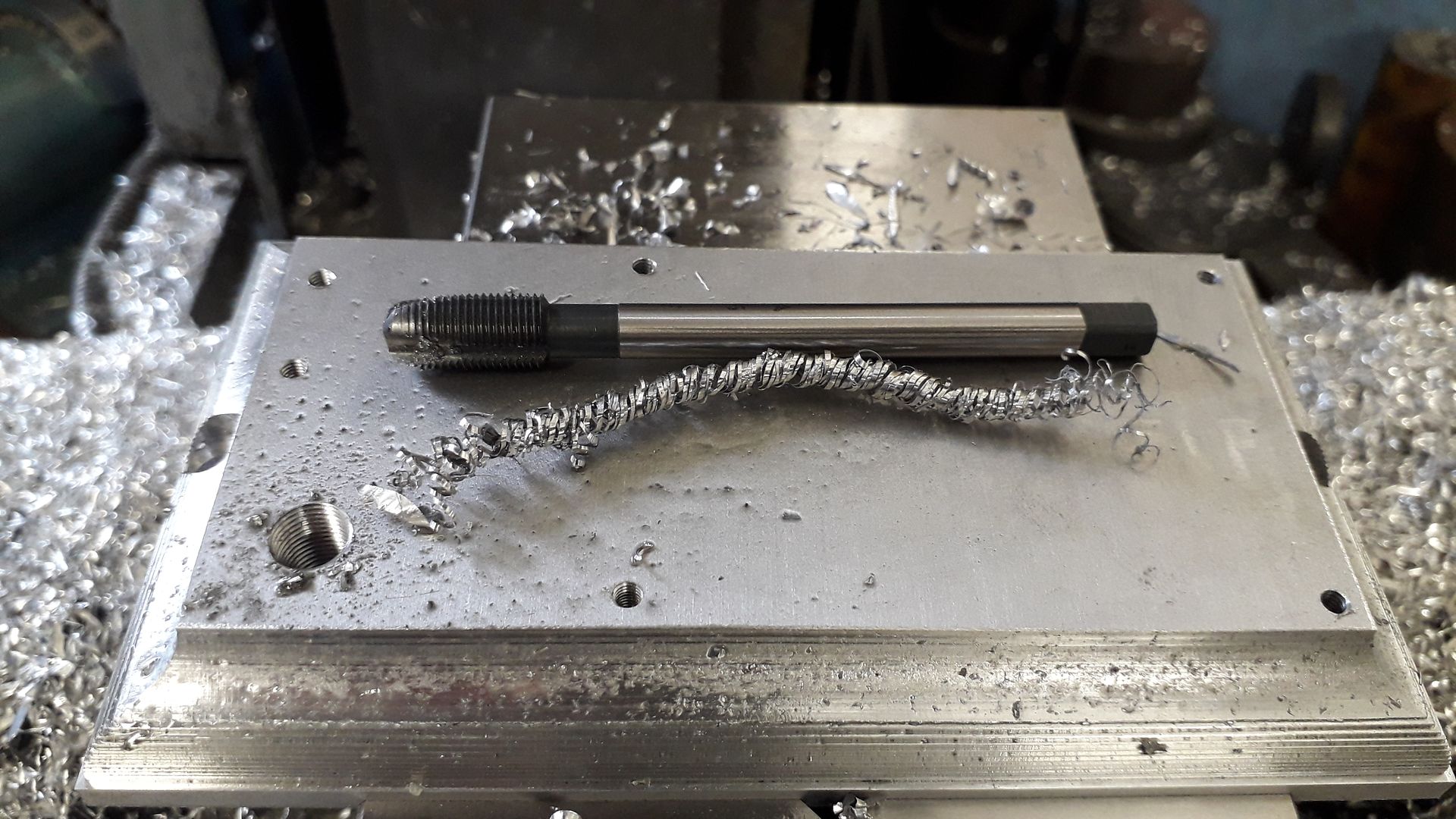
              While still in the vice the various holes were drilled and tapped, the smaller blind holes with a spiral flute tap and the M8x1 through hole with a spiral flute which just pushed the long spirals of swarf out the bottom of the hole and no need to keep backing off the tap to break the chips.

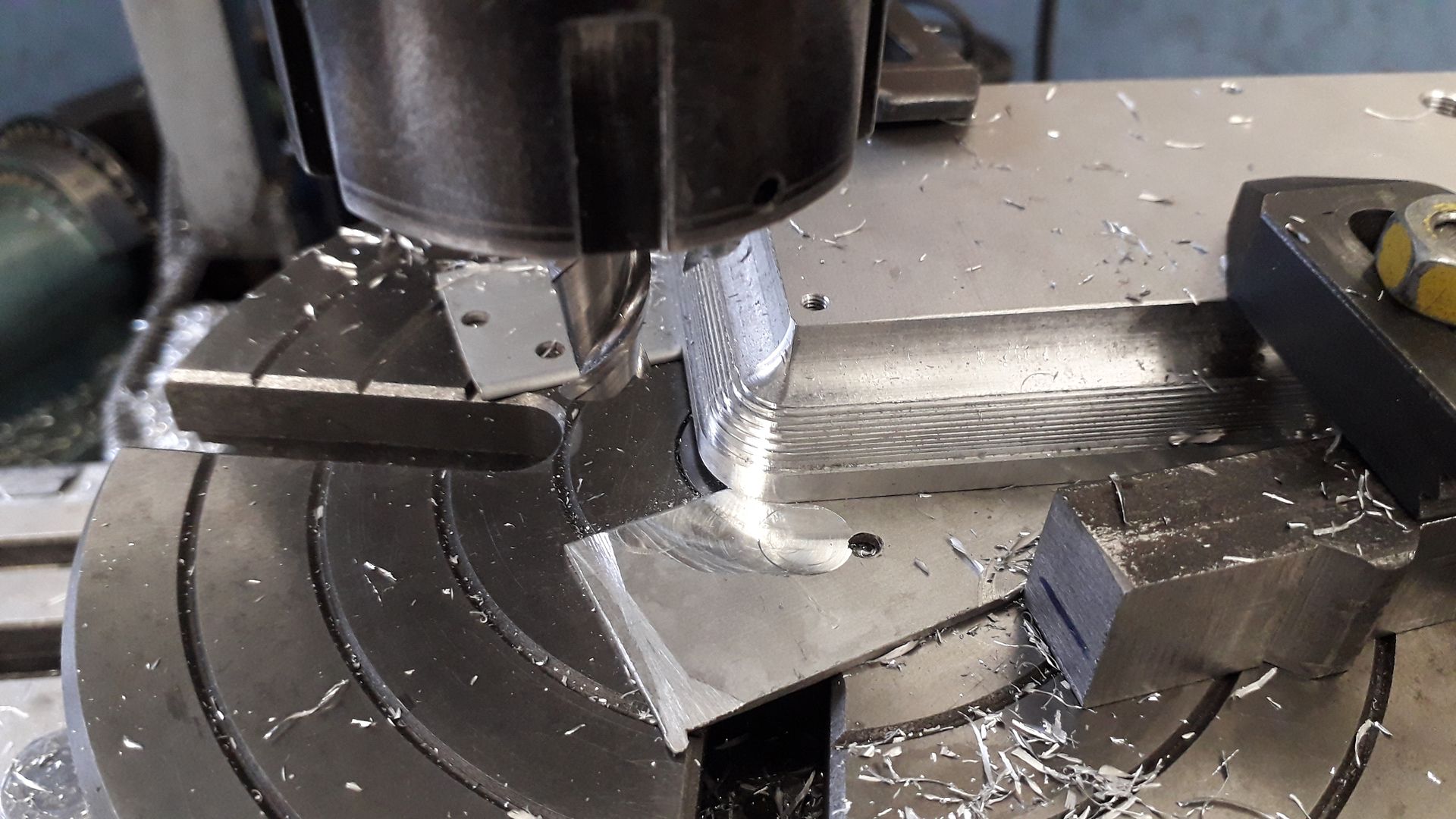
              The base was then transferred to the rotary table to round and mould the corners, I decided to do every other cut on these.

              It was then just a case of blending the stepped cuts into a nice flowing shape with files followed by some Emery cloth.

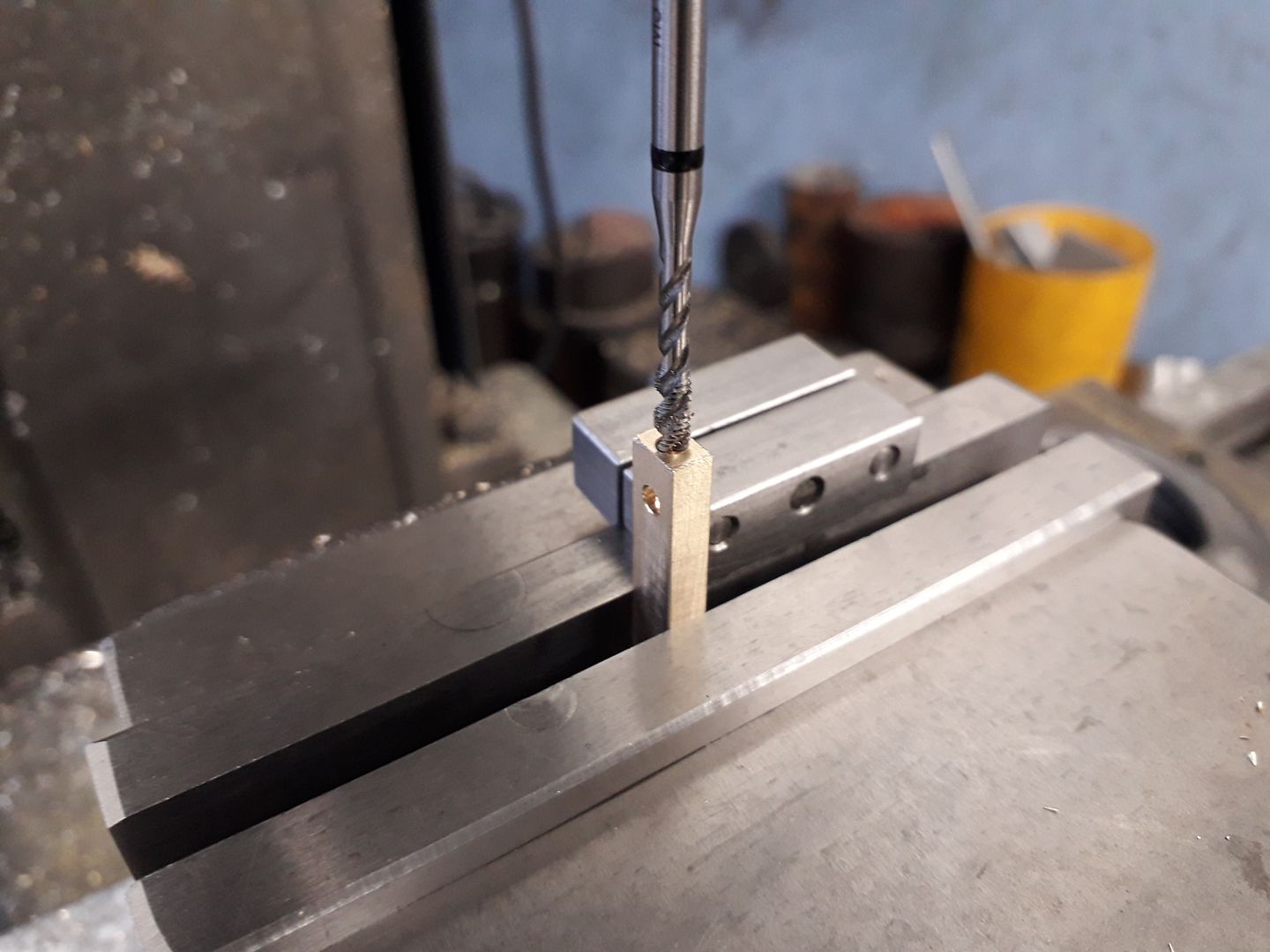
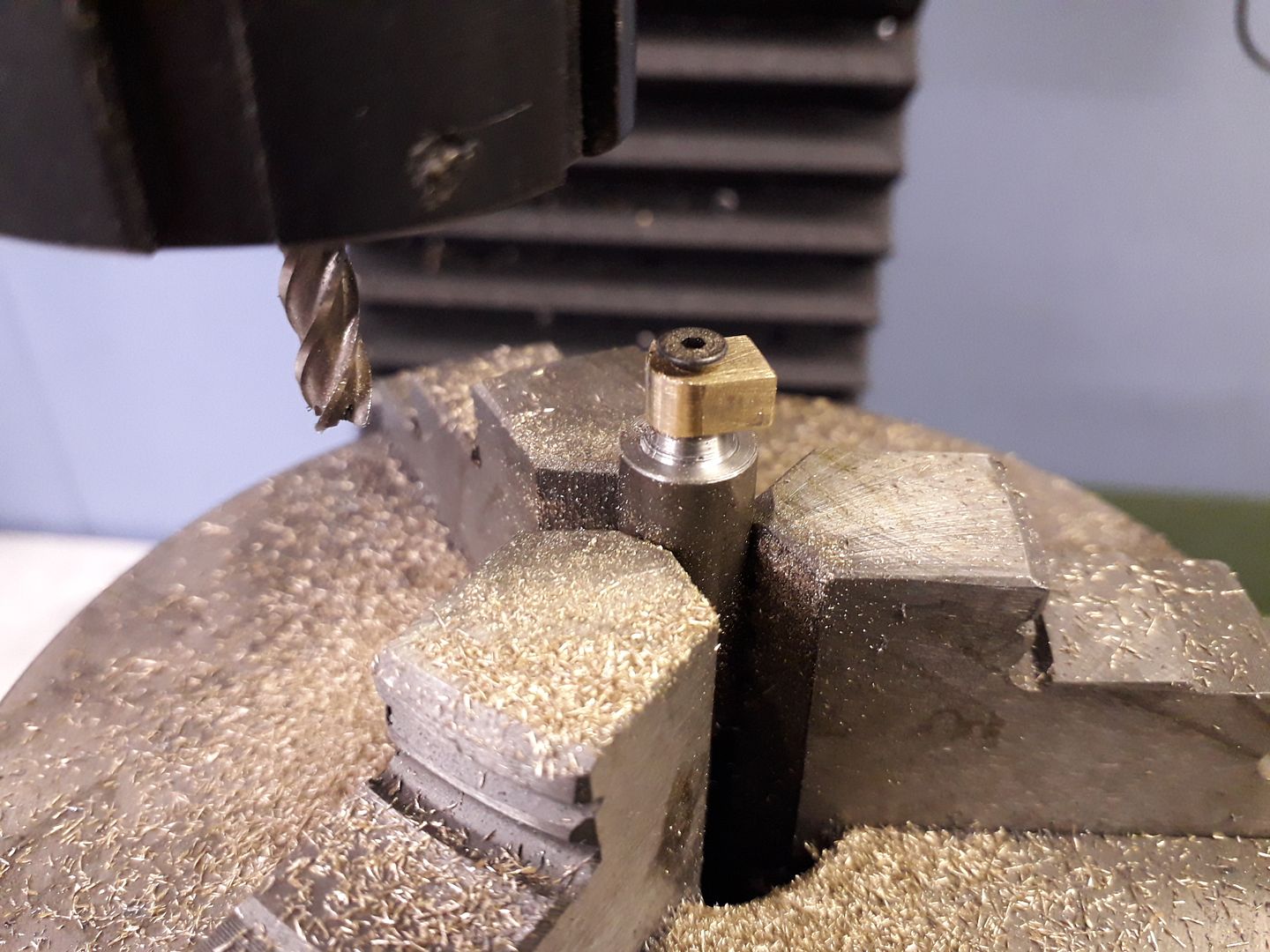
              The two lugs for the Evans beam to pivot on were worked onto either end of a small length of brass.

              Then sawn off and rounded over, again on the rotary table.

              #413949
              JasonB
              Moderator
                @jasonb

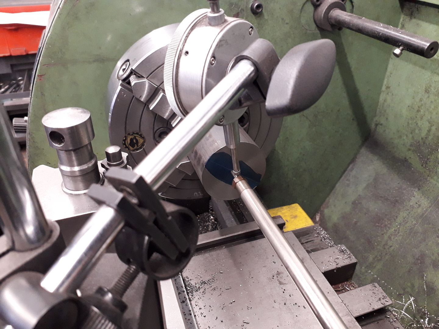
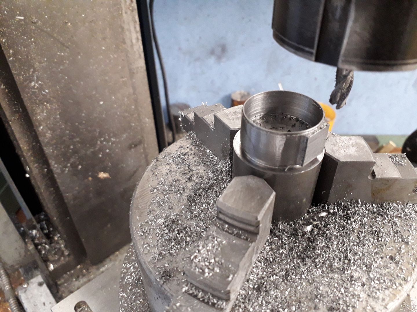
                The cylinder started out in much the same way as the Chuky with the ctr mark of the bore in the 50mm cast iron bar set to run true.

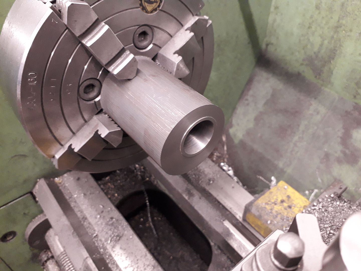
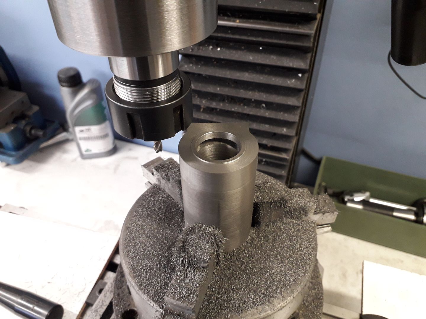
                It was then faced, bored and a small spigot added to locate the cylinder head.

                Reversed in the chuck the OD of the finned area was turned round and the end gently faced once the tailstock support had been removed.

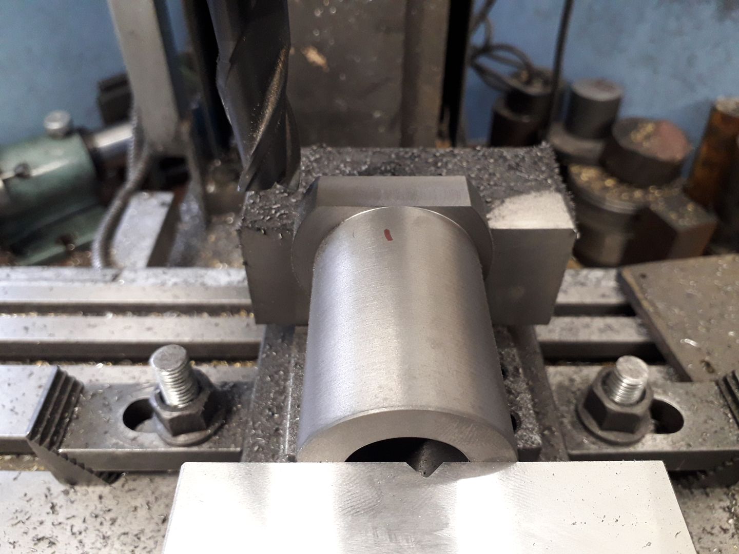
                Over to the mill and the port face was machined flat

                Then to width

                Followed by milling the port, this was sized for the flame licker version but could have been a lot smaller for the air/steam engine. I also had to subsequently drill and tap two M2.5 hols for the new valve block.

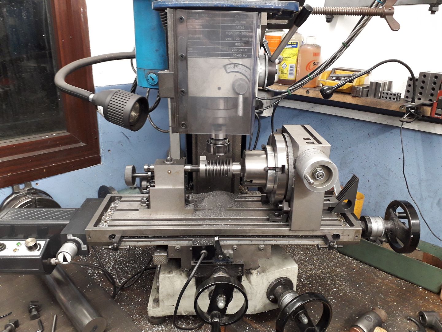
                With a change to the horizontally mounted rotary table the rest of the lower part of the cylinder was milled round.

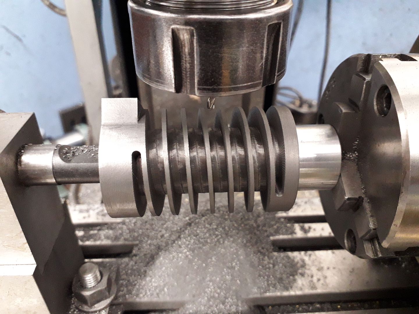
                Now for the fun part of machining the spiral cooling fins. The rotary table from ARC has a 72:1 reduction so for ease of machining I opted for a 7.2mm pitch spiral which meant that for every turn of the hand wheel the milll table would need to move 0.1mm, as this was a bit coarse I opted for half a turn of the handle and 0.05mm x-axis feed per plunge cut of a 5.5mm 3-flute cutter. The two ends of the spiral were feathered out further with a 3.0mm cutter.

                Just over 1000 plus plunge cuts later this is what I ended up with.

                This picture shows the machining marks left by the plunge cuts which were cleaned up with a file and the whole "casting" given a once over with the Dremel to give it that cast look.

                I think it could do with some legs next

                #413957
                Boiler Bri
                Participant
                  @boilerbri

                  I like the cylinder, did you try screw cutting it first or was the milling the first option?

                  B

                  #413961
                  JasonB
                  Moderator
                    @jasonb

                    Did not consider screwcutting as I woud not have been able to start and stop without run in/out grooves and approx 3.5TPI is beyond my machine.

                    I did briefly consider mounting my old Unimat 3 mill column on the lathe cross slide but by the time I had done that and sorted out gears and a leadscrew drive the mill was the easier option.

                    #414028
                    Ron Laden
                    Participant
                      @ronladen17547
                      Posted by JasonB on 12/06/2019 19:36:15:

                      Now for the fun part of machining the spiral cooling fins. The rotary table from ARC has a 72:1 reduction so for ease of machining I opted for a 7.2mm pitch spiral which meant that for every turn of the hand wheel the milll table would need to move 0.1mm, as this was a bit coarse I opted for half a turn of the handle and 0.05mm x-axis feed per plunge cut of a 5.5mm 3-flute cutter. The two ends of the spiral were feathered out further with a 3.0mm cutter.

                      Just over 1000 plus plunge cuts later this is what I ended up with.

                      Jason, you must have the patience of a Saint, over 1000 plunge cuts…surprise you should be awarded a medal for that..smiley

                      #414068
                      Nigel Graham 2
                      Participant
                        @nigelgraham2

                        Superb work – challenging too, and I noticed something I suspect many of us (mea culpa!) overlook – close attention to cutter and tap types best suited to operation and material.

                        I'm a bit puzzled: You did not link the table travel to rotation, for what is effectively thread-milling, by gearing or digital control? So all by manual travel / angle setting? If so, as Ron says, the patience of a saint!

                        '

                        I recall some years ago an ME contributor saying faced with an equally repetitive operation, thinking it best he did just a few increments a day to keep up the standard. He was filing the triangular ports in locomotive piston-valve liners, where obviously the lengthways extremities matter. He told us he would get up a bit earlier in the morning and file two or thee of the already-drilled holes before going to work, leaving the next two or three till next day. After all, there was plenty of other work on the project for the evenings.

                        #414072
                        JasonB
                        Moderator
                          @jasonb

                          Ron you may just be able to see my hitec depth stop at the top of the photo, that did help a bit.

                          Nigel, My mill does not have the facility to gear the table movement to the dividing which would have been another way to do it. I did consider putting my old Unimat3 milling column on the lathe carrage and setting up to "screwcut" but I would have needed to buy or make extra gears and probably drive the leadscrew as the 3.5tpi pitch is too coarse.

                          I have since got a CNC mill which with the addition of a 4th axis would have been an ideal way to cut the spiral and the basic machine would be what I would use now to machine the baseplate. Luckily I am able to draw the parts in 3D which is the starting point for CAMwink 2

                          #414075
                          Nigel Graham 2
                          Participant
                            @nigelgraham2

                            Thank you Jason, for the explanation.

                            "Wink" indeed…..

                            You raise a point I've wondered for a while.

                            We all know conventional screw-cutting on the lathe, a thread coarser than the lead-screw is very unfair to the machine; but does that apply to thread-milling? I'm assuming light cuts of course.

                            It would also need thought about the thread-ends: whether a radial run-out groove would be acceptable or you the spiral needs a "sudden" end as on this engine. The latter probably would involve disconnecting the normal drive and turning the lathe by hand, from either the spindle or the lead-screw.

                            If rapid-lead threading is possible in this way, it should not be too difficult to produce not only coarse multi-start single-way threads, but also single-start reversing-screws. (The motion is carried by a circular pin or lozenge-shaped follower.)

                            #414077
                            JasonB
                            Moderator
                              @jasonb

                              For proper thread milling where a rotating cutter follows a helical path into the hole or around a cylinder the limiting factor will be the clearance angle of the cutter so it does not foul the helix.

                              If milling with a setup like I used but with a driven axis at right angles to the spindle then there is no limit to pitch, just use the correct feed rates for the tool. If you have a google for "router lathe" you will see they can cut a very quick helix.

                              Yes a reversing screw or cam would be possible as would variable pitch screws, helical and worm gears.

                              #414131
                              JasonB
                              Moderator
                                @jasonb

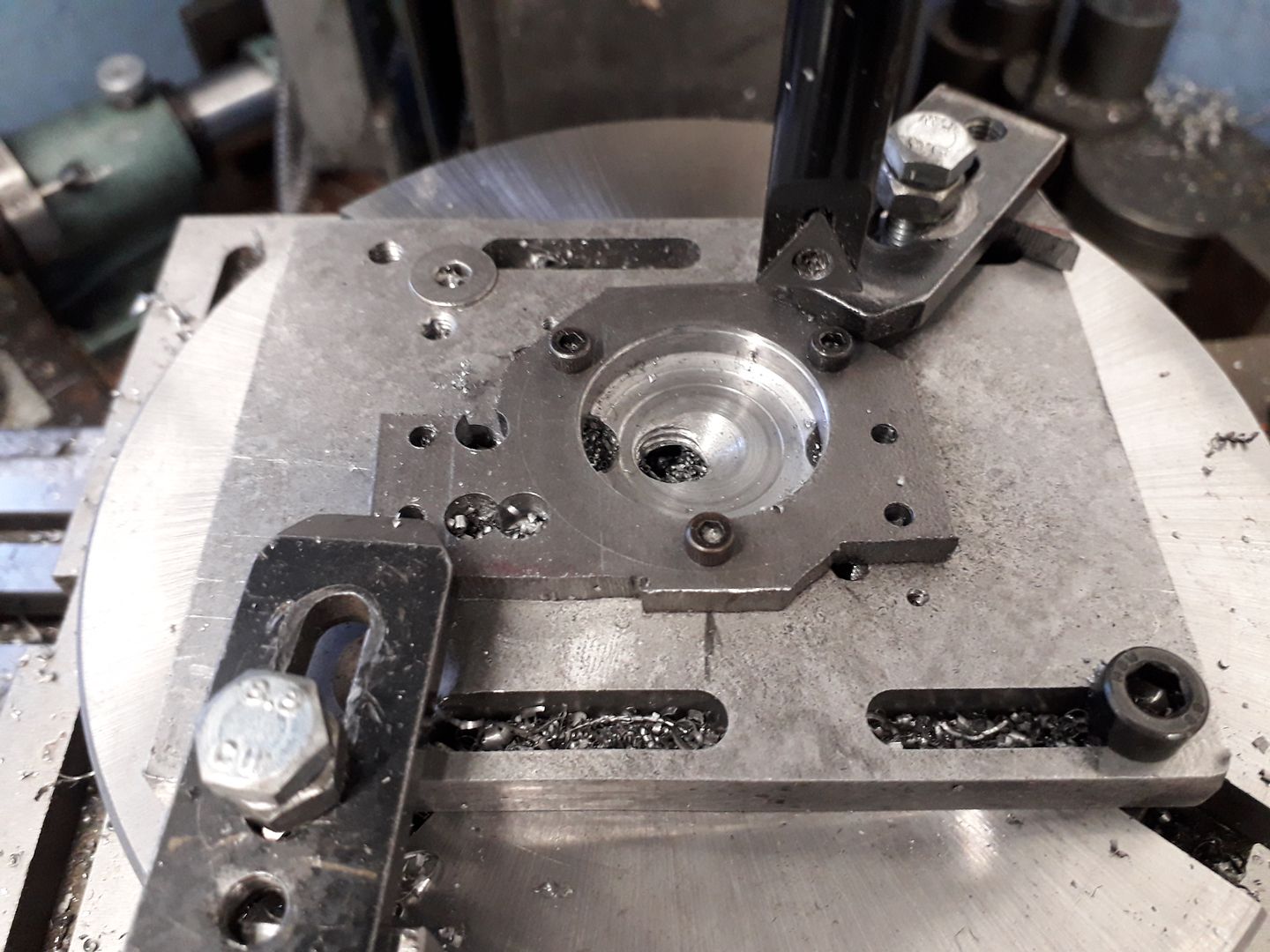
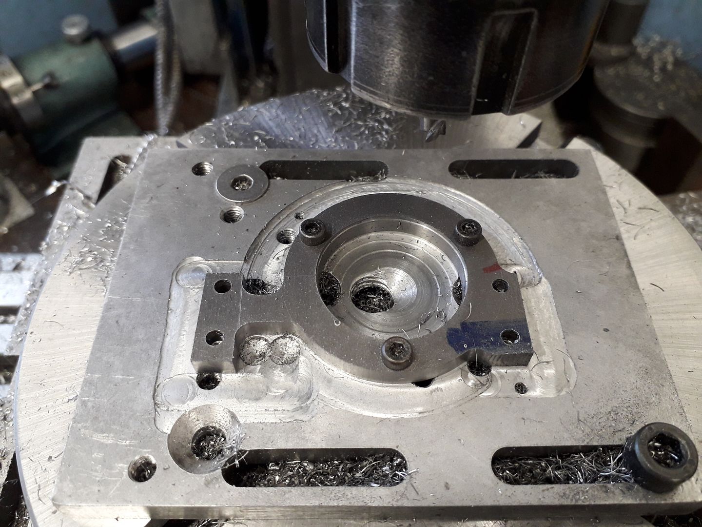
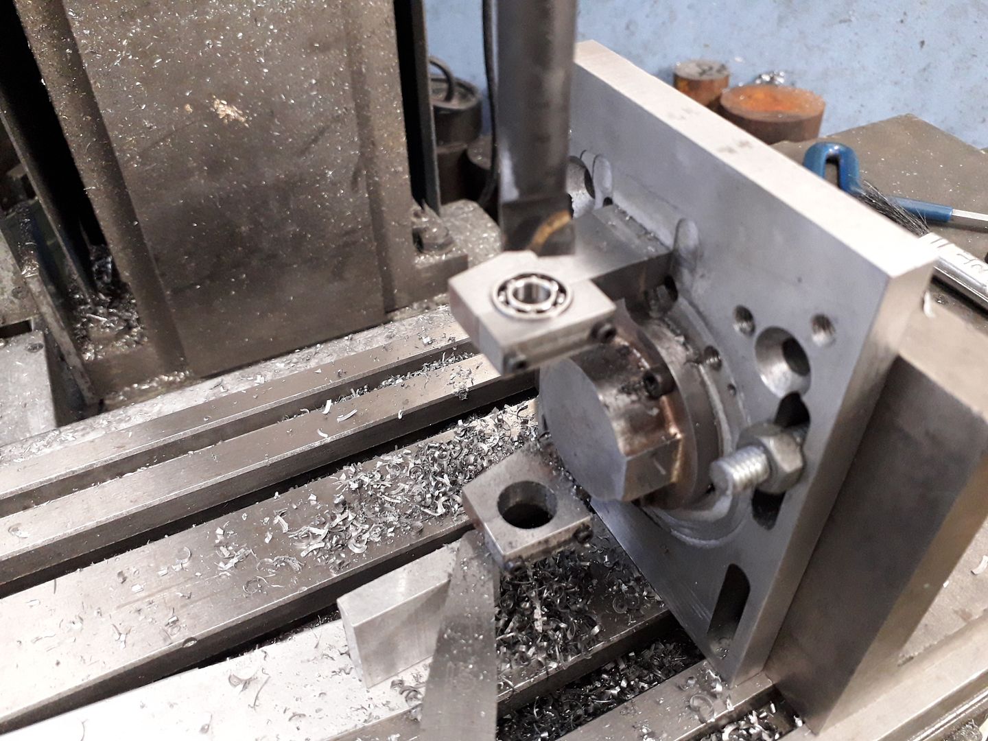
                                The "cylinder head" which incorporates the bearing supports started life as a piece of 5mm plate which was marked out and the bigger bits of waste material roughly sawn off. This was then clamped to a scrap of aluminium on the rotary table for drilling the various small holes and some to define the internal corners. Three of the holes were carried on at tapping size into the ali plate and then tapped so some additional screws could be used to hold the part while the main hole was bored.

                                The two clamps were then removed and the outside milled to shape.

                                The flame licker design needed a chamber for the spring and valve, this was bored out on the lathe and then transferred to the mill to shape the outside leaving a flat area into which the exhaust stack would screw.

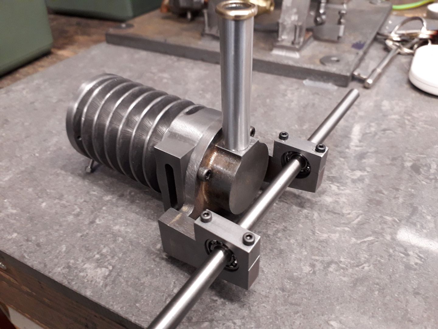
                                Jumping forwards a bit the parts including two bearing supports have been silver soldered together, bearing caps screwed on and the assembly mounted back onto the ali plate to bore first the top bearing hole.

                                And then the other, in both cases the bearing was used to gauge the size of the hole

                                Hard to resist a quick trial fit

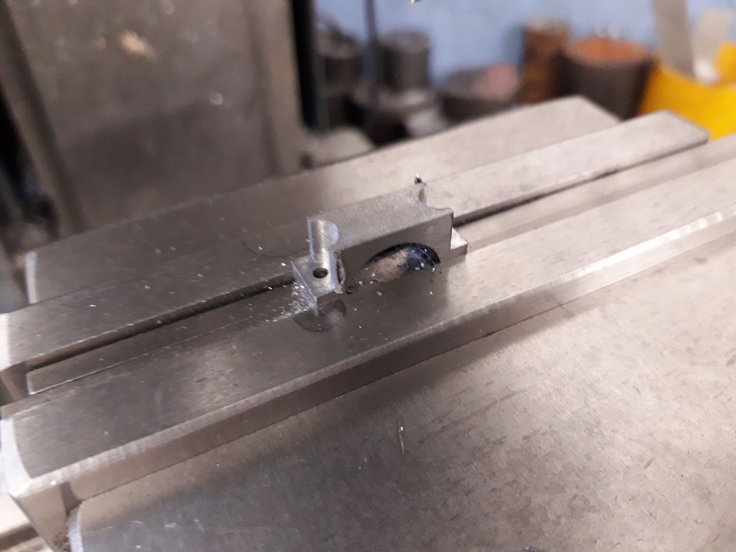
                                A bit of milling and the bearing caps start to take shape

                                Then roughing out the curved top which was finished off with a file

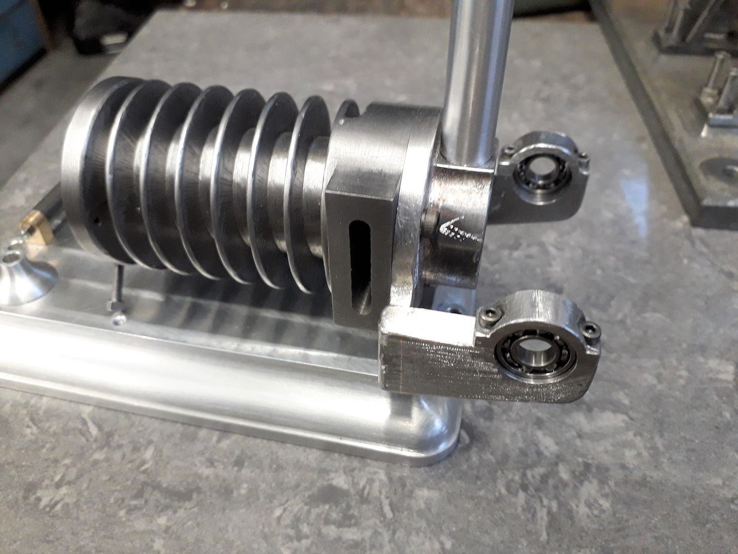
                                Final bit of machining was to drill and tap two radial holes for the legs to fix to.

                                A quick talking to with a grinding point in the Dremel knocked off all the hard corners and added a bit of texture to get the cast look.

                                #415786
                                JasonB
                                Moderator
                                  @jasonb

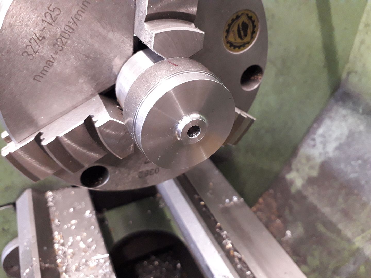
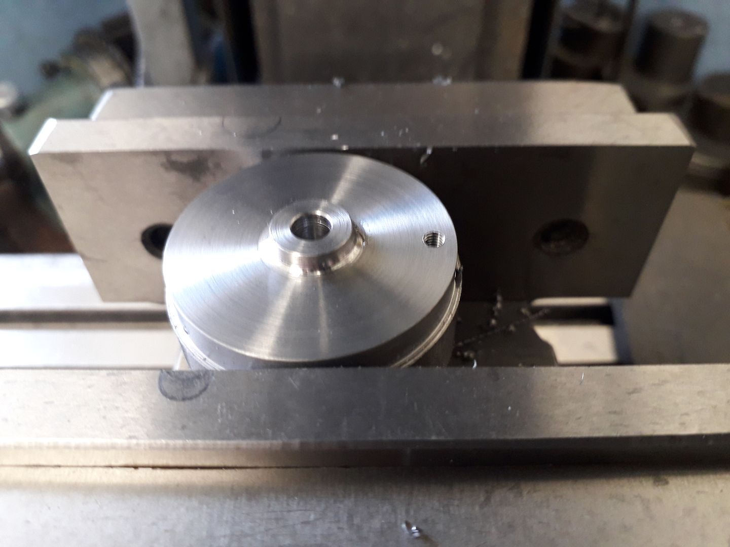
                                  The crank web was first turned from some 40mm bar.

                                  before transferring to the mill to drill and tap a hole for the crank pin, after which it was parted off a little over thickness and then milled to the counterbalanced shape.

                                  After Loctiting to the 6mm shaft the assembly was put back in a collet to machine the web to thickness, I like to do it that way so that the face the pin will tighten up to is at perfect right angles to the shaft axis even if the loctite joint had of been a bit off. The two other fittings were not needed for the air/steam version.

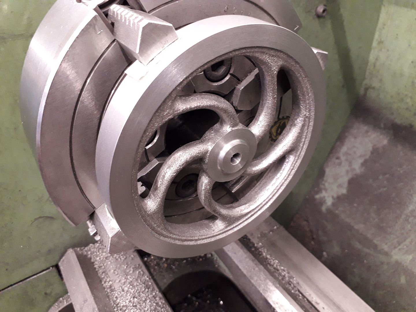
                                  Another curved spoke flywheel casting the same as I used on the Muncaster Entablature engine was soon machined up to a firm push fit on the crankshaft.

                                  Time for a quick play to see how the bearings from ARC run, i can't really complain about this.

                                  Edited By JasonB on 23/06/2019 20:15:54

                                Viewing 15 posts - 1 through 15 (of 15 total)
                                • Please log in to reply to this topic. Registering is free and easy using the links on the menu at the top of this page.

                                Advert

                                Latest Replies

                                Viewing 25 topics - 1 through 25 (of 25 total)
                                Viewing 25 topics - 1 through 25 (of 25 total)

                                View full reply list.

                                Advert

                                Newsletter Sign-up