Pinning topslide on ML7/Super 7

Advert

Pinning topslide on ML7/Super 7

Home Forums Manual machine tools Pinning topslide on ML7/Super 7

Viewing 25 posts - 1 through 25 (of 25 total)
  • Author
    Posts
  • #315140
    Clive Washington
    Participant
      @clivewashington54052

      When I acquired my ML7 many years ago, the first thing I did was to convert it to the Super 7 type of topslide which allows a full 360 degree rotation. However I've noticed a problem. Under moderate loading there is a tendency for the slide base to rotate gradually. I could lean on the clamping screws but this seems an inelegant solution.

      I was considering putting a pin, maybe a taper pin, through the topslide base into the cross slide. The idea being that you would accurately adjust the topslide to turn parallel and then pin it; so whenever you have the pin in place the slide will not rotate and will have been set to turn parallel. Of course you would have to remove it if you wanted a different angle, but most of the time the slide is used in the parallel position.

      Has anybody tried this, or perhaps could point out a downside that I've not noticed?

      Advert
      #13037
      Clive Washington
      Participant
        @clivewashington54052
        #315167
        Nick Hulme
        Participant
          @nickhulme30114

          Do you have the correct locking tapers in front of the screws?

          I don't have any creep problems with my Super 7,

          Regards,

          Nick

          #315174
          KWIL
          Participant
            @kwil

            They are left and right handed, I have no problems with rotational drift on my S7s

            #315179
            Clive Washington
            Participant
              @clivewashington54052

              Actually I don't have locking tapers (I assume you are talking about plugs that head up the grubscrews) as this is a DIY conversion. I just have two 0BA grubscrews bearing on the mounting cone. Could be I need more beef in this area. Would still be interested in opinions on the pinning idea though -if only to get a repeatable parallel reset on the topslide.

              #315184
              Chris Gunn
              Participant
                @chrisgunn36534

                Clive, taper pinning a swivelling head is common on industrial machines, so no reason why it would not work for you, I would suggest a taper pin with a male or female thread depending on diameter so you can extract it when required.

                Chris Gunn

                #315212
                Robbo
                Participant
                  @robbo

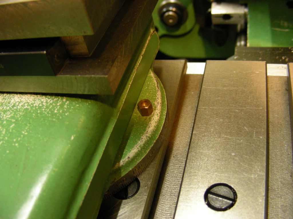
                  You mean one like this – has been on my 60 year old S7 for a long time. These days pliers are needed to remove it, hence gnarled appearance! The white bit is plastic channel to keep swarf out of the unused T-slot.

                  I would recommend you buy the proper tapered plugs to lock the topslide though.

                  Sorry, should have made the picture smaller.

                  dscn5859.jpg

                  Edited By Robbo on 04/09/2017 19:31:59

                  #315214
                  KWIL
                  Participant
                    @kwil

                    0BA grub screws pressing against the taper cone is a certain way to ruin it and chewing up the surface. You have little or no bearing surface you are pressing upon, hence movement. With the right use of the locking tapers in front of the screrw, you have considerably more area to press against.

                    #315243
                    Clive Washington
                    Participant
                      @clivewashington54052

                      Fortunately the cone shows little sign of damage. I wonder if the angular plugs are still available? I was thinking of exactly the setup in Robbos picture for the pin.

                      #315249
                      Robbo
                      Participant
                        @robbo

                        The plugs are available from Myford – **LINK** for the right hand one – don't forget they are handed left and right.

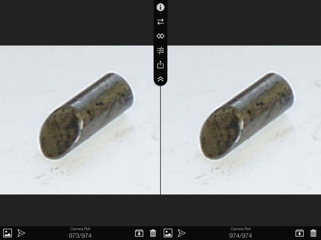
                        Probably just as effective would be a bit of brass round bar, say 3/4" long of 3/8", with the end cut off at a 60 degree angle. But is it worth the trouble at the price?

                        #315275
                        Clive Washington
                        Participant
                          @clivewashington54052
                          Posted by Robbo on 05/09/2017 00:04:42:

                          Probably just as effective would be a bit of brass round bar, say 3/4" long of 3/8", with the end cut off at a 60 degree angle. But is it worth the trouble at the price?

                          It certainly is…

                          #315279
                          Michael Gilligan
                          Participant
                            @michaelgilligan61133

                            O.K. … I have to ask:

                            Is there really a difference between the Left and Right versions of this item

                            … or is it like having a left-handed teacup. question

                            Myford lists two items, and uses pictures with different file-names

                            … but the two images are visually identical.

                            MichaelG.

                            [with an ML7R, so innocent in the ways of Super 7]

                            .

                            img_1401.jpg

                            Edited By Michael Gilligan on 05/09/2017 08:17:18

                            #315282
                            Clive Washington
                            Participant
                              @clivewashington54052

                              That did occur to me.. The problem with the brass plugs is that, if you want to remove the topslide, they don't retract with the screws and the whole thing has to be wobbled and shaken until they decide to get out of the way.

                              #315286
                              Ex contributor
                              Participant
                                @mgnbuk

                                Be wary of overtightening the standard Super 7 arrangement. The cross slide is weak at the point where the clamp holes intersect the top slide bore. On the 2 Super 7s I have had, both cross slides were bent at that point & required regrinding.

                                I only apply a slight nip to the clamp screws after regringing the cross slide to try & prevent a repeat & have not had an issue with the top slide moving under load.

                                It has been a while since I had mine apart, but I seem to recall that the ends of the clamp pads are cut differently – the use of one photo for two part listings is probably laziness, as the original Super 7 parts list has them as different part numbers and describes them as handed.

                                Nigel B

                                #315287
                                Martin Kyte
                                Participant
                                  @martinkyte99762

                                  This is an interesting problem. My take on it would be that the original system of the screw clamps acting on bevel faced plugs draws the topslide down onto the surface of the cross slide an thus clamps it. With direct contact screws the action is more of 'nipping the' 45 deg taper of the topslide base especially after dimples have developed in it. Depends a little on the shape of the screw clamp ends. I would concur with some of the above suggestions that the way forwards is to complete the mod with the addition of the proper plugs. The other area for examination is the bearing surface on the underside of the topslide. In the course of things it will wear most towards the outside and eventualy end up round bottomed. This has the result of the clamping force being mainly in the centre where they have the least effect. Bluing the base will reveal this and a quick skim or even a spell with a scraper will rectify this.

                                  regards Martin

                                  #315298
                                  Robbo
                                  Participant
                                    @robbo

                                    "Is there really a difference between the Left and Right versions of this item"

                                    Yes there is. Not visible in photographs, (and even difficult to see when you've got one in your hand) but there is a slight curve across the face of the plug, slightly diagonally, so that it seats on the topslide spigot properly. So the diagonal on the left hand is opposite to the one on the right hand. Because of the taper on spigot and plug the plug not only presses against the spigot but draws it down so the topslide is pressed against the crossslide.

                                    What looks like a simple plug is quite cleverly thought out.

                                    "Myford" descriptions are not the most accurate since they became a branch of RDG, so they may have used the same image.

                                    Edited By Robbo on 05/09/2017 09:38:33

                                    #315299
                                    Michael Gilligan
                                    Participant
                                      @michaelgilligan61133
                                      Posted by Nigel B on 05/09/2017 08:40:06:

                                      … It has been a while since I had mine apart, but I seem to recall that the ends of the clamp pads are cut differently – the use of one photo for two part listings is probably laziness, as the original Super 7 parts list has them as different part numbers and describes them as handed.

                                      .

                                      Thanks for that, Nigel [and Robbo]

                                      … it says a lot.

                                      MichaelG.

                                      Edited By Michael Gilligan on 05/09/2017 09:39:06

                                      #315300
                                      speelwerk
                                      Participant
                                        @speelwerk

                                        Using an adaptor plate of the same dimensions as the taper cone of the topslide, the clamping force is strong enough to hold a swiveling vertical slide with dividing atachment in place. Usually the wheels I cut are small and this works better for me then clamping the vertical slide the normal way. Niko.

                                        Edited By speelwerk on 05/09/2017 09:47:21

                                        #315302
                                        ega
                                        Participant
                                          @ega

                                          Here is my version of the taper pinned topslide:

                                          dscn1408.jpg

                                          I think I got the idea from Sparey's excellent book but couldn't find the reference just now. My small taper pin is rather fiddly and I have been meaning to install a larger one (the "meat" here is rather limited, however).

                                          My machine is about the same age as Robbo's but is mutton dressed up as lamb; I went for Myford green when refinishing many years ago.

                                          I, too, think that the thrust pads are handed and made the point about not inadvertently swapping them in a post in an earlier thread. The pads contact the male taper at a tangent, as it were.

                                          Edited By ega on 05/09/2017 09:50:28

                                          #315315
                                          Clive Washington
                                          Participant
                                            @clivewashington54052

                                            I couldn't initially see why the thrust pads should be handed, even if they were curved to match the cone of the topslide. Then it dawned on me that the clamping screws might not intersect the cone bore at 90 degrees. As I said, my setup is a DIY conversion from the old ML7, and I arranged the clamping screws to be at 90 degrees to the cone, so the plugs would be identical. I copied this arrangement from my Perris SL90. It does result in the RH screw being tricky to access and perhaps the setup on the S7 (which I haven't examined closely) is a bit different.

                                            #315386
                                            larry Phelan
                                            Participant
                                              @larryphelan54019

                                              On my cheap Chineese lathe,I never have a problem with the top slide rotating .I just lock it in place and that,s it.

                                              Maybe I,m just lucky ?

                                              As an aside,I can cut a wide range of threads,both Whitworth and Metric,more than enough to meet my needs,together with a few UNF,from time to time. Lucky me.

                                              Regarding Sparey, you wont go too far wrong with him ! his book is never too far away from my lathe. Might be an old book,but still delivers the goods and in simple terms.

                                              #315406
                                              Clive Brown 1
                                              Participant
                                                @clivebrown1

                                                As a Boxford owner, I'm wary of entering hallowed Myford territory, but the Boxford top-slide fixing seems similar to the S7 with steel thrust pads bearing on a cone.

                                                Can I suggest that brass might not be the best material for the pads. It may well spread where it's forced onto the cone and then, unless enough clearance is present in the drillways, they won't move outwards to allow top-slide removal. And your stuck!

                                                #315407
                                                KWIL
                                                Participant
                                                  @kwil

                                                  The curve is involved because on the S7 cross slide the clamps are placed behind the centre of rotation and not on the diameter, behind being the operators side.

                                                  Easy enough to make, you need a jig the replicates the shape of the cone and approach line, clamp the blanks and a little angled boring finishes them nicely. Have made them for other applications with different angles

                                                  #315408
                                                  Robbo
                                                  Participant
                                                    @robbo

                                                    Clive,

                                                    The pressure pad studs don't intersect the bore at right angles, as you surmise. They are offset from the centre of the diameter, and are about 1/3rd of the diameter from the front edge of the bore. This makes the need for curvature on them easier to understand.    They are opposite each other though.

                                                    The offset is easy to see from the headstock side of the S7 cross-slide – which you can't do!

                                                    Edited By Robbo on 05/09/2017 19:20:28

                                                    Edited By Robbo on 05/09/2017 19:21:58

                                                    #315409
                                                    Michael Gilligan
                                                    Participant
                                                      @michaelgilligan61133
                                                      Posted by Robbo on 05/09/2017 19:20:00:

                                                      Clive,

                                                      The pressure pad studs don't intersect the bore at right angles, as you surmise. They are offset from the centre of the diameter, and are about 1/3rd of the diameter from the front edge of the bore. This makes the need for curvature on them easier to understand. They are opposite each other though.

                                                      .

                                                      … Thus providing a three-point [-ish] clamping/wedging action; which is admirable.

                                                      MichaelG.

                                                    Viewing 25 posts - 1 through 25 (of 25 total)
                                                    • Please log in to reply to this topic. Registering is free and easy using the links on the menu at the top of this page.

                                                    Advert

                                                    Latest Replies

                                                    Home Forums Manual machine tools Topics

                                                    Viewing 25 topics - 1 through 25 (of 25 total)
                                                    Viewing 25 topics - 1 through 25 (of 25 total)

                                                    View full reply list.

                                                    Advert

                                                    Newsletter Sign-up