Bridgeport Circuit Questions

Advert

Bridgeport Circuit Questions

Home Forums Manual machine tools Bridgeport Circuit Questions

Viewing 25 posts - 1 through 25 (of 27 total)
  • Author
    Posts
  • #12631
    norm norton
    Participant
      @normnorton75434
      Advert
      #225811
      norm norton
      Participant
        @normnorton75434

        Hi,

        There have been some very helpful comments on this subject before, so I do hope that a few of you can help me with three specific questions. I have a Leicester made Bridgeport (1984 I think) with pancake motor and belt drive, fed from a Transwave static converter of 2.2kw. It has been fine for a couple of years and I only ever run the motor at slow speed.

        But, I was switching between forward and reverse, probably did not wait long enough for the motor to stop properly, and now if I press 'run' no contactors are latching so it will not spin up.

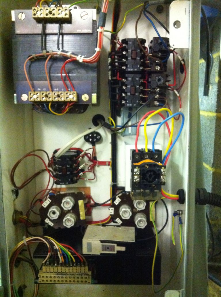
        I have checked the three feeds from the Transwave arriving in the cabinet and I am getting 420v, 420v and 0v across the three pairs (which I think is correct), the six fuses (FU1-3, SFU1-3) all test ok, and if I manually press contactor C3 the motor runs but does not latch.

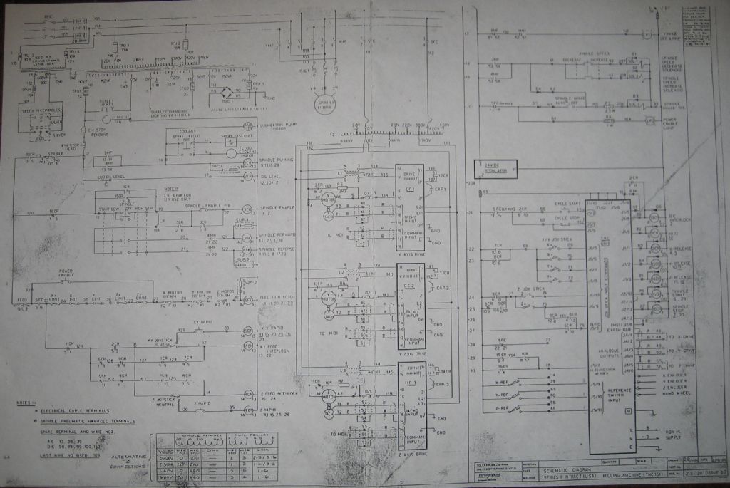
        Q1: could anyone let me have a detailed circuit diagram for the cabinet please? I have the 1979 drawing from the manual but it tells me nothing I can follow. I want to be able to trace from the 'run' button to contactor C3 that I would guess is not firing.

        Q2: anybody have an idea what may have blown/tripped if I did reverse the motor too quickly?

        Q3: A year ago I did have in mind fitting a 90L frame motor on an adapter plate in place of the pancake motor with a Newton Tesla inverter and remote handset; maybe this problem might spur me to do it. My question is how to keep the 6F long feed working if I take all the three phase out of the cabinet. I think the 6F control board only needs 110v, so is it sensible to rewire the input to the big transformer from 420v to 220v and use a new 220/240v fused supply? Will the contactor for the long drive still work so that I can isolate it still from the front panel?

        Norm

        bridgeport cabinet.jpg

        Edited By norm norton on 17/02/2016 14:42:04

        #225822
        Emgee
        Participant
          @emgee

          Hi Norm

          Have you checked if there's an overload tripped ?

          Emgee

          #225823
          Chris Evans 6
          Participant
            @chrisevans6

            My Bridgeport was always unhappy running off a Transwave static converter and kept knocking one of the trips out. Thinking the trip was faulty I changed it but it was no better. The machine now runs well off a VFD but I still have the trip I removed that I could send to you if required. After advice from this board I disconnected the 420 volt input to the transformer and put a 240 volt supply to the transformer with negative to the zero and positive to the 220 and the traverse motor runs.

            #225827
            Clive Foster
            Participant
              @clivefoster55965

              Norm

              As the motor runs up OK when you manually operate the contactor its likely that the problem lies with the overload cut out system. As far as I'm aware Bridgeports of your era are, like my slightly earlier machine, fitted with overload cut outs which can be set for either manual or automatic operation. If set to manual you have to operate a small switch on the input side to reset the device whilst in automatic mode it self resets after a suitable interval. The selector / reset switch usually ends up close to the cabinet side and its pretty much impossible to see whether its set to automatic or manual. Automatic re-setting can become unreliable on older machines. Presumably because it sits there for years and stuff builds up so the spring or whatever that provides the re-set action isn't strong enough to bring things back into position. Mine decided tor randomly trip out and not reset for, presumably, similar reasons. Cure was a good spraying with contact cleaner lubricant accompanied by operating the manual / automatic / reset switch a few times.

              For all practical purposes wiring diagrams for machines with DC motor driven feeds, 6F / 8F, are interchangeable with the transformer, contactor and overload connections clearly shown on the left hand side. All the contactor overloads are in series so if any one has tripped and not returned nothing will work. The feed control part is always bit cramped and not exceptionally clear.

              The feed and contactors all run off 110 V, usually marked LL1 and LL3 on the wiring diagram so if you switch the transformer input to 240 V everything in the electrical cabinet will work as it should.

              Replacing the pancake motor isn't as easy as it seems. The output shaft is much longer than a standard motor so you need to put an accurately concentric extension on. Any error and it will vibrate like nobodies business, as my pal John found out. Mounting is bit tricky too. John butchered the front bell end of his pancake motor to make a mount and fixed the adapter plate to that. Personally I'd fork out for a quality re-build on the pancake motor if it went wrong. Its a high quality machine and almost certainly far better than anything affordable found via the usual sources. The one major weakness for home shop folk is that its not particularly happy on static converters so if its not in pretty good order a static will kill it given enough time. Probably several years in a home shop but fail it eventually will.

              Static converters should really be set by equalising winding current and getting relative phase as close as possible. Not practical for most folk who must resort to getting the phase voltages as close as possible hoping the passing errors are similarly small. Unfortunately even quite small voltage errors, 10 to 20 volts, can be associated with much larger current errors to which some motors are more sensitive than others. I would never run a Bridgeport pancake motor off pure static converter. Putting an pilot, unloaded, motor in series makes them much happier.

              Clive.

              Edited By Clive Foster on 17/02/2016 16:26:16

              Edited By Clive Foster on 17/02/2016 16:27:45

              #225836
              Les Jones 1
              Participant
                @lesjones1

                Hi Norm,
                Have you checked that you have the 110 volt output on the transformer ? I think this is use for the control circuits.

                Here is one schematic I have that may help you to trace the fault.

                lbp_schematic_02.jpg

                Les.

                #225842
                Phil Whitley
                Participant
                  @philwhitley94135

                  In the picture of your cabinet, it appears that the screw in fuse (if that is what it is) on the extreme left of the cabinet is blown, as its indicator is not visible in the window. . The output from the3 phase transwave should be 220v on each phase when tested between phase and ground (earth). Check through the overloads with a multimeter (POWER OFF!) to confirm continuity. It is possible that the missing phase is one of the phases that operates the starter coils in the contactors, so the motor runs up when you manually close the contactor but will not energise when you press the start button. On pure three phase systems, the Coil on the contactors is rated at 440v and operates between two phases, if either of these phases is missing the start button will not work. Is there a button marked "reset" or possibly "STOP" (Reset). if there is push this and try again!

                  #225843
                  Phil Whitley
                  Participant
                    @philwhitley94135

                    OK, swift rethink, can't actually make out the circuit diagram, but if there is a 110v control circuit you will have to test for this voltage to earthy at the start button. If it is not there, that is the problem. Is there a neutral in the cabinet, or is it just 3 phase?

                    Phil

                    #225844
                    Les Jones 1
                    Participant
                      @lesjones1

                      Hi Norm,
                      The file I have of the schematic is slightly better quality than it is in my post on the forum. If you would like it emailing to then PM me with your email address.

                      Les.

                      #225853
                      norm norton
                      Participant
                        @normnorton75434

                        Thanks for all the replies.

                        I feel a bit of a fool because I had not noticed anything that looked like a trip that had released but with all the suggestions about the overloads, when I poked OL3 it clicked and now it all runs. Dooohh…..

                        Phil, the Transwave only gives a voltage on two of the pairs when no or minimal current is drawn, that is how they work. The third phase is generated by inductance (I think) when the motor starts to draw current. Yes that fuse is missing and someone before me bypassed it with the fuse unit that lies in front.

                        Chris you have kindly confirmed my thoughts that I can rewire that transformer to 220v input and I note that yours is working well.

                        Clive your comments are very helpful. I must see if the trips are on auto or manual. Yes I can see that extended running on the Transwave static might compromise the pancake motor. But since the motor is strictly 440v only I guess my only options are a 2kw rotary converter which at £700 is more than a new 220v motor+inverter+ controller at around £500. I have found your helpful comment on 21/07/15 http://www.model-engineer.co.uk/forums/postings.asp?th=109038 about the Direct Drive inverters but my Bridgeport is the only one my machines still needing 440v.

                        Regarding the spindle length J Stevenson did comment in http://www.model-engineer.co.uk/forums/postings.asp?th=107454 that only 42mm of the 50mm 90L spindle is useable to hold the pulley. I have looked at my dimensions and estimate that mine is worse that that. With an 8mm thick adapter plate the pulley would sit on something like 37mm of the 90L spindle. Is that enough for a secure drive? Does the pulley need boring out and a strong sleeve loctiting in and key that to the spindle?

                        Norm

                        Edited By norm norton on 17/02/2016 20:45:23

                        #225855
                        Phil Whitley
                        Participant
                          @philwhitley94135

                          Hi Norm, Not familiar with transwaves, but gathered afterwards that the third phase is generated by the motor itself. then checked in my Brooks book, and it all came flooding back! Yes, it is usually something simple! I am lucky, I have real three phase! Glad you solved it!

                          pHIL

                          #225859
                          John Stevenson 1
                          Participant
                            @johnstevenson1

                            Norm,

                            Looked at the last post you linked to and saw that I never replied to it.

                            To extend the shaft on Bridgy motors I turn the existing shaft down to below the size needed, stub an extra piece in. Weld the whole lot up so it back to basically being one piece and then turn and keyway to the size needed. Sometimes I bore the pulley out to fit a standard sized metric shaft and other times I turn the motor to match the original pulley.

                            Depends what the punter wants. Latter is still standard to a point but the first isn't as you won't be able to buy another long shaft metric motor but usually this mod is only done once.


                            Think I may still have some laser cut conversion plates, need to check.


                            If you want a motor then PM me as I work for 3 of the main importers in the UK and I 'know' I can better any price you see on the net. Often it's possible to get a larger motor much cheaper than a smaller one, it depends on the scale of ordering at the time.

                            Edited By John Stevenson on 17/02/2016 21:29:00

                            #225861
                            norm norton
                            Participant
                              @normnorton75434

                              John

                              Much appreciated, I will PM you as suggested.

                              #225866
                              Clive Foster
                              Participant
                                @clivefoster55965

                                Norm

                                I think my mate John ended up doing pretty much what John Stevenson does to get his extended shaft. First try was to start with a shaft large enough to be bored a tight fit on pretty much the whole of the motor shaft with final fixing by grub screws. Wasn't much run out when the end was turned down to fit the pulley but still too much. Pretty sure that the compound shaft was much longer than ideal too.

                                Simply fitting a pilot motor, 3 HP or so, will make the machine run smother. When I was using a MotorRun static converter on my Bridgeport I put a 5 HP motor, 'cos that was I had, on as pilot which made a very noticeable difference in running and eliminated the need to fiddle with the capacitor switch for different loads. Suspect the Bridgeport really wanted a setting midway between two of the three switch positions.

                                Clive.

                                #225867
                                norm norton
                                Participant
                                  @normnorton75434

                                  Clive

                                  Forgive my ignorance, I could look it up but I will ask, how is a pilot motor wired in? I am guessing it is in parallel and as it has no load, but is spinning, it has the effect of stabilising/damping the Transwave output?

                                  Norm

                                  #225869
                                  Emgee
                                  Participant
                                    @emgee

                                    Hi Norm

                                    I don't have a transwave unit but a similar type and run the pilot motor in parallel, the pilot runs continuosly when there is power output from the inverter, there is no load on the pilot motor.

                                    Emgee

                                    #226007
                                    Clive Foster
                                    Participant
                                      @clivefoster55965

                                      Hi Norm

                                      As Emgee says simply connect the pilot to the static converter output in parallel to the machine and run the converter up before switching on the machine. Effectively converts a static converter to a rotary converter. As I understand things the pilot motor acts as a rotary transfromer giving close to proper three phase to the working motors avoiding the self generation requirement so things are much more stable. Allegedly there is also some conversion of mechanical rotational inertial energy from the pilot motor rotor into electrical energy which helps bit under load changes.

                                      Ideally the pilot motor needs to be bigger than the load motor. It can also be a bit over the rated static converter output. My MotorRun static converter was 4 HP but a 5 HP pilot motor worked just fine.

                                      Clive.


                                      Edited By Clive Foster on 18/02/2016 22:34:00

                                      #226027
                                      Johnboy25
                                      Participant
                                        @johnboy25

                                        Without reading through the whole thread – from the photo, it looks like the bottle fuse bottom left middle has blown… This type of fuse has an indicator that changes when it's done its job.

                                        I'll carry on reading the rest of the thread now. 🤔

                                        John

                                        P.S. I had the same control box on my Bridgeport now fed via an inverter for the motor drive.

                                        P.P.S. there is a circuit diagram on the Bridgeport user group on the yahoo site, I put it there for someone who needed it for this type of Bridgeport control cabinet. WADR – Les,  I'm  pretty sure this isn't the circuit diagram for this machine.

                                        Edited By Johnboy25 on 19/02/2016 09:36:02

                                        #226032
                                        Johnboy25
                                        Participant
                                          @johnboy25

                                          It's here two version of the U.K. Bridgport circuit schematic. Enjoy!

                                          https://groups.yahoo.com/neo/groups/bridgeport_mill/files/Johns%20stuff/

                                          John

                                          #226051
                                          norm norton
                                          Participant
                                            @normnorton75434

                                            John

                                            Many thanks. I was going to ask if anyone had further circuit diagrams. The WD-153 is for my machine and it is the diagram that is in the available manuals. But, it is basically a circuit logic diagram that sort of helps, but I could really do with something with cable colours and cable number codes.

                                            I am going to fit a new motor with VFD so I want to tidy the cabinet. Remove all the 3 phase, bring in some organised 240v and use the Bridgeport front switch box as additional stop/go for the VFD, and keep the traverse isolator switch.

                                            The problem is that the front switch box harness comes into the cabinet as a bunch of coloured wires, many of them red, merges into the system harness and wires pop out at various places on contactors, etc. I am going to have to take the whole harness apart and draw up my own diagram, then reverse engineer the front switch box to deduce which wires come from which switch. Really it is no more complex than rewiring an old motorcycle so I shouldn't fuss.

                                            During a quick look at it yesterday it seemed that the 6F long feed board used 110v AC single phase power only. I could not immediately see where the 50v pink tapping from the transformer was used?

                                            All doable, but is there any other type of diagram that you are aware of John?

                                            Norm.

                                            #226053
                                            John Stevenson 1
                                            Participant
                                              @johnstevenson1

                                              Pink tapping could be 48v machine light ?

                                              Seen 12v, 24v and 48v lighting on machines.

                                              #226065
                                              Johnboy25
                                              Participant
                                                @johnboy25

                                                Hi Norm.. Not sure what the 48/50v AC is used for but I'll take a look… I'm sure you've worked out the horizontal feed motor is powered from 110V (or 115V if for our American colleges) the motors rated at 370W if my memory correct. I was going to change the transformer just accommodate the feed motor plus a bit for the 110V control circuit.

                                                If you're going the inverter route then a lot of the control harness will become obsolete – if your use to motor cycle wiring there nothing as complicated than that. Just the fast feed and motor feed speed needs a thought.

                                                This style of control cabinet is too shallow to accommodate the inverter so it's planned to section the cabinet and weilding in a 50 mm or so to give me the depth. I was going to replace the entire control cabinet but the quality and the gauge of metal used is far superior than othe electrical enclosure I'm use to.

                                                hope this helps… I'm in Reading if you need any other assistance.

                                                John

                                                #226066
                                                Les Jones 1
                                                Participant
                                                  @lesjones1

                                                  I think that you will find that the 50 volts is for a low voltage light on the machine. 50 volt lights used to be common on machines.

                                                  Les.

                                                  #226077
                                                  Clive Foster
                                                  Participant
                                                    @clivefoster55965

                                                    Norm

                                                    No official detailed colour coded wiring diagrams were ever produced. Mine has numbered and lettered sleeves on most wires which is sufficent help although some have fallen off and / or got lost during previous servicing.

                                                    Putting the inverter in the cabinet may protect it but also makes it impossible to read frequency display on the box so you need a remote readout if you want to know what speed you have set.

                                                    Messing around altering wiring is a bad idea and more work than it sounds. Half new / half old non standard set-up is asking for headaches if it goes wrong. Probably the major issue that pushed me to the whole shop plug'n play system. Easiest way is to switch the transformer input to 220 /240 volts for the long feed system and run the spindle motor direct off the VFD. Or just junk the whole cabinet and give the feed unit its own small box and transformer. A compact VFD unit can be made to sit very nicely on the left hand side of the head. Fitted one in that manner for friend John on his J head equipped round ram Bridgeport, unfortunately no pictures. Separate motor supply looses the spindle-feed-pump interlocking but the Americans generally never had this and go along OK. Alternatively you could probably use the contractors as pure switches to control the VFD via its remote input ports after slipping the power wiring out of the way and running suitable signal rated cables.

                                                    Clive.

                                                    #226082
                                                    norm norton
                                                    Participant
                                                      @normnorton75434

                                                      Thanks guys. Yes, I took the bulb out and it is 50v, so that answers that one!

                                                      Clive, thanks for confirming there are no other diagrams. I also have some numbered sleeves on cables but they seem only to have been numbered one end (?!) – it was probably done for assembly confirmation I suppose.

                                                      I think that the VFD must be outside the cabinet because the fans pull quite a bit of air through them, and up highish away from swarf! I will use the VFD extension/dongle to control the motor but I want to use the Bridgeport front switch box to power up the system, enable me to switch on/off the long drive feed, and I have an emergency stop by my knee to switch off everything. I'll sort it out, it will be fun to wire nicely.

                                                      Does anyone know what gives if the long drive motor comes up against a firm stop, or the table lock is on (which has happened once or twice)? I'm assuming there is a slip clutch in the drive motor somewhere, or does it just stall?

                                                      Norm

                                                    Viewing 25 posts - 1 through 25 (of 27 total)
                                                    • Please log in to reply to this topic. Registering is free and easy using the links on the menu at the top of this page.

                                                    Advert

                                                    Latest Replies

                                                    Home Forums Manual machine tools Topics

                                                    Viewing 25 topics - 1 through 25 (of 25 total)
                                                    Viewing 25 topics - 1 through 25 (of 25 total)

                                                    View full reply list.

                                                    Advert

                                                    Newsletter Sign-up