Wiring in a New Coolant Pump.

Advert

Wiring in a New Coolant Pump.

Home Forums General Questions Wiring in a New Coolant Pump.

Viewing 12 posts - 1 through 12 (of 12 total)
  • Author
    Posts
  • #196283
    Bob Rodgerson
    Participant
      @bobrodgerson97362

      I purchased a new coolant pump foor my manual milling machine because the old one went mental and blew up a few weeks back.

      Today I got the new pump which is obviously a generic Chineese/Tiwaneese make because it fits directly onto the tank I have, using the same hole spacing and it is physically the same size and shape as the old one. I thought that it would have a nice simple terminal block with obvious positions for live Neutral and Earth wires however it doesn't.

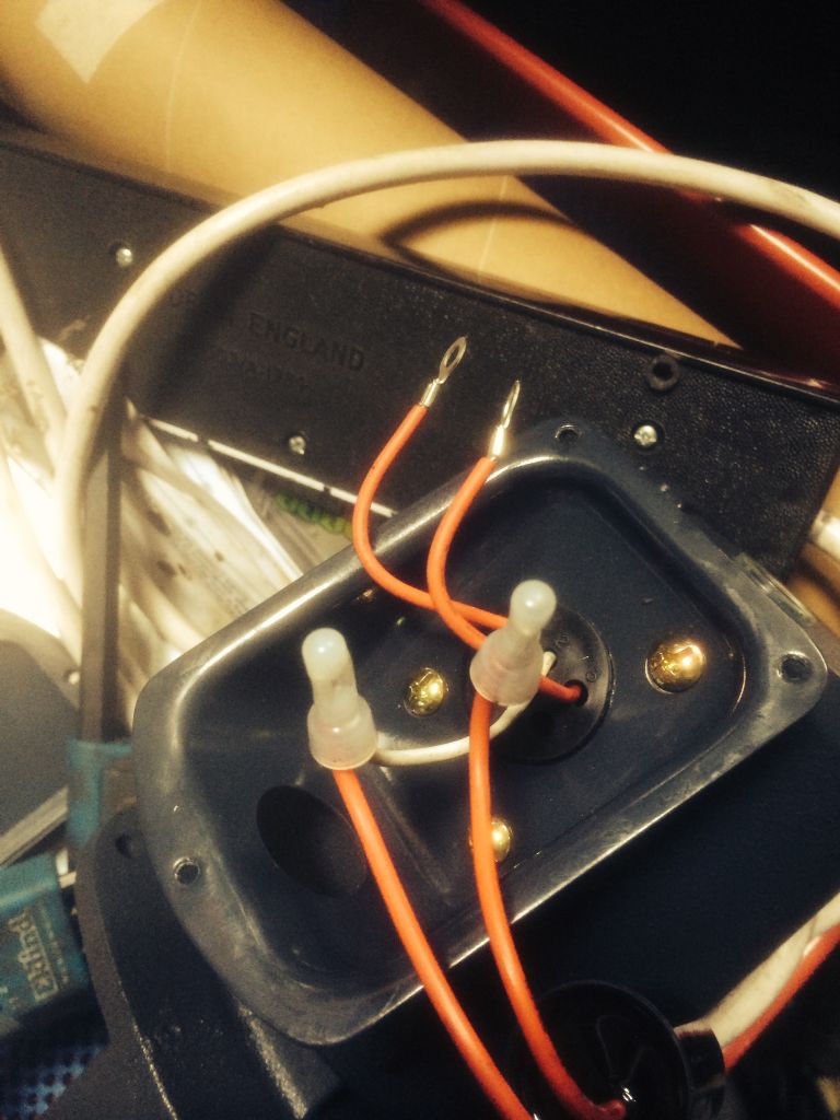
      Here is a picture of the wiring facing me when I took the terminal cover off.

      pump.jpg

      There are six holes numbered 1-6 in the back of the terminal box. No.s 1 & 3 are both red wires that have a crimped terminal on their ends. N's 2 & 5 wires are both white and are crimped to the two wires that come from the Capacitor.

      I presume that it doesn't matter which of the two red wires with the crimped terminals are connected to, either live or neutral and also I presume that the earth wire is terminated under one of the screw heads that holds the terminal box to the pump motor body.

      I am of the firm belief that wire is used as a conduit for smoke and other than that have no idea how it all works but would appreciate some help prior to blowing myself up.

      Advert
      #23973
      Bob Rodgerson
      Participant
        @bobrodgerson97362

        Replacing a coolant pump.

        #196339
        Stuart Bridger
        Participant
          @stuartbridger82290

          My first suggestion would be to contact the vendor for wiring instructions. You presumption is most likely correct though, but if any doubt I would recommend contacting a qualified electrician to check it over. Given that there are six wires, I suspect that it is a 3 phase induction motor, with a motor run capacitor for the 3rd phase, but no guarantees.

          .

          #196343
          Bob Rodgerson
          Participant
            @bobrodgerson97362

            Hi Stuart,

            I'm sure your assumption is correct. As I see it swapping the two red wires around will only change direction of rotation and on this type of pump with straight impeller blades makes no difference to the pump output.

            #196346
            Les Jones 1
            Participant
              @lesjones1

              Hi Bob,
              From your picture it looks like the two white and the two wires from the capacitor are all connected together. Is this the case. I would have expected one white wire from inside the motor to go to one side of the capacitor and the other white wire to go to the other side of the capacitor. I don't think it is a three phase motor as there are only four wires from inside the motor. A slightly wider angle shot would help as it does not look like the terminal box is on the side of a motor. Also what are the thick white wires around the outside of the terminal box ?

              Les.

              #196352
              Bob Rodgerson
              Participant
                @bobrodgerson97362

                Hi Les here is another picture and as you can see both the white wires are connected to the capacitor.

                pump-2.jpg

                It is not too clear which wires go where even from this picture, it looks like two red wires are joined at the crimp connection to the right but this is not the case there are definitely a white from the motor and red wire from the capacitor joined together at these connections.

                Bob

                #196354
                Bob Rodgerson
                Participant
                  @bobrodgerson97362

                  Les,

                  I forgot to add, the thick white wire on the photo's is some 3 core power cable from the original pump.

                  #196359
                  John Rudd
                  Participant
                    @johnrudd16576

                    To avoid any confusion here,

                    There are two RED wires with ring lugs attached……yes?

                    There are two WHITE wires each crimped/joined to the two RED wire coming from the capacitor yes?


                    There are no more wires coming from the pump unit yes ?

                    A standard configuration for a permanent  cap motor…..


                    In that case the mains L/N goes to the two RED wires with the ring lugs and Earth- green yellow to the metal casing……


                    Could I ask where you got the pump from ? I'm thinking of adding a coolant system to my new lathe….


                    Edited 

                    Edited 

                    Edited By John Rudd on 10/07/2015 11:09:23

                    Edited By John Rudd on 10/07/2015 11:10:26

                    #196379
                    Bob Rodgerson
                    Participant
                      @bobrodgerson97362

                      John,

                      Correct. If that is the case then all is as I thought. I got the pump from RDG after the motor on my portable coolant system that I use on the manual mill blew the capacitor. It is identical to the new unit. It blew the capacitor and I couldn't decifer what capacitance and type of capacitor was required. The wiring was fried too so I'm not too sure if it would still work if a new capacitor were fitted. I suppose the new pump capacitor will have details so that I can determine what is required. If you want the broken pump I can send it to you along with those details for the cost of postage. If it works it's a bonus if not its just a few quids worth of speculation.

                      Regards,

                      Bob.

                      P.S. let me know if you are interested.

                      #196387
                      John Rudd
                      Participant
                        @johnrudd16576

                        Bob,

                        You have a private message ……

                        cheers

                        John

                        #196389
                        Les Jones 1
                        Participant
                          @lesjones1

                          Hi Bob,
                          I agree with John that the two red wires with the eyelets will be live and neutral. It does not matter which is live and neutral.

                          Les.

                          #196395
                          Bob Rodgerson
                          Participant
                            @bobrodgerson97362

                            Thanks les.

                            John. I have responded to your message. I will wire in the pump tonight and let you all know how it goes.

                          Viewing 12 posts - 1 through 12 (of 12 total)
                          • Please log in to reply to this topic. Registering is free and easy using the links on the menu at the top of this page.

                          Advert

                          Latest Replies

                          Home Forums General Questions Topics

                          Viewing 25 topics - 1 through 25 (of 25 total)
                          Viewing 25 topics - 1 through 25 (of 25 total)

                          View full reply list.

                          Advert

                          Newsletter Sign-up