Posted by SillyOldDuffer on 16/06/2018 09:28:55:
When you open up an equipment and find someone else has been 'at it', bear in mind they might have been an electrical genius or a complete incompetent.
The latter I suspect – it looks like the previous owner had just disconnected the motor input from the switch and put a plug on the short length of cord without even trimming the wires to fit. So the clampy thing that's meant to grip the outer sheath was doing nothing. That sort of thing makes me nervous!
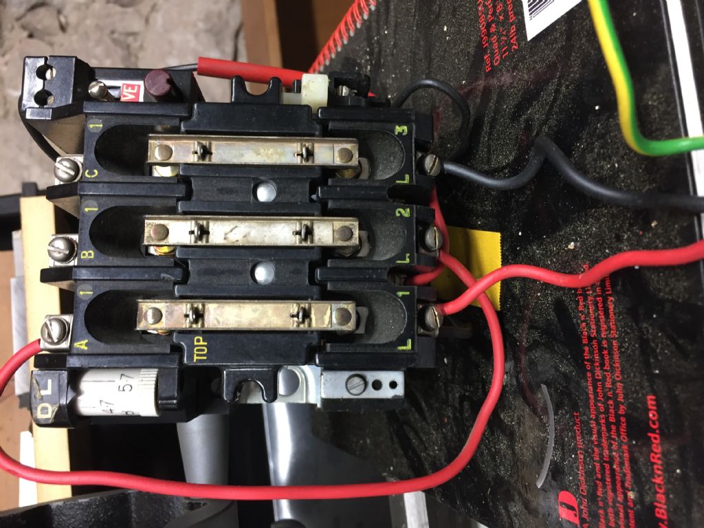
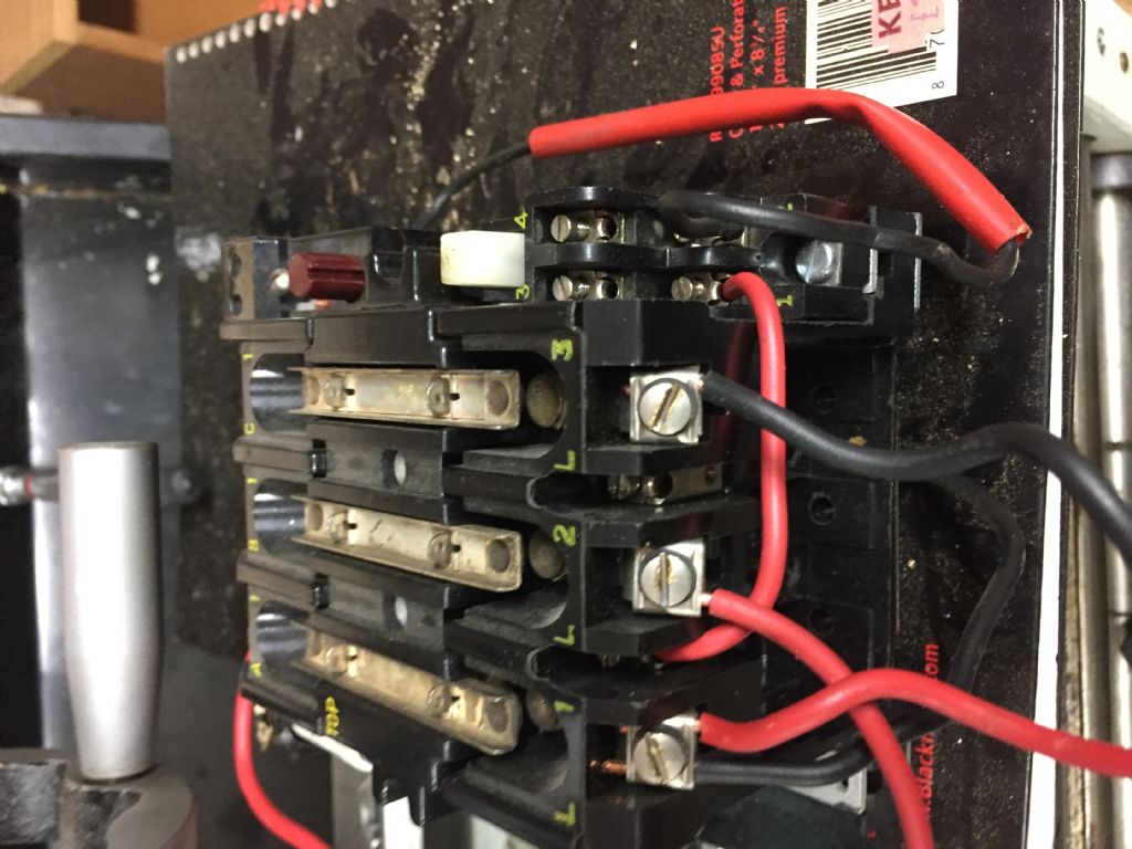
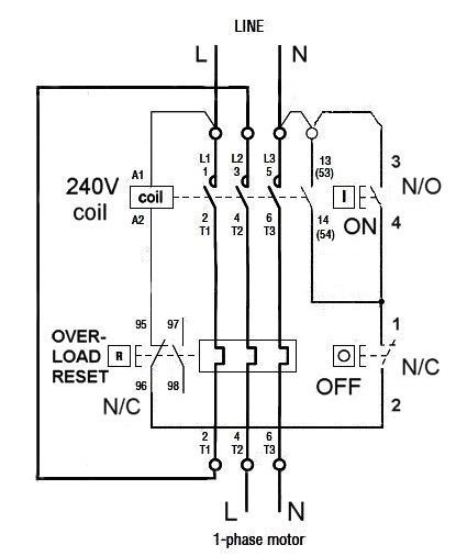
I did what checks I could with a multimeter and all seemed to be in order so I wired it up with reference to John's schematic (it's single phase). Many thanks John, that was very helpful.
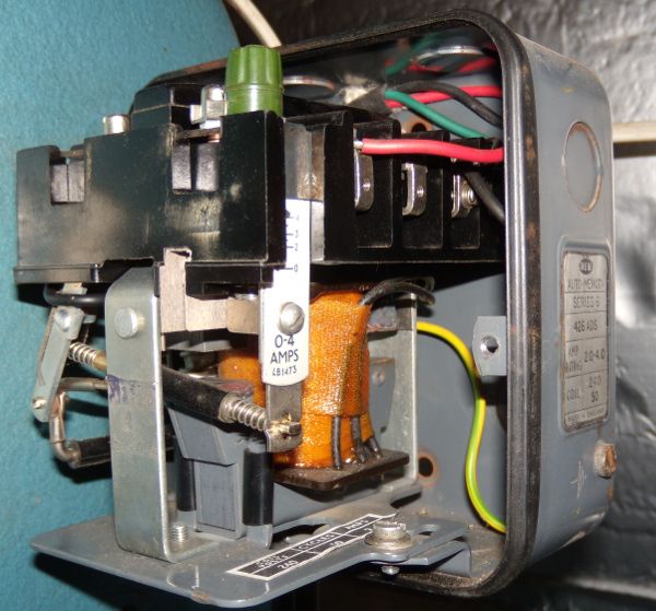
Emgee, you are spot on in your identificaction of the unit – it has the pressed metal case inside which there is sticker giving part numbers for replacement contacts etc. A relic of the days when things were designed to be maintainable perhaps. The red button is indeed the stop switch rather than an adjustment, it is actuated by the Big Red Button on the front casing of the unit, as you know.
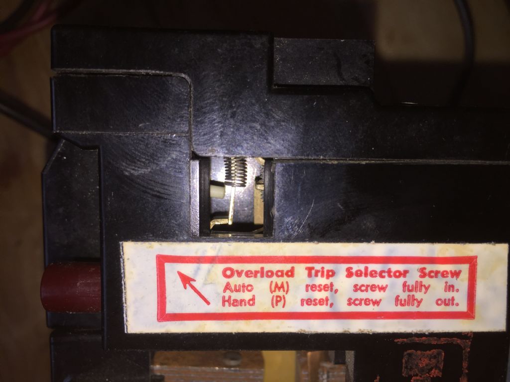
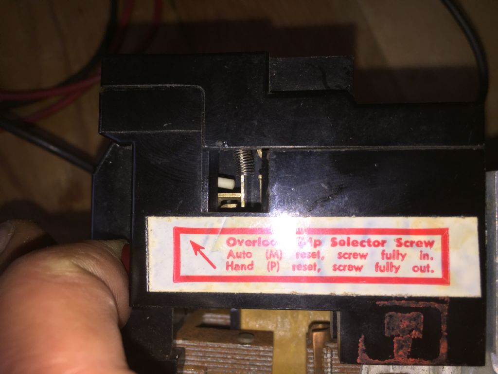
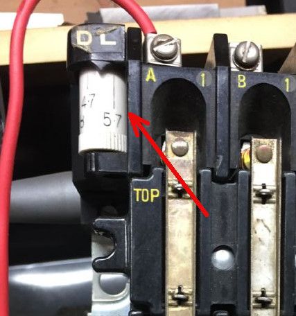
I'm still in the dark about the white wheel Dave pointed to. It's calibrated in Amps, and is marked max current or somesuch. I just left where I found it at somewhere around 5A. Could it be somehow connected to the overload trip mechanism? The motor is 3/4 HP 4.5A according to the plate btw.
Anyhow, all is working fine now, and I'll never know why the NVR was taken out of circuit – maybe the previous owner just couldn't figure out how to wire it.
I did have a shaky moment when I first fired it up and it appeared not to stop when I hit the red button – turned out the motor takes about 35 seconds to wind down, so the bearings are in good shape I guess!
Thanks again for the help, Robin.
Edited By Robin Graham on 16/06/2018 23:56:30
Robin Graham.


