What Did You Do Today 2020

Advert

What Did You Do Today 2020

Home Forums The Tea Room What Did You Do Today 2020

Viewing 25 posts - 301 through 325 (of 636 total)
  • Author
    Posts
  • #474673
    jimmy b
    Participant
      @jimmyb

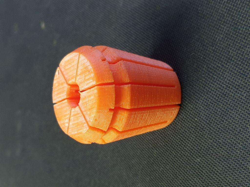
      This mornings efforts!

      20200525_044147.jpg

      Actually works quite well.

      Jim

      Advert
      #474806
      John Hinkley
      Participant
        @johnhinkley26699

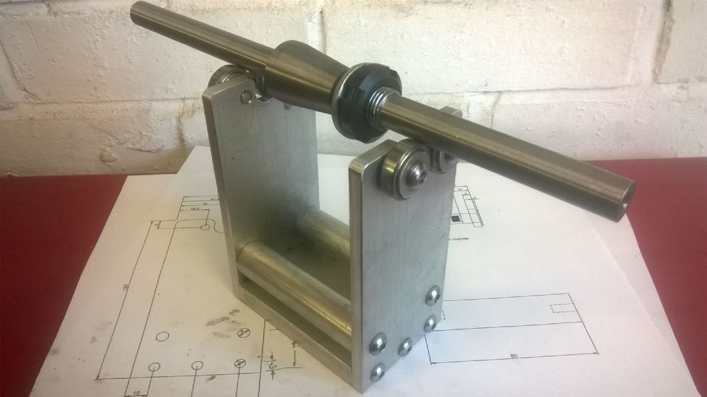
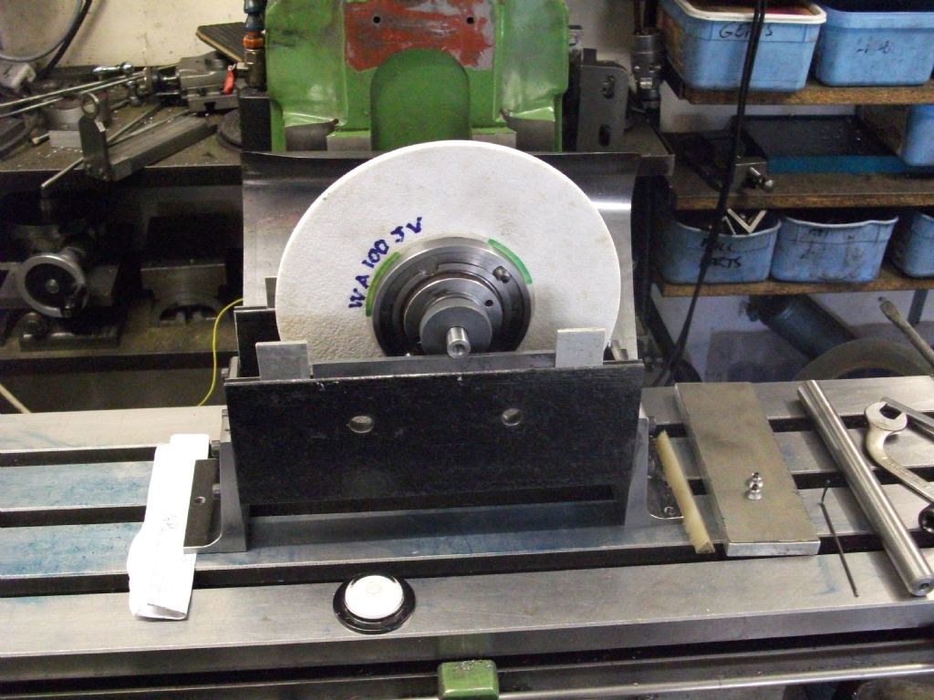
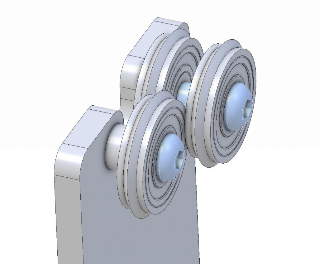
        Been doing a bit of surface grinding of late and although I'm fairly pleased with the results, I thought it could be better. I did some research, being a newcomer to grinding, to see how I could improve the "rippled" finish. It appears that the most likely cause is an unbalanced wheel, so, having slightly damaged the wheel supplied with the machine, I obtained a new Norton Abrasives one through RS Components. I tried balancing in my usual manner, that is, putting two 1-2-3 blocks on end on the mill vice and laying the balancing mandrel on the top. Inevitably, it tried to roll off! Long story short, I set to at the computer screen and drew up the balancing jig below in Atom 3D, using measurements that would enable me to build it with material I had in my scrap boxes. The vertical side pieces were machined and drilled while clamped together to help retain alignment and the ball bearings were ones bought as a job lot on eBay.

        Balancing fixture

        Finished it this morning and going to try it out this afternoon, after re-dressing the periphery. Luckily the wheel hubs are ones with three balance weights incorporated in the rear face.

        John

        #474820
        John Hinkley
        Participant
          @johnhinkley26699

          Well, that was a bit of a failure and a bit of a success!

          Failure – the balancing jig didn't work as I expected. Either there's too much drag in the bearings and/or too much contact area between the bar and the bearing outer surface, or the wheels is perfectly balanced! It didn't move, no matter where the wheel was placed. I even taped a 10mm nut to the periphery of the wheel and it still wouldn't swing!. Back to the drawing board.

          I did, however make some improvements to the finish by altering my technique by dressing the wheel quite aggressively (I thought) and then taking the X-axis movement more slowly than before, making sure that each pass "sparked out".

          I'd really appreciate any further suggestions from those more experienced in surface grinding as to how I can further improve the finish.

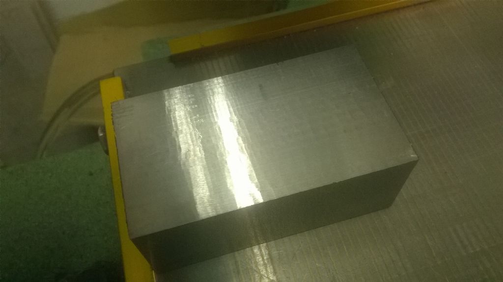
          Here's what it looked like before my improved? technique:

          rippled finish.jpg

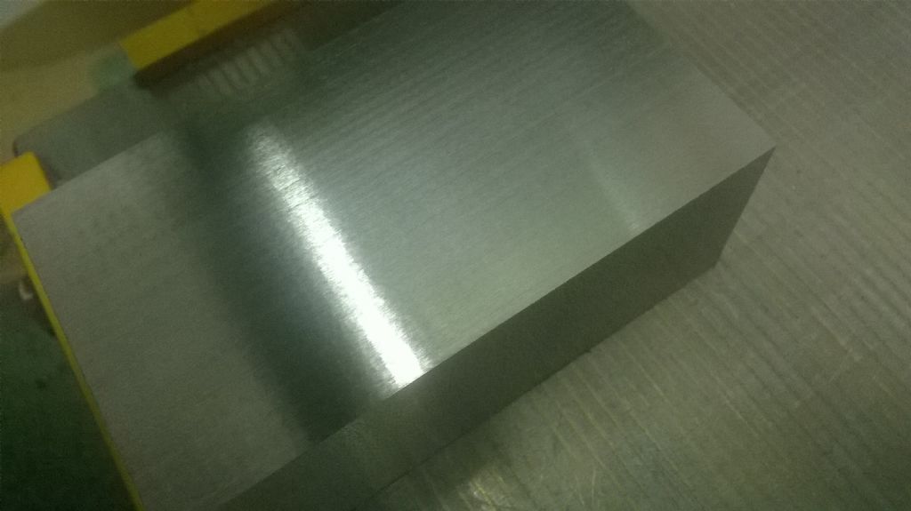
          The photo quality is not the best as I only have an old smartphone, no dedicated camera, but I think the improvement, though slight, is distinguishable:

          improved finished.jpg

          Perhaps, on reflection, this ought to go in a separate thread, rather than clutter this one?

          Mods feel free to do that.

          John

          #474839
          John MC
          Participant
            @johnmc39344

            John, try making some knife edged "tyres" that are pressed on to the bearings, that should reduce the friction. Also get any lubricant out of the bearings then put a tiny bit of WD40 (or similar) to lube the bearings.

            John

            #474845
            HOWARDT
            Participant
              @howardt

              John, as John MC said, make the rollers for the bar knife edge and larger in diameter with almost dry bearings. Balancers I have seen have rollers at least 75mm in diameter and rotate easily.

              #474851
              John P
              Participant
                @johnp77052

                Here is what i made to do the same job ,this balancing frame made from
                pieces of old steel channel bolted together some slots milled in each side
                for some hardened pieces of gauge plate.Fitted on the machine and
                ground flat some pieces of aluminium at each end to stop the wheel rolling
                off ,three jacking screws to level the frame .The edges should be ground to
                knife edge but the balancing shaft is soft so i left them square.
                Simple and little to go wrong just have to keep the edges clean.

                John

                wheel balancing.jpg

                #474853
                John Hinkley
                Participant
                  @johnhinkley26699

                  John MC and Howardt

                  Thanks for the input, gents. I'd pretty much come to the same conclusion about the bearings. I'll try to make up some knife-edge tyres and see how that goes, but I fear I'll be severely restricted on diameter if I use the same bearings. It's not like I haven't got enough time, though, is it? I'll have a play with the CAD model to get some idea of how big I can go. Another thought has just occurred to me – I could doubleup the bearings with a spacer and run the other between to gain more space. Like this:

                  new version.jpg

                  I'll let you know how I get on. (But not today.)

                  Thanks, again.

                  John

                  Edit:

                  John Pace:  Just seen your posting while I was away 3D-CADding.  That's the sort of thing I should have made, but didn't have the material required.  Something to bear in mind, though.  Thanks.

                  Edited By John Hinkley on 25/05/2020 17:35:35

                  #475094
                  Anonymous

                    I've got some knife edge parallels that I used to balance my grinding wheels. The cylindrical grinder works fine, whereas on the surface grinder I always get a poor finish, mostly rippled as illustrated by John. Manual versus power feed and different step overs seem to make little difference. The wheel gets glazed quite quickly despite being a 46 grit. Either I need to use coolant to prevent the glazing or the wheel spindle bearings are fudged. I'm inclined to the latter. My surface grinder is from the 1940s and the bearings are plain taper. The manufacturer recommends a spindle oil made from white water paraffin. An oil supplier translated that as an ISO3 oil. It's just like water and runs out as quick as I can pour it in. Thicker hydraulic oils also run straight out. It could be that any internal springing pushing the bearings slightly outwards are broken or that the bearings are worn. It's on the roundtuit list to strip the spindle and see what's going on. I should have plenty of time to do that this summer since it doesn't look like I'm going to be working again, at least in the near future.

                    Andrew

                    #475212
                    Anonymous

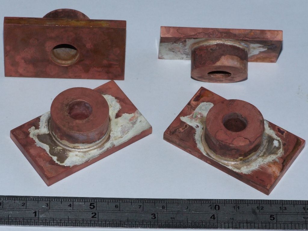
                      Woohoo! Did some silver soldering this afternoon, and it went waaaaaay better than it has done in the past:

                      silver_soldering.jpg

                      They're a bit untidy but I hope to improve on that. I centre popped the bronze plate before assembly so that there would be a gap. In retrospect the gap was larger than it needed to be, which was wasteful of solder. Eventually these parts will become the piston rod glands on my traction engines. Before anyone points it out the boss is not centred on the plate. The final elliptical outline has one side cut off to clear the slidebars.

                      Andrew

                      #475432
                      Anonymous

                        This morning I flew the tug albeit by itself – no glider on the back. It's been nearly six months since I've flown power and if it goes over six months I'm supposed to fly with an instructor. Which would be difficult while maintaining social distancing. To start with I thought I'd spend a few minutes just flying around before attempting a landing. I went to have a look at my bungalow. Then I noticed a red light on the panel, oeeeeer. Darn alternator isn't working. I start the engine with the alternator offline, and having forgotten to connect it and flattened the battery in the past I'm paranoid about putting it online. Looked at the breaker and it's in, trip it and reset, still got a red light. Work through all the other breakers and find a new one on the other side of the panel labelled 'charge'. Press it and whoopee the red light goes out and the ammeter indicates the battery is charging. But the darn breaker won't stay in, took five goes before I got it to stay in. Fortunately it stayed in while I did four circuits and landings. Report the new breaker issue to the Chief Tug Pilot and he says he'll investigate, and find out when and why it was fitted. I'm now happy to start towing again.

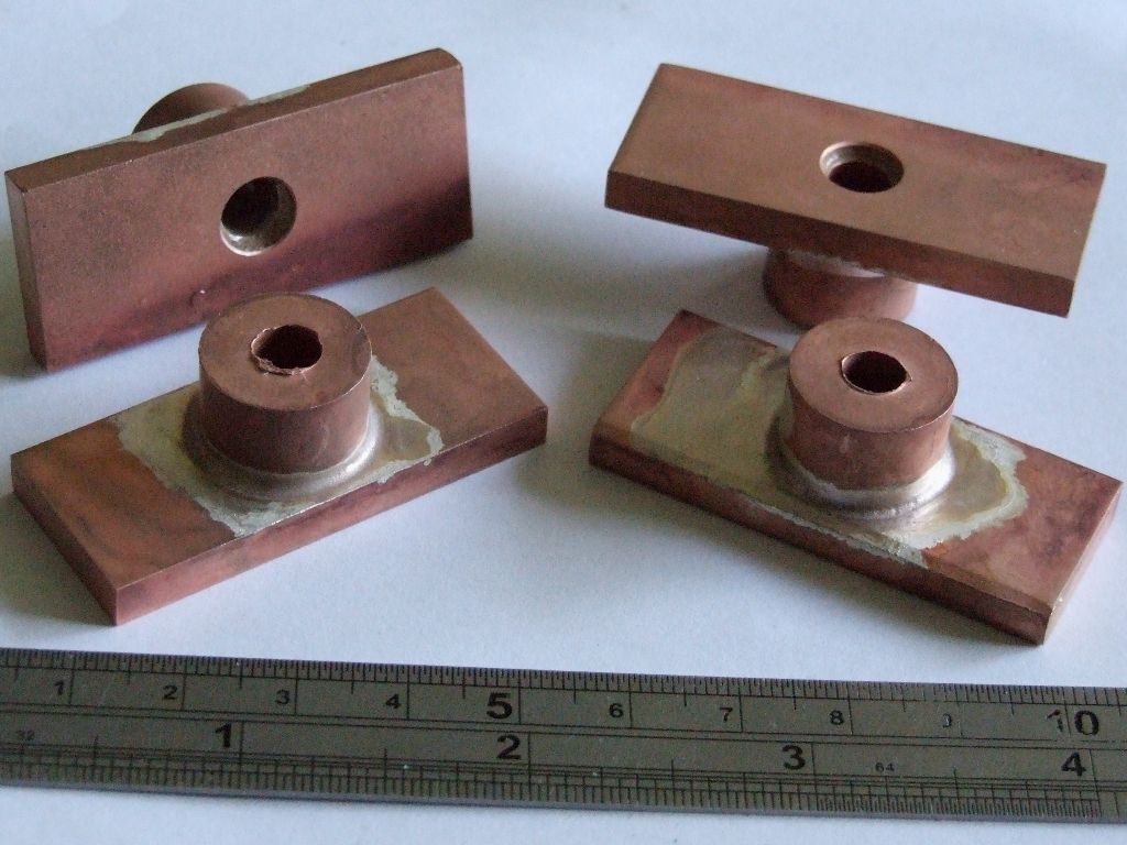
                        This afternoon I did some more silver soldering, on the valve rod glands:

                        silver_soldering_2.jpg

                        This evening I started machining the previous silver soldered parts. The sequence will be:

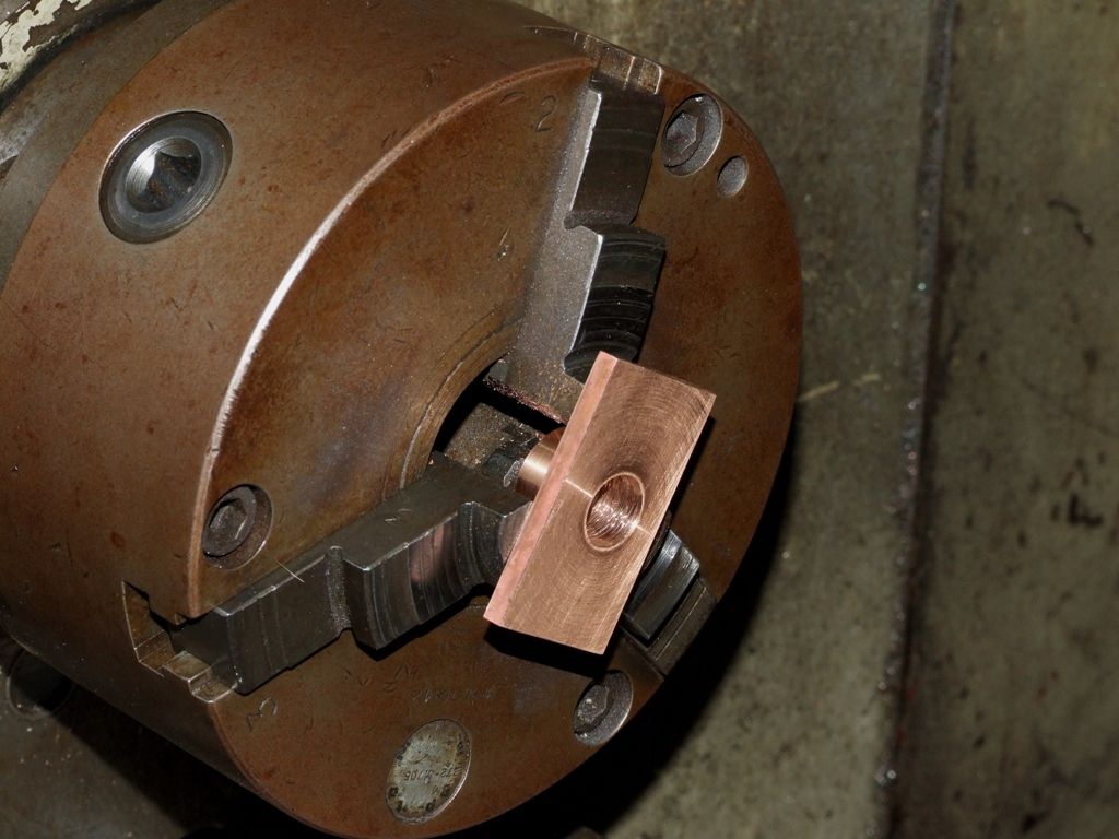
                        In the 3-jaw chuck face one side of the flange and bore/ream the hole.

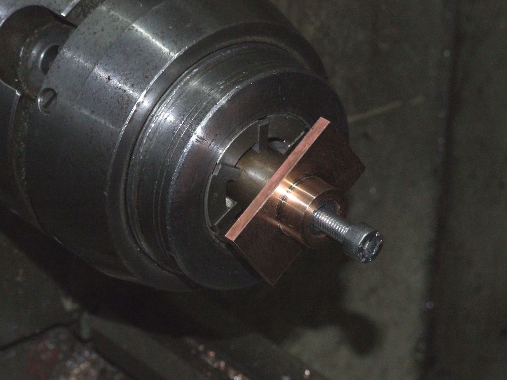
                        Use a split mandrel to machine the other side of the flange, bring the boss to thickness and to the correct diameter, using a micrometer. smile

                        On the mill centre on the hole and offset to drill the holes for the studs.

                        Finally mill the outside profile.

                        Andrew

                        #475443
                        DiogenesII
                        Participant
                          @diogenesii

                          ..sounds like Glandular Fever to me..

                          #475628
                          Mick B1
                          Participant
                            @mickb1

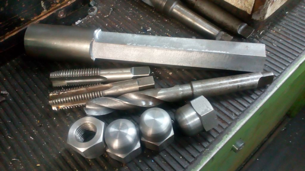
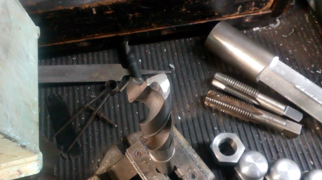
                            Some 1 inch x 8 TPI Whitworth dome nuts for the railway's S160s (US-made WW2 locomotives). I had to chop 2" steel round bar down to 37mm hexagon on the Bridgeport clone. I cheated a bit on tapping size with a 7/8" drill, which is 15 or 16 thou larger than nominal Zeus tapping size, but that'll make hardly any measurable difference to thread strength.

                            Tapping manually was still hard work. The taper tap was already reasonably sharp, but I had to visit the bench grinder with the plug. The drill was already sharp too – I don't know whether it was me that ground it, but it uses the same grind I was taught in the Government Training Centre in the 70s, with a thinned web and point. Started with a BS No.4 centre drill, I could go straight in with the 7/8" drill on the Colchester Student, and the hole measured .876", which is pretty good from the solid without a pilot hole. Fashions change, but I doubt a 4-facet or any of the new-fangled profiles would've made a significantly better job.

                            The dome form comes from a 9,5 rad (3/8" ) carbide router cutter with its shank clamped in a mild steel block in the toolpost. Neither I nor the railway have any bigger rads that I could find, and the loco fitter was quite happy with that. I do that bit, plus some prettying up, at home on the Warco. I've got 2 to finish at home, and will do the remaining 2 tomorrow or when I feel like it – 8 in total, for the fireboxes or something – the railway don't think they'll be running public trains till July.

                            domenutss160.2020-05-28 11.02.32.jpg

                            domenutss160.2020-05-28 11.05.23.jpg

                            Edited By Mick B1 on 28/05/2020 14:31:57

                            #475642
                            mechman48
                            Participant
                              @mechman48

                              Went around the bungalow hosing down & washing all the windows, doors, guttering, down comers, garage door, car. I think that put SWMBO in a lighter mood dont know

                              George.

                              #475722
                              AdrianR
                              Participant
                                @adrianr18614

                                At last, finally finished cleaning my new mill, very happy I did due to the amount of muck I got out of the bits that shouldn't have muck in. It is now all clean, greased, DRO fitted and bolted down.

                                Now I need to tidy up the workshop and perhaps I should also clean the windows etc like George, there was a definite hint the other day.

                                Adrian

                                #476083
                                Anonymous

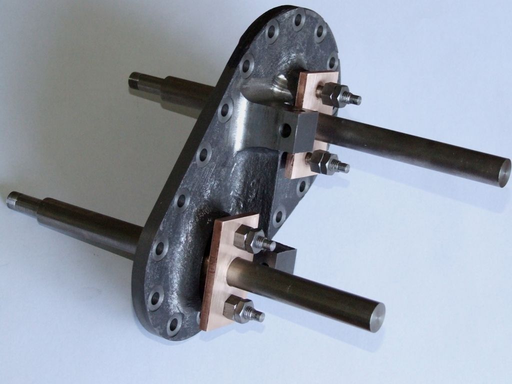
                                  I'm making progress on the piston rod glands, just the CNC profiling left to do. Given the recent post about inconsistent micrometer readings, and the dismissal of micrometers and comments on fitting, I thought I'd expand on how I machined the glands. First, the front face was cleaned up and the hole bored and reamed:

                                  gland_front.jpg

                                  gland_back.jpg

                                  Next, using a split bush, the boss was brought to the correct diameter and length and the back of the flange cleaned up. The width of the flange is not critical, so I didn't measure it but just took enough off to clean up the surface. The nominal width of the flange is 3/16" and the flange was made from 5mm plate so there's some meat to play with anyway. The length of the boss is also not critical so it was measured with a rule.

                                  For the diameter of the boss I first measured the recess in the cylinder cover. The recesses were 'bored' out with a 7/8" endmill but have come out a bit oversize, measured as 0.892". I turned the boss to 0.891" using a micrometer and the lathe cross slide dial, with the number noted. A sanity check with the cylinder cover confirmed that the boss fitted with slight play, as I wanted. The bosses on the remaining three glands were turned to the same diameter using the same cross slide dial number, and sanity checked with the micrometer. All four bosses are within a thou of each other with no great effort on my part, other than remembering a number.

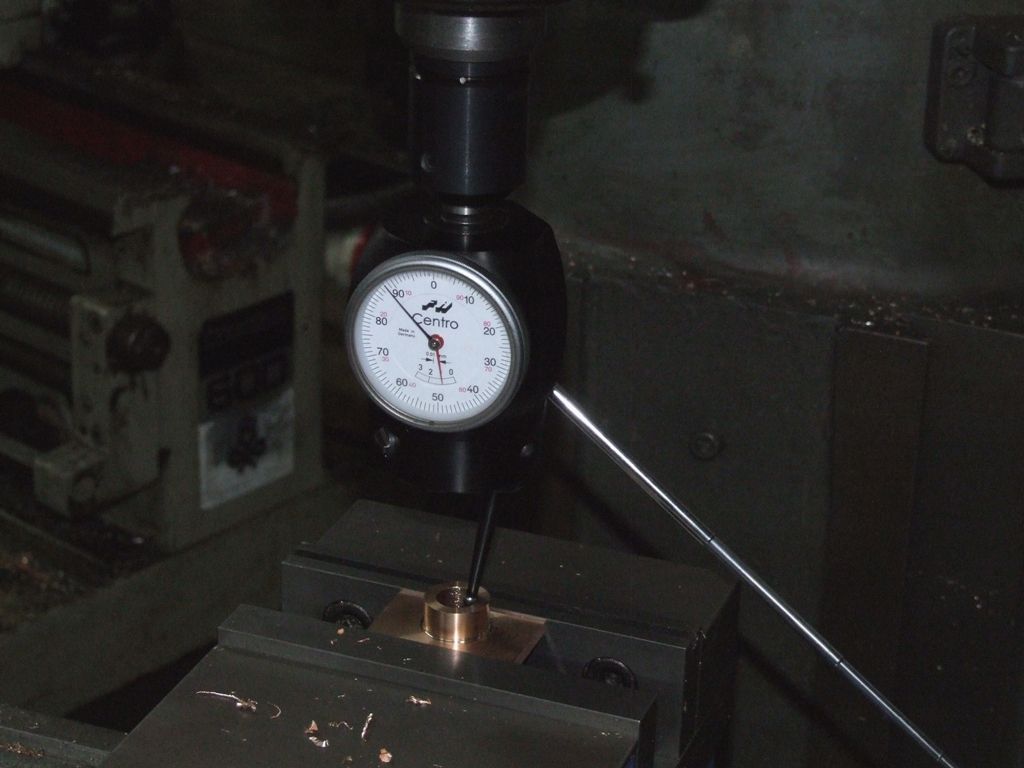
                                  Finally the centre of each hole in the boss was picked up on the vertical mill and holes for the studs drilled using the DRO to position them relative to the central hole:

                                  gland_centro.jpg

                                  The holes for the 1/4" studs were drilled 6.5mm. So in theory there should be 3 thou radial clearance, although bronze has a nasty habit of closing up slightly on drilled/reamed holes. Here's the cylinder cover and glands assembled:

                                  glands_assembled.jpg

                                  All glands fit in each location with the piston rod running smoothly in all cases. So basically the glands are interchangeable and I don't need to mark each one for a specific location.

                                  It took longer to write about than do. My point is that with some thought and proper measurements it is possible to make parts that fit without each part being specific to one location or needing post-machining fitting. Which is good for a lazy bones like me.

                                  Andrew

                                  #476106
                                  Paul Kemp
                                  Participant
                                    @paulkemp46892

                                    Andrew,

                                    Good method, just as an example though to save machining a fixture / bush and with my blanks being castings I held them on the flange in the 4 jaw, machined the back face of the flange and the boss and drilled / reamed the holes to have everything concentric at one setting and then held the machined boss in the three jaw to skim the front, just another different way of doing it for the same result.

                                    The important bit of your post though was the measuring and the decision process. I can just imagine some on here when considering previous discussions on measurement and micron accuracy will have palpitations reading you didn't measure the flange thickness and machined the boss length to a rule! The fundamental thing to take from your post is the step where you consider which dimensions are important and require reasonably close tolerance and those that are really unimportant in the great scheme of things. Also the choice of machining operations and work holding to make sure the parts that need to be concentric are.

                                    It amuses me greatly reading some posts where the underlying importance of having a tolerance and what that tolerance should reasonably be is lost under a fixation of making something exactly to a size shown on a "drawing". If you took most model drawings to a machine shop to have a part made they would likely show you the door or at least have a detailed discussion on what the intended outcome is and agree some tolerances to be applied. Take for example a weighshaft bush and weighshaft, on a 'normal' set of commercial drawings the shaft and the hole in the bush will be dimensioned as exactly the same size – clearly if manufactured as such you will not end up with the intended fit! Thus with model "drawings" the maker needs to consider the intended result, decide which dimensions need close tolerances applied and which are of no real consequence.

                                    Paul.

                                    Edited By Paul Kemp on 30/05/2020 13:37:12

                                    #476140
                                    Anthony Knights
                                    Participant
                                      @anthonyknights16741

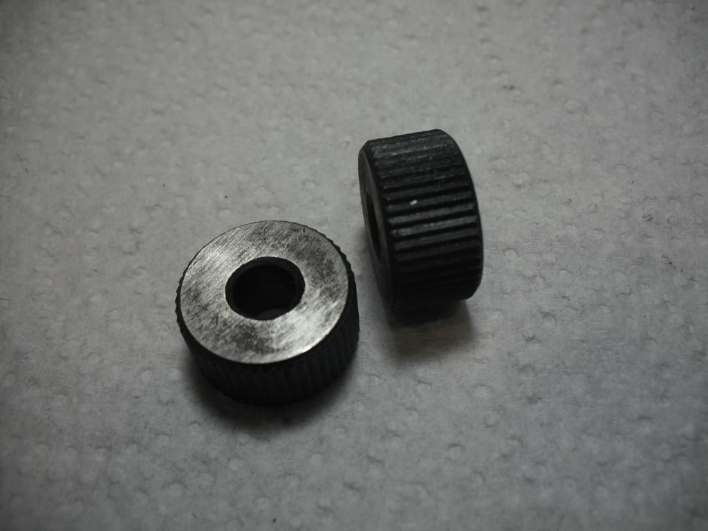
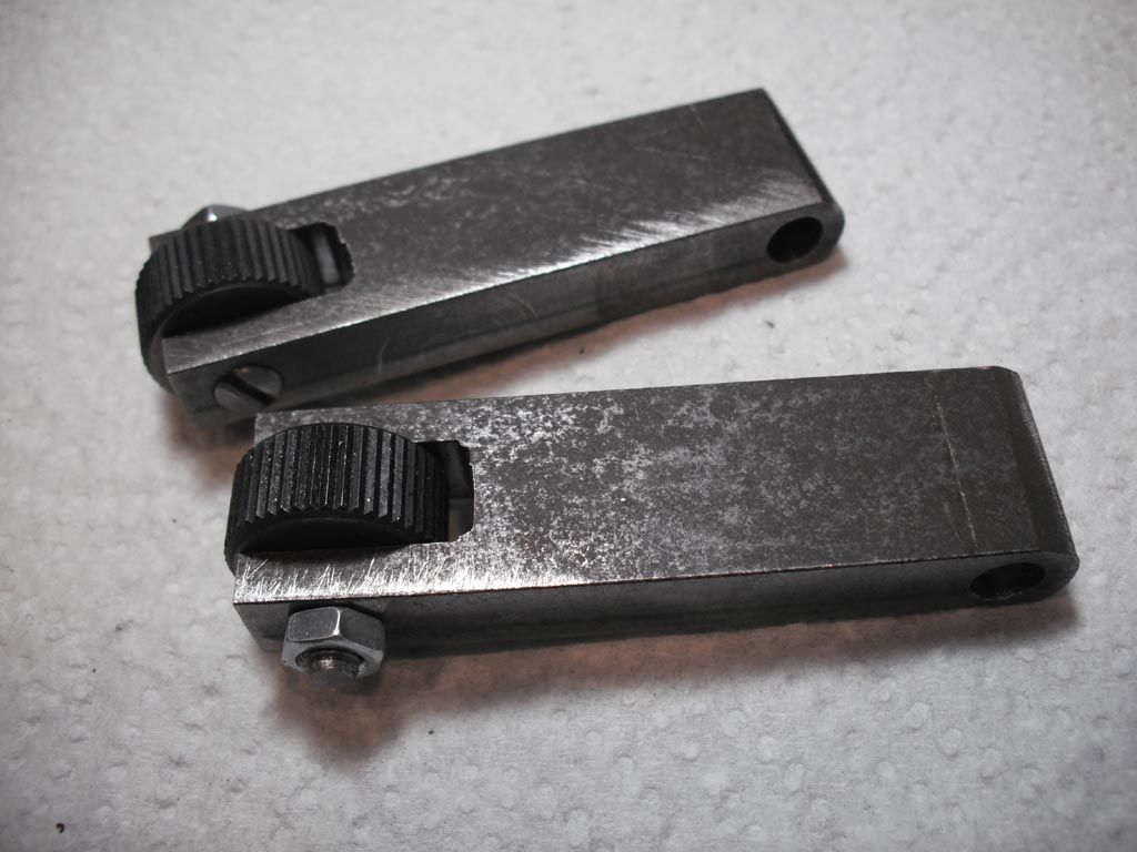
                                      I have had these for a few years. In fact I think I bought them at the last Harrogate Show. I have finally decided to do something with them.wheels.jpg

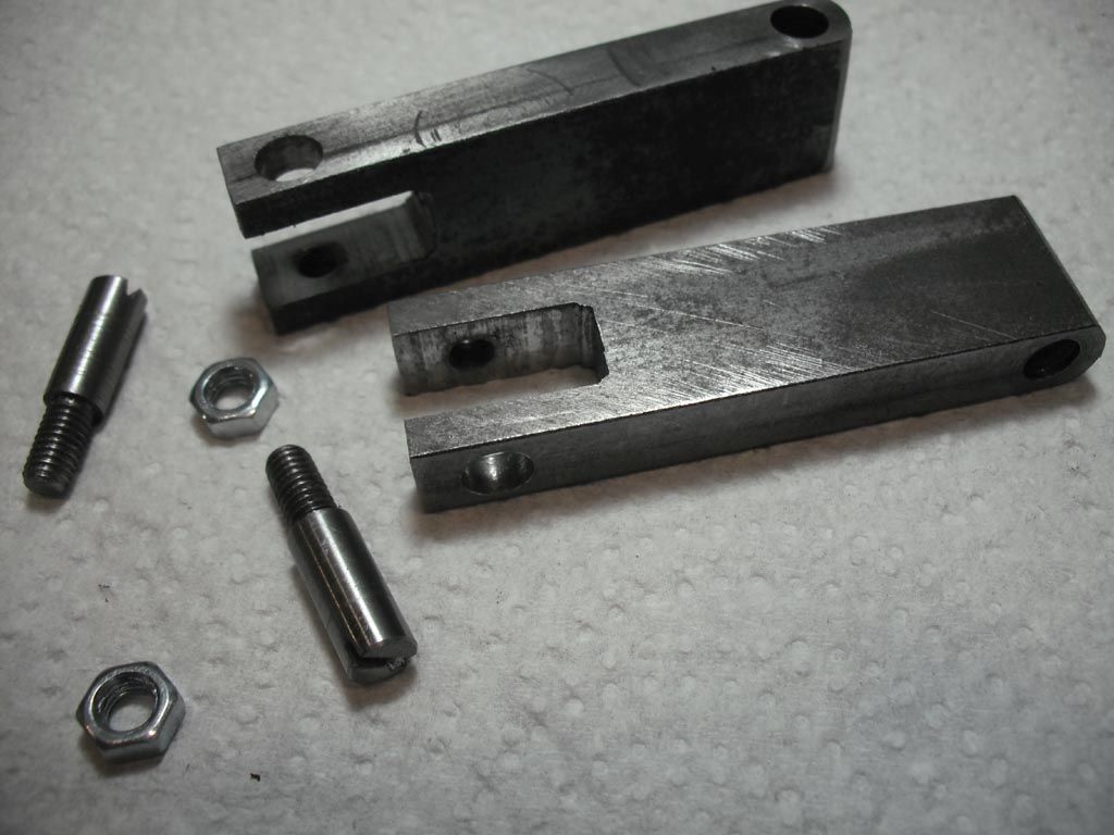
                                      I made some arms and retaining pins/axles. I decided to make them removable (unlike my bought one) so I can change the wheels if needed and also replace the pins if they become worn.

                                      arms1.jpg

                                      Assembled them to see if they fit properly.

                                      arms2.jpg

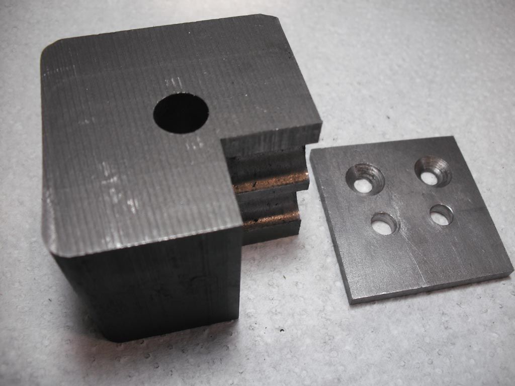
                                      I decided to make a Quick Change Tool POST to fit them to. No flimsy, hanging in the air gadgets for me.

                                      toolpost.jpg

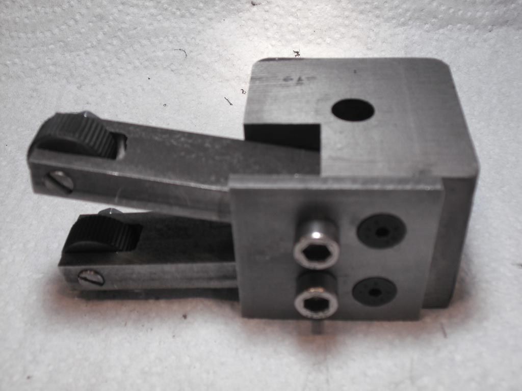
                                      Trial fit looking good. Just need to make the clamping assembly now.

                                      toolpost-knurl.jpg

                                      #476193
                                      Colin Heseltine
                                      Participant
                                        @colinheseltine48622

                                        Drained the antifreeze and changed all the coolant system hoses on my Caterham 1600 'K' series engine.. Now has nice shiny silcone hoses. Refilled with Millars Alpine Blue antifreeze. Hoping it was now going to be ready for when we are let out after lockdown once taxed but noticed that the exhaust manifold gasket leaking so now need to source a new one and fit it. Drat it.

                                        Colin

                                        #476196
                                        Ed Duffner
                                        Participant
                                          @edduffner79357

                                          Removed a Sycamore tree stump from the garden. Multiple trunks between Ø2.0" and 4". The main root was about 7" to 8".

                                          Started making a brcket to add a magnetic Z-axis scale on the the quill on my milling machine.

                                          Currenlty watching Live(I think) the Spacex launch.

                                          Ed.

                                          #476257
                                          Nigel Graham 2
                                          Participant
                                            @nigelgraham2

                                            Un filter perdu, a boiler still not yet mounted, and lights confirmed…

                                            '

                                            A somewhat lazy day but I cleaned the inside of the car, a wheelchair-converted Renault Kangoo, and finally replaced its broken mirror – I've booked the MoT for Wednesday. (I'd struck the mirror on an overhanging hedge-branch, losing half the glass; but enough remained, held in with lots of duct tape, to be useable.)

                                            I remembered an "advisory" from last year (year before?) about changing or cleaning the pollen filter I never knew it had. It's not called that in the Owner's handbook, which does include things my version does not have, but of course neither is its location given!

                                            The Internet yielded only fair to poor videos of changing the filter on the new Renault Kangoo. Still, they gave a clue as to where it might be.

                                            Thinking about it, the ventilation system could well be clogged because it emits far more noise than hot or cold air; and in some conditions demisting necessitates using a squeegee every few minutes. This though is a modern (ish) car, so Goodness only knows where they've hidden any of the system. As a neighbour put it, it would have been designed by people who came straight from university and had never serviced a car in their lives!

                                            '

                                            Tidied up, locked up, had tea and as relief from being baffled by what should be easy to find and service out on a vehicle, turned to my steam-wagon. I'm still trying to mount the boiler in the chassis, and this being a vehicle…

                                            The boiler is an odd shape, and has three rather thin-looking lugs on the vertical-cylindrical firebox of diameter is over 4 inches smaller than the distance between the chassis rails which are not parallel at that point.

                                            Also the smoke-box is not fastened to the boiler, as is typical on a traction-engine, but separate, as on a locomotive; and has to be drawn forwards to allow removing or installing the boiler in the frame.

                                            After a lot of experimenting, I've replaced the first version of the additional framework necessary, with one based on sculpting lengths of 50mm square steel tube to form combined channels and brackets. It will also support parts of the superstructure, and has to wiggle its way round the steering gear.

                                            To make arcuate cut-outs in two pieces of the channel I chain-drilled and filed them closely enough to try finish-machining them by boring-head. That didn't work very well, and it soon proved easier, safer and possibly quicker to finish-file to the line, and as accurately as necessary.

                                            Marking out those components in-situ was an intriguing exercise in placing a centre-point in the fresh air between the chassis sides. (In fact, on a length of 6mm thick strip G-clamped it to the frame, with its markings aligned to centre-punched and scribed data-points on the chassis.)

                                            Blue marking-out fluid does not give much contrast on hot-rolled steel, so for these I wire-brushed the surface rust off and gave them a thin coat of aerosol primer.

                                            '

                                            So tomorrow (Sunday?) Try to find the filter allegedly hiding deep in my car's Gallic recesses; and see if I can at least clean it out.

                                            '

                                            Took the car for its first run for 10 weeks yesterday; after a worrying time when It had forgotten how to start. A round trip of nearly 8 miles over to Portland and back put plenty of joules back in the battery and oil around the engine's innards, and flushed the fuel system through.

                                            I drove to the entrance to Portland Prison – there are fine views from there – and this finally nailed those pesky light you may remember had me puzzled a few weeks ago. I'd thought they might have something to do with the helicopter training base; but no, they are indeed traffic-lights at the prison's imposing main gate (from the site's original days as a fortress), and were obligingly going through their automatic cycles visible at night from my bedroom window a couple of miles to the North.

                                            #476261
                                            Steviegtr
                                            Participant
                                              @steviegtr

                                              Went out on the Ducati from Leeds to Skipton, Grassington, Over the Lindley wood reservoir (which was empty , frightening really for the time of year) Stump cross caverns which were closed. Pately bridge. . Feuston reservoir which was half empty. Otley & back home. 120 miles & an achy old bum. Did some more work on the new Koi pond build. Took some pics of the moon & the rocket launched from USA , with the new to me Nikon P1000. I need a good tripod. Not bad at 3000mm zoom , but at 12000 digital , impossible.

                                              Steve.

                                              #476266
                                              thaiguzzi
                                              Participant
                                                @thaiguzzi
                                                Posted by John Pace on 25/05/2020 17:26:02:

                                                Here is what i made to do the same job ,this balancing frame made from
                                                pieces of old steel channel bolted together some slots milled in each side
                                                for some hardened pieces of gauge plate.Fitted on the machine and
                                                ground flat some pieces of aluminium at each end to stop the wheel rolling
                                                off ,three jacking screws to level the frame .The edges should be ground to
                                                knife edge but the balancing shaft is soft so i left them square.
                                                Simple and little to go wrong just have to keep the edges clean.

                                                John

                                                wheel balancing.jpg

                                                John Hinkley,

                                                i had a specialist Triumph (Meriden – not Hinkley…) shop in the UK 1988-2003, and if the customer did'nt want to spring for a dynamic crank assembly balance (sent off), we offered in house static balancing. After making our own balance jigs of various copied designs inc your bearing version, and never being happy with the end result, we settled finally on John's version above. No bearings, just knife edges, used for many many years, highly accurate and repeatable.

                                                My 2 Baht's worth,

                                                regards,

                                                TG.

                                                #476280
                                                John Hinkley
                                                Participant
                                                  @johnhinkley26699

                                                  TG,

                                                  Thanks for that. It's pretty much confirmed the direction I'm going on this one. Tried the knife edge wheels described in my post with the CAD screenshot. That didn't work either, I'm going to try a pair of 6mmØ silver steel rods fixed to the top of the fixture and add three levelling screws for good measure. Failing that, I'm resigned to ordering some new material for the "scrap bin",

                                                  John

                                                  #476287
                                                  martin perman 1
                                                  Participant
                                                    @martinperman1
                                                    Posted by Nigel Graham 2 on 31/05/2020 00:51:26:

                                                    Un filter perdu, a boiler still not yet mounted, and lights confirmed…

                                                    '

                                                    A somewhat lazy day but I cleaned the inside of the car, a wheelchair-converted Renault Kangoo, and finally replaced its broken mirror – I've booked the MoT for Wednesday. (I'd struck the mirror on an overhanging hedge-branch, losing half the glass; but enough remained, held in with lots of duct tape, to be useable.)

                                                    I remembered an "advisory" from last year (year before?) about changing or cleaning the pollen filter I never knew it had. It's not called that in the Owner's handbook, which does include things my version does not have, but of course neither is its location given!

                                                    The Internet yielded only fair to poor videos of changing the filter on the new Renault Kangoo. Still, they gave a clue as to where it might be.

                                                    Thinking about it, the ventilation system could well be clogged because it emits far more noise than hot or cold air; and in some conditions demisting necessitates using a squeegee every few minutes. This though is a modern (ish) car, so Goodness only knows where they've hidden any of the system. As a neighbour put it, it would have been designed by people who came straight from university and had never serviced a car in their lives!

                                                    '

                                                    Nigel,

                                                    The usual trick is to access the filter either via the glove box, will need removing, or under the bonnet, passenger side, you may need to remove the valance bonnet seal to remove the valance, it maybe in their.

                                                    Martin P.

                                                    #476292
                                                    Iain Downs
                                                    Participant
                                                      @iaindowns78295

                                                      Curiously, Steve, I was walking round Lindley Wood reservoir (or near to be more accurate, it was like the M1!) and noticed the lack of water. As you say, quite concerning.

                                                      Iain

                                                    Viewing 25 posts - 301 through 325 (of 636 total)
                                                    • Please log in to reply to this topic. Registering is free and easy using the links on the menu at the top of this page.

                                                    Advert

                                                    Latest Replies

                                                    Home Forums The Tea Room Topics

                                                    Viewing 25 topics - 1 through 25 (of 25 total)
                                                    Viewing 25 topics - 1 through 25 (of 25 total)

                                                    View full reply list.

                                                    Advert

                                                    Newsletter Sign-up