Some more experiments with the Rattle Dampers..
Paul White asked some difficult questions – How to base a 'rattle' damper design on mathematical foundation, so that led to a whole divergent exercise, one which I am happy to say, I simply gave up on! I managed to develop a convincing mathematical model of the stepper motor, and the toothed belt compliance , but a model of the rotary table, worm gear, and friction assumptions became awkward, And then trying to derive a model for variance in stepper torque related to table friction versus stepper mechanical position against the torque vector….
It was easier to make a half dozen variations of the rattle damper and test them!!
What I found- ( slugs always 10mm diameter, 18mm long)
1). Keeping the slug size constant and increasing the diameter of the slug hole in the flywheel from 11mm to 14mm reduced hugely the tendency for step-loss at low RPM ( sub 30 rpm), but adversely affected the ability to avoid stall at high RPM.
2). Increasing the diameter of the the flywheel in 1) above, to keep its weight the same as a flywheel with non-increased slug-holes had no obvious positive or negative effect. The increase was done by simply adding a sleeve of material over the outer of the flywheel.
3) A flywheel of 60mm diameter, with 6 slug holes of 11mm, centered on a 22.5mm radius was the benchmark and worked well, as previously described. Bringing the slug holes closer to the center, on a radius of 15mm, resulted in the high speed end being unaffected ( worked well), but the low speed end was almost as bad as with no damper fitted.
4) A 50mm diameter wheel was made, with 11mm slug holes on a 17mm radius was made. The slugs were 10mm diameter x 18mm. made in lead. This wheel performed VERY well, both at low rpm and high rpm. However, after a 15 minute cycle running from 0 rpm to 100rpm and back, each cycle taking 30 seconds, the lead slug had reduced to 9.8mm diameter (approx..) and the length had increased to almost touch the sides of the covered hole.
Obviously the slugs are being hammered! Just shows the amount of harmonic vibration in the stepper cycle. A huge advantage of the lead slug – dead quiet! No rattle at all. However, the slug would most likely need to be encased in a thin walled steel tube to prevent slug deformation – Although I suspect that thin tube would wear through fast..
To see the wear effects, I ran the 60mm benchmark flywheel with steel slugs for 60 minutes, 30 sec ramp up, 30 sec ramp down, with a 15 sec dwell at 1000 rpm. On completion I removed the aluminium side cover ( keeping the slugs in place) and each cavity was black; a microscopically fine black powder covering the entire hole and slug. Collecting all the powder in one hole amounted to maybe a 1/4 of a match head worth..
This implies a high wear rate, although I guess this would be of little consequence in our workshops where the use is infrequent and of low period..
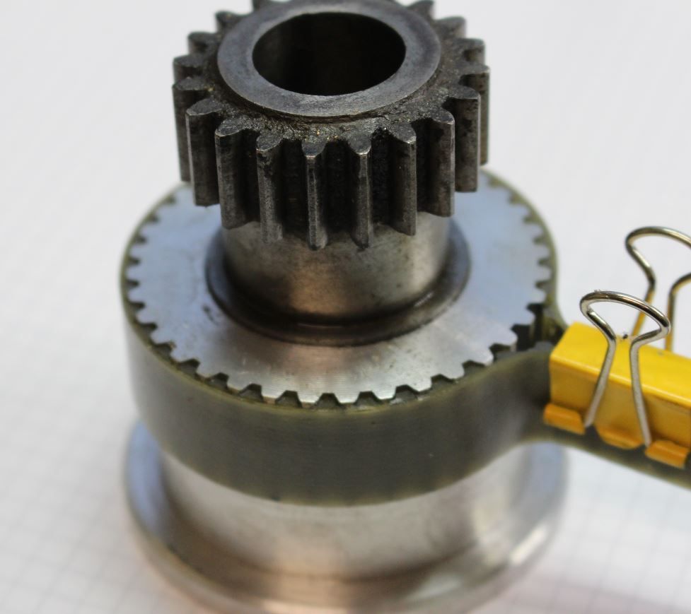
I will most likely go for a lead filled tube slug, and the smaller diameter wheel – it is easier to get a belt cover over it all in my setup
Murray, you are on the right rack – The slugs appear to form a pendulum damper, being located in the centred position ( of the outer periphery of the hole) by centrifugal force, although this only applies to the medium, upper and higher speeds – at low speeds the slugs just seem to bang from side to side, and I suspect their benefit comes mainly from an almost random perturbation of the stepper resonance, in effect breaking up the resonance.
Such a simple device, with some amazing benefits, but its simplicity certainly belies the underlying complexity!
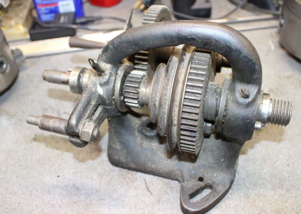
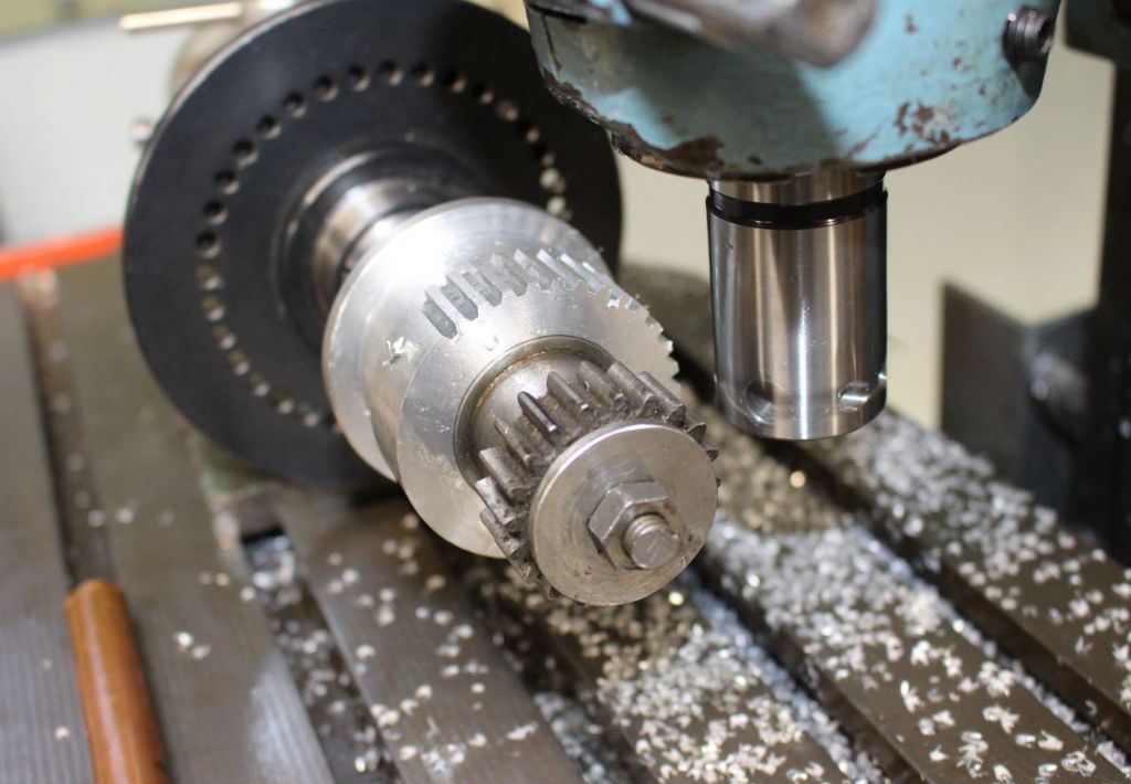
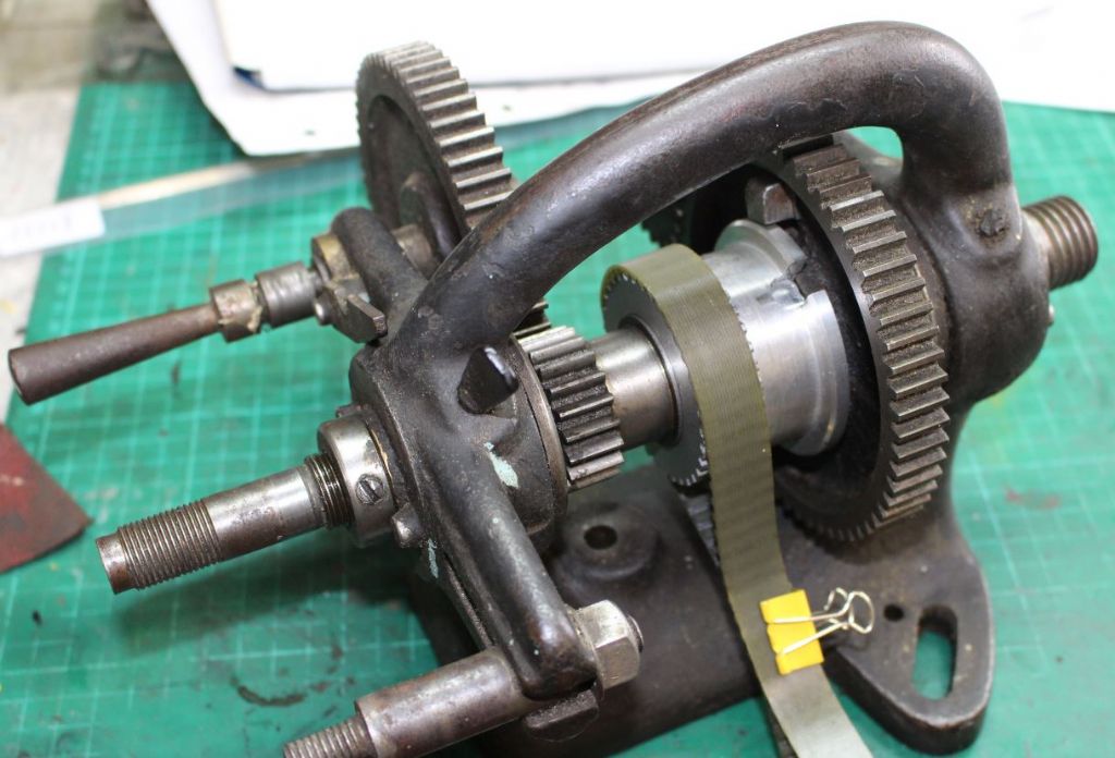
And I was just doing some software for a gear hobber for some friends…
Joe
Tim Taylor 2.


