Warco WM16 Powerfeed

Advert

Warco WM16 Powerfeed

Home Forums Manual machine tools Warco WM16 Powerfeed

Viewing 22 posts - 1 through 22 (of 22 total)
  • Author
    Posts
  • #427827
    Chris Buxton
    Participant
      @chrisbuxton55939

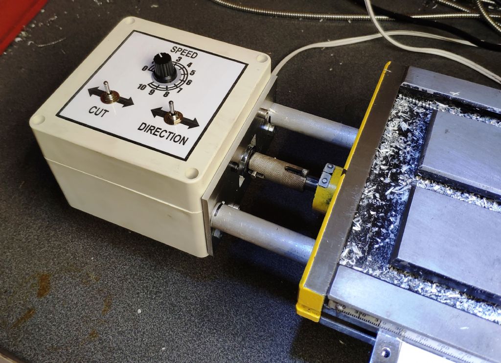
      I've just acquired a Warco WM16 milling machine and wanted a X axis power feed for it.

      I came across Mikes workshop **LINK** and liked his approach.

      I've beefed up the motor/components to cope with the larger mill.

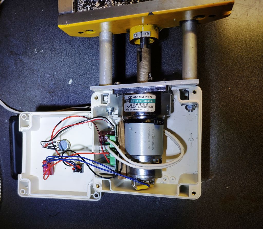
      All the components were purchased off fleabay for around £45.

      24v 150rpm gearbox motor 35W peak.. Runs at 11W on fast return on my mill.

      24V 3A power supply unit

      120X120x90mm Waterproof plastic project box

      20A PWM Speed controller Module

      Couple of switches

      The power supply is adjustable slightly via a pot, so I've set it at 28v . The lead screw is a 2mm pitch and with this motor & gearbox gives 35cm/min fast travel. It slows down to absolute crawl yet still has enough torque to cope. The Power supply is screwed to the wall so the cable to the powerfeed is a safe low voltage.img_20190904_183844.jpg

      img_20190904_184642.jpg

      Advert
      #13631
      Chris Buxton
      Participant
        @chrisbuxton55939
        #428471
        David Canham
        Participant
          @davidcanham77137

          Hi Chris,

          I am one post above you also with zero input so i thought i'd say hello. Good luck with your model engineering yes

          David.

          #428472
          JasonB
          Moderator
            @jasonb

            Steve, do you know whet the gear ratio is on the gearhead to give the 150rpm at 24V?

            #428479
            Stuart Bridger
            Participant
              @stuartbridger82290

              Nice project, inspiring. Especially given the cost of original equipment units.

              #428480
              Ron Laden
              Participant
                @ronladen17547
                Posted by JasonB on 10/09/2019 19:58:59:

                Steve, do you know whet the gear ratio is on the gearhead to give the 150rpm at 24V?

                Jason, If its the motor I think it is (approx 5000 rpm) then 33/1 but dont quote me on that, there are a number of models in this range 12 volt and 24 volt and the spec given is often not that accurate.

                #428530
                Stuart Bridger
                Participant
                  @stuartbridger82290

                  Hi Chris, how did you work out how much to "beef up" the original design?
                  Also having read Mike's article, I did find his rapid/return feed logic a bit difficult to get my ahead around, but i guess it makes sense when you understand it.

                  #428534
                  John MC
                  Participant
                    @johnmc39344

                    I've been looking at this design for a power feed for a mill I'm working on. Two reservation, firstly is that there is no means of instantly disengaging the drive to the table. Secondly, electrical stops, how accurate are they? OK for limiting the overall feed. Does the motor stop instantly or is there a finite period of slowing down?

                    Neither of these are "show stoppers" for me, I'll sort out a lever operated dog clutch. As for reliable/accurate stops I can work around that one, disengage the drive near to where I want to stop the feed and manually feed up to a point on the dial/DRO.

                    John

                    #428574
                    Chris Buxton
                    Participant
                      @chrisbuxton55939
                      Posted by Stuart Bridger on 11/09/2019 10:57:47:

                      Hi Chris, how did you work out how much to "beef up" the original design?
                      Also having read Mike's article, I did find his rapid/return feed logic a bit difficult to get my ahead around, but i guess it makes sense when you understand it.

                      The amount of extra beef applied was really in the end… determined by best bang for buck. That 150rpm gearbox motor combo is £20 .. after that the price of them quadruples. 24V power supplies are dirt cheap £7, 20A PWM module £4

                      I figured the more power the better for torque at very low rpm.

                      I determined the torque of the smaller and slower 60rpm motor/gearbox used originally by Mike, that apparently struggled a little under some circumstances. And then went bigger until my Yorkshire wallet complained.

                      #428577
                      Chris Buxton
                      Participant
                        @chrisbuxton55939
                        Posted by John MC on 11/09/2019 11:54:21:

                        I've been looking at this design for a power feed for a mill I'm working on. Two reservation, firstly is that there is no means of instantly disengaging the drive to the table. Secondly, electrical stops, how accurate are they? OK for limiting the overall feed. Does the motor stop instantly or is there a finite period of slowing down?

                        I haven't implemented the stops as of yet. On the website link its stated that stop accuracy is 0.01mm, which would be more than accurate enough for me.

                        The motor does stop instantly at cutting speeds. I may add a panic stop button in the future if I feel the need.

                        #428596
                        not done it yet
                        Participant
                          @notdoneityet

                          I would think there would be a difference in stopping time between feed speeds and fast traversing due to the inertia?

                          Not the same drive, but the table power feed on my Centec 2B certainly doesn’t stop instantaneously. There is likely a programmable brake on the VFD (if I wanted to use it), but the table does not move far at switch off. The important thing is consistency – like how far it takes to stop at the same feed rate and cut. I would think a mechanical trip would be better – my lathe is very reproducible when using the carriage trip.

                          Question might be as to whether there is a brake on the motor used in this design.

                          #434664
                          Trevorh
                          Participant
                            @trevorh

                            Hi

                            I have gone the Purchased power feed route and bought one of these from Warco for my WM16

                            2019-10-12 08.00.26.jpg

                            and as expected as its mean't for a WM18 I need to change a few things

                            I will post as I go

                            Trevor

                            #434666
                            Trevorh
                            Participant
                              @trevorh

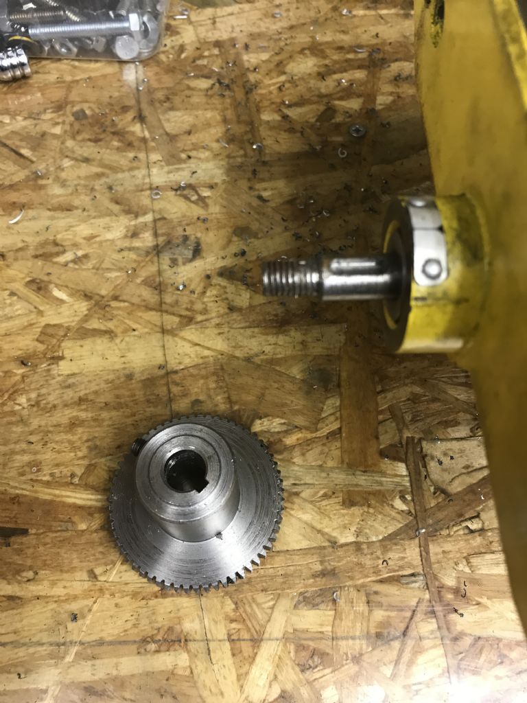
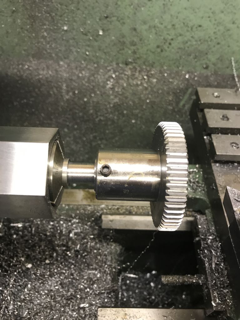
                              So with the handle removed the first problem was the shaft size vs the gear bore

                              2019-10-12 08.01.43.jpg

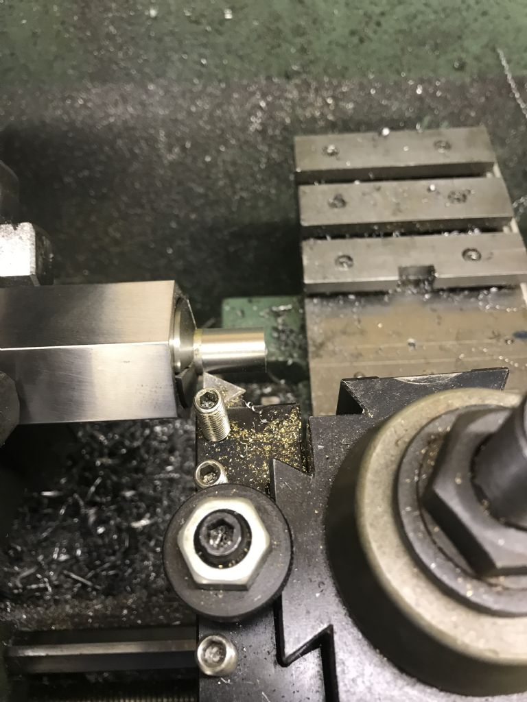
                              not a sliding fit – more a throw on from a long distance so I machined a bush

                              2019-10-12 07.59.59.jpg

                              This at least got the gear fitted nice and true

                              2019-10-12 08.24.20.jpg

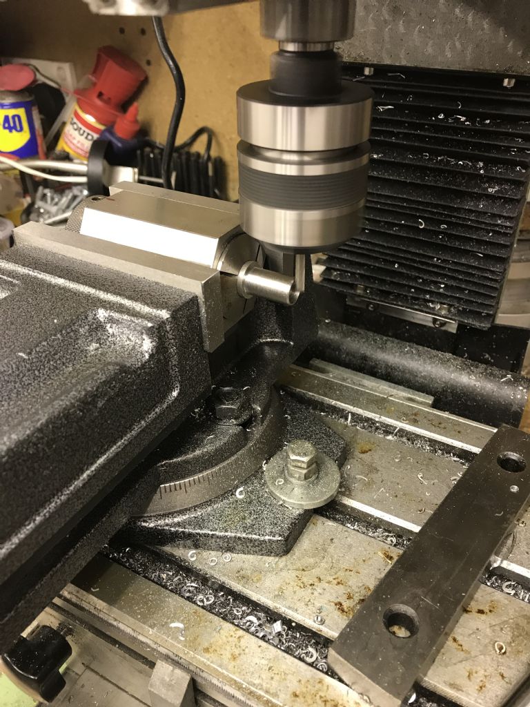
                              next keywayed the bush keeping it in the collect

                              2019-10-12 13.24.58.jpg

                              next onto the actual main body but thats for another day

                              trevor

                              #434674
                              mechman48
                              Participant
                                @mechman48

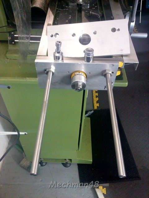
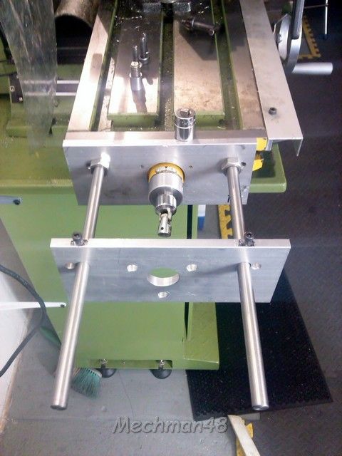
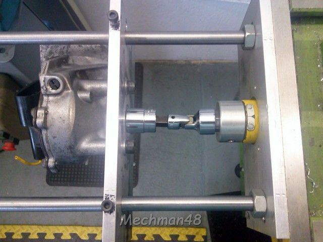
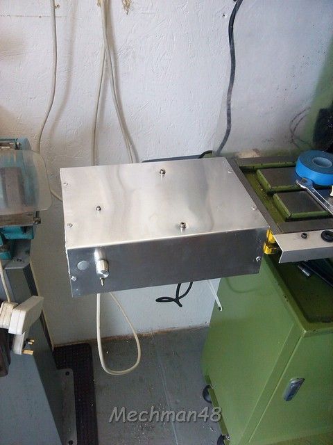
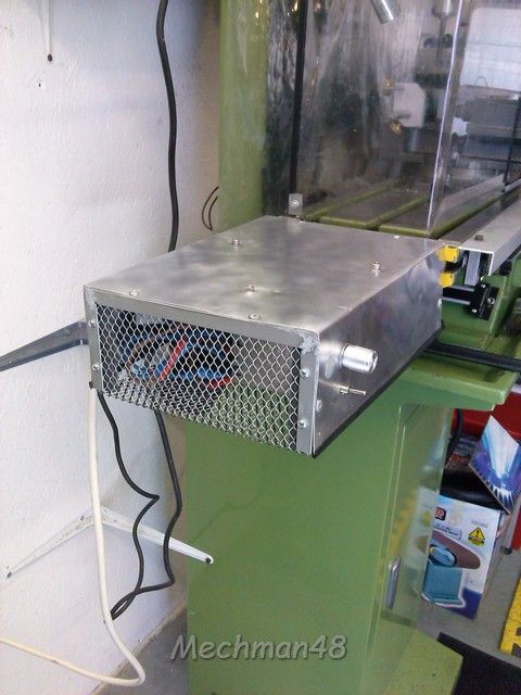
                                I have fitted a similar system to my WM16 using a 12v wiper motor free gratis, a 240/110v to 12v dc transformer eBay, approx £12, a PWM with on/off switch, eBay again, approx. £5, 2 pieces of 10 mm aluminium plate free gratis, some bit's n' bobs from scrapbinium box, universal joint from defunct socket set, stainless steel sheet from skip diving, 'e voila' a working 'X' drive. It doesn't have fast forward/reverse ( yet thinking ) but on full PWM speed it copes very well, can't remember what mm/min it does at the mo'.

                                x axis drive (1).jpg

                                x axis drive (2).jpg

                                x axis drive (4).jpg

                                x axis drive (6).jpg

                                x axis drive (7).jpg

                                George.

                                #435142
                                Trevorh
                                Participant
                                  @trevorh

                                  Hi George, very nice, honestly yours would have been beyond my abilities, so this is what I ended up with

                                  2019-10-28 09.35.07.jpg

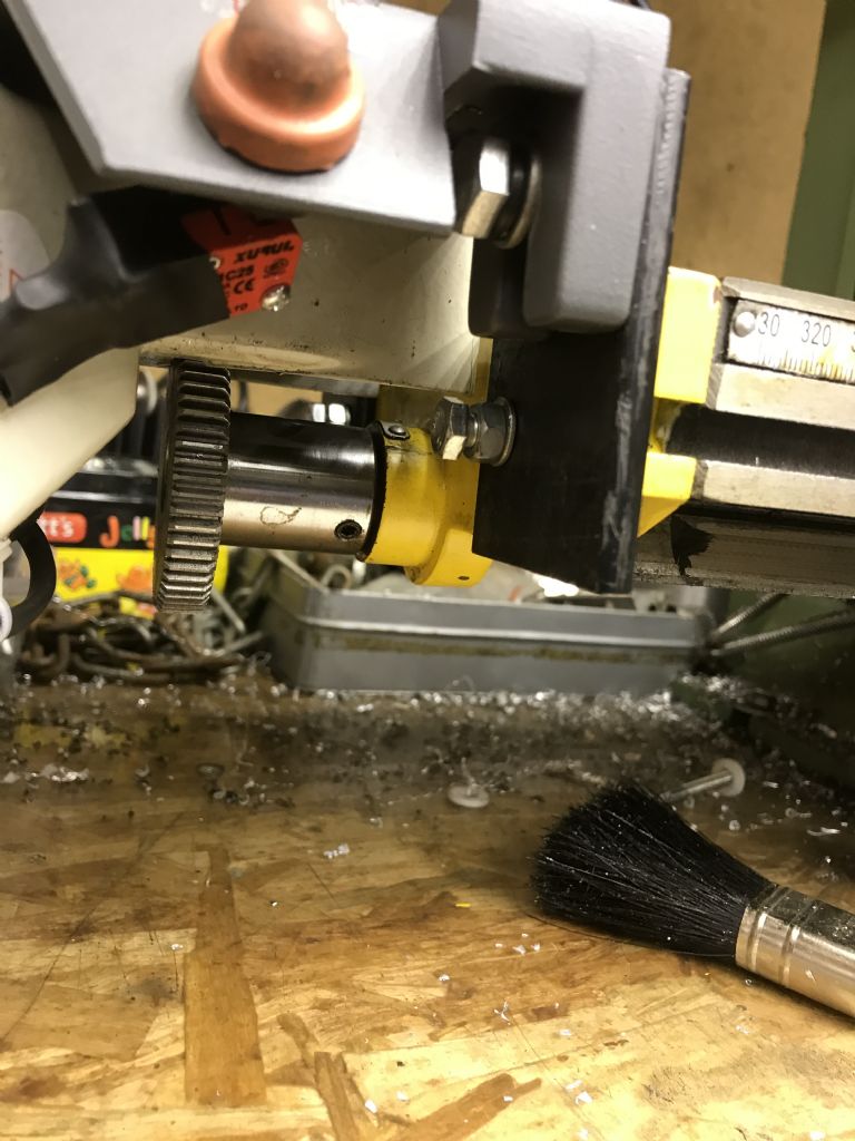
                                  just had to add a stand off plate to get the drive gear in the right position as shown below

                                  2019-10-28 09.34.55.jpg

                                  and we were good to go

                                  Not sure that I am going to fit the auto return end stops and switching gear tho' 1. takes up quite a lot of room 2. I will always be there operating it so the chances of it traversing that far is quite slim

                                  Trevor

                                  #435163
                                  mechman48
                                  Participant
                                    @mechman48

                                    Looks the biz' Trev, nicely done.

                                    George.

                                    #435175
                                    John MC
                                    Participant
                                      @johnmc39344
                                      Posted by Chris Buxton on 11/09/2019 18:17:23:

                                      Posted by John MC on 11/09/2019 11:54:21:

                                      I've been looking at this design for a power feed for a mill I'm working on. Two reservation, firstly is that there is no means of instantly disengaging the drive to the table. Secondly, electrical stops, how accurate are they? OK for limiting the overall feed. Does the motor stop instantly or is there a finite period of slowing down?

                                      I haven't implemented the stops as of yet. On the website link its stated that stop accuracy is 0.01mm, which would be more than accurate enough for me.

                                      The motor does stop instantly at cutting speeds. I may add a panic stop button in the future if I feel the need.

                                      Thinking some more over the question of stops. I believe that electrical switches that limit the overall length of feed are important. I would suggest that a quite considerable the torque is applied to the lead screw. If it was not disengaged before the limit of travel is reached then some damage will be done. Something may "give" in the motor/gearbox, worse still damage to the lead screw and nut. Even worse still the work table on these very lightweight machines could be twisted.

                                      With no limit switches it would only take a momentary distraction , then the damage is done!

                                      John

                                      #435194
                                      Trevorh
                                      Participant
                                        @trevorh

                                        Hi John

                                        That is a valid point and under normal circumstances I would fit said switches but

                                        1. I have the extended bed length and together with the max speed feed rate it takes several seconds to traverse one end to the next

                                        2 the lost room taken up by the location of the reversing switch is quite excessive when taking into account I only work on small projects

                                        Even on rapid traverse it still takes approx 15 seconds to travel full distance

                                        So for me its just not worth the hassel vs the rewards by paying attention to what I am doing

                                        trevor

                                        #435257
                                        Chris Buxton
                                        Participant
                                          @chrisbuxton55939

                                          I've found that I have a "natural" limit switch in my design and so the limit switches for end of travel are not so important. I found this out due to a plastic box getting underneath the rotating hand wheel whilst under power. The power from the motor under high torque conditions overwhelmed the speed controller or 3A power supply causing it to shutdown in a kind of PWM mode. …. Handy that .

                                          Edited By Chris Buxton on 30/10/2019 12:07:46

                                          #435303
                                          mechman48
                                          Participant
                                            @mechman48

                                            Blew the fuse then Chris face 22.

                                            George.

                                            #435379
                                            Chris Buxton
                                            Participant
                                              @chrisbuxton55939
                                              Posted by mechman48 on 30/10/2019 17:57:57:

                                              Blew the fuse then Chris face 22.

                                              George.

                                              No, just been experimenting with it. Its the power supply which cuts in and out… It must have some over current detection. Its a great safety feature

                                              #435391
                                              mechman48
                                              Participant
                                                @mechman48

                                                Thanks Chris, didn't know that, I have a PWM fitted to my set up so it's something to bear in mind.

                                                George.

                                              Viewing 22 posts - 1 through 22 (of 22 total)
                                              • Please log in to reply to this topic. Registering is free and easy using the links on the menu at the top of this page.

                                              Advert

                                              Latest Replies

                                              Home Forums Manual machine tools Topics

                                              Viewing 25 topics - 1 through 25 (of 25 total)
                                              Viewing 25 topics - 1 through 25 (of 25 total)

                                              View full reply list.

                                              Advert

                                              Newsletter Sign-up