Vintage lathe cross slide adjustment

Advert

Vintage lathe cross slide adjustment

Home Forums Manual machine tools Vintage lathe cross slide adjustment

Viewing 12 posts - 26 through 37 (of 37 total)
  • Author
    Posts
  • #516110
    Howard Lewis
    Participant
      @howardlewis46836

      Hi Arthur,

      In my experience, having made at least five, (For toolbits varying from 1/8 to 5/16" ) before buying "The genuine article" from Eccentric Engineering, they work extremely well, capable of sliding or facing without problems, and with a fine feed, giving a good finish. (Matching a shear tool )

      There have been at least two designs published in M E W.to make your own, both for 1/8 toolbits, and the simple jig for sharpening.

      The first one that I made involved milling at compound angles, and is easy to get wrong!

      The second design is simpler because it involves milling the toolholder shank at an angle, leaving only the groove for the toolbit to be milled at an angle. In this way, you are only milling in one plane at a time.

      Sharpening is easy, since with a simple jig there is only one face to grind, the clearance angles are provided by the holder, and the angles at which the bit is held.

      Downsides?

      Some may regard the use of HSS bits (rather than carbide tips ) as a downside, but an elderly machine is not suitable for the speeds and feeds needed to get the best from carbide.

      Heavy Interrupted cuts, such as on square or hexagon material can hammer the tool down in the holder. But that is probably the warning sign that you are pushing your luck!

      You will need to make a Centre Height Gauge, so that the bit can be set to centre height with minimum of effort.

      Like others on here, it is my standard tool, used for finishing. Having said that I have taken heavy cuts, the onset of chatter telling that the limit has been reached or exceeded. .

      At least two of us have even made a tangential flycutter for use on the mill, if that is any sort of testimonial.

      Howard

      Advert
      #516202
      Bazyle
      Participant
        @bazyle

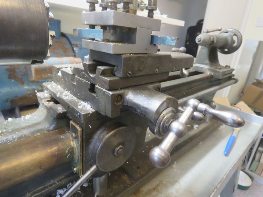
        Arthur, glad you are making progress. Back to identifying your lathe I notice the cross slide front extension is not per the normal RandA style having more in common with the later Myford design so interesting. Possibly an owner modification but the casting looks professional. More photos pleas. The dial is probably a modification as many lathes had none or small ones like on your topslide so better ones were made available. The scallop on the casting for the fiducial line looks to go lower to align with a small orignal one.
        Instead of trying to make a 62.5 dial consider twice that on a much bigger dial – the largest you can fit. No need to engrave it just use one of the many online dial programs to print one and glue it to a plain disc. Perfectly adequate for the occasional use you say you are making of the lathe.

        #516316
        Howard Lewis
        Participant
          @howardlewis46836

          Whereabouts are you located?

          If you cannot make a dial (Graduating it may be the problem The lathe provides the facility to make a blank dial of suitable dimensions ) Someone may be near, and prepared to graduate it for you.

          For a HV6 Rotary Table with a 90:1 ratio, there are no exact settings for 62.5, or for 133 divisions.

          However, the errors are pretty small, (For instance, 18.04 holes on a 41 hole plate, for 62.5 divisions vs the 18 actually used ) By the time that the error has been reduced by a factor of 90, it becomes pretty insignificant (0.04 / 18.04 = 0.00221 Divide by 90 and the error becomes 0.000002464 of a division., or 0.00001419 degrees!

          Manufacturing errors will exceed this.

          Howard

          #516348
          Arthur Moore
          Participant
            @arthurmoore87122

            Hello Howard and Bazyle,

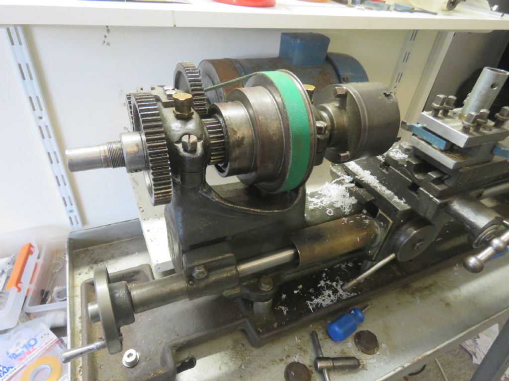
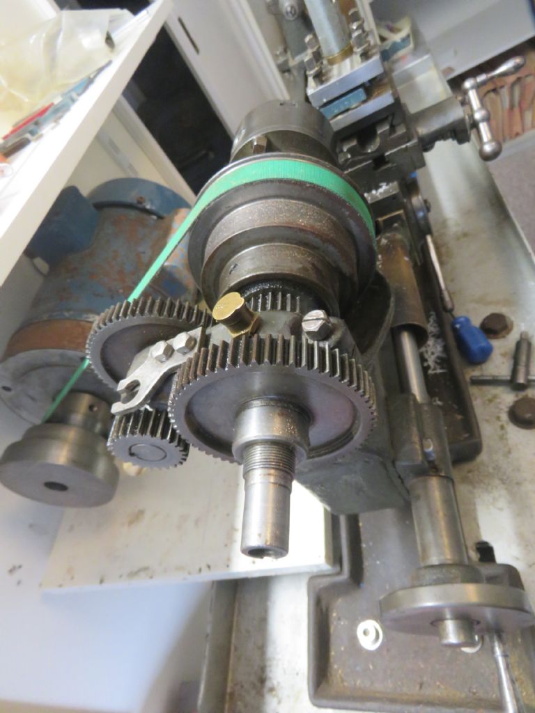
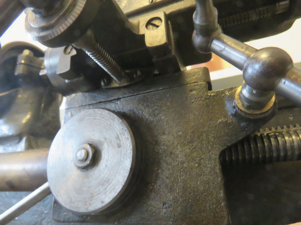
            I enclose some more photos as requested.

            headstock 1.jpg

            headstock 2.jpg

            cross slide l.jpg

            cross slide r.jpg

            y feed screw.jpg

            This is an underneath view of the Y lead screw.

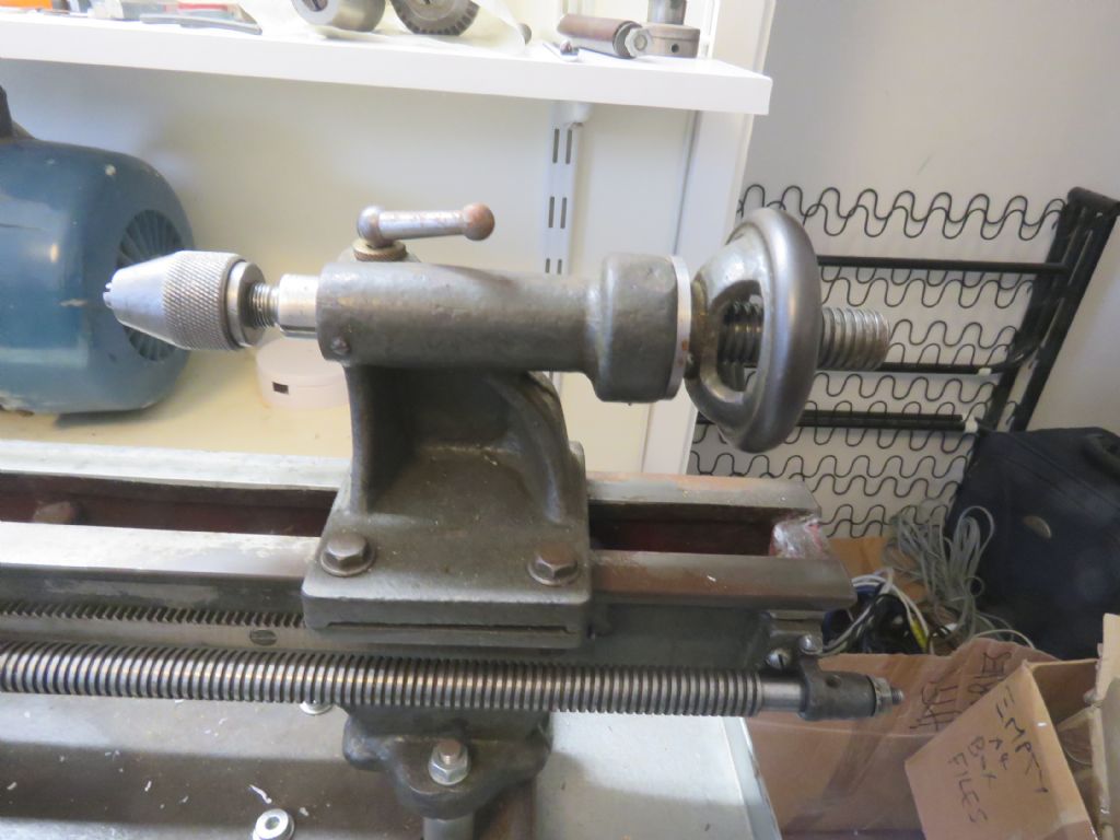
            And just for completeness – the tailstock:

            tailstock.jpg

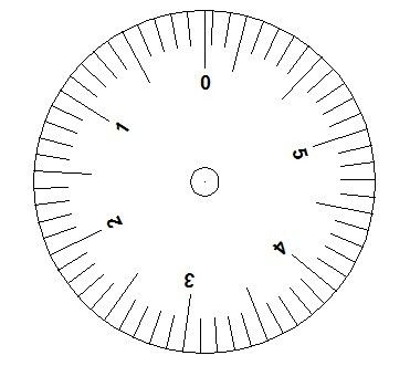
            Concerning the dial, I am a member of Nottingham Hackspace which has an 80W laser. It won’t cut aluminium, but it will engrave anodised aluminium, which removes the anodising. I have never tried it, but Autocad will do a polar array with any angle or number of divisions.

            I enclose a sketch which I have just produced on Autocad, so is this the sort of thing I would need?

            lathe dial sketch.jpg

            We move into tier 4 tonight, so Hackspace will be shut down, but I will try it next time I can get into the space and see if I can etch a dial, which I will then just need to cut to size.

            Arthur

            #516368
            Howard Lewis
            Participant
              @howardlewis46836

              I was envisaging a dial with the graduations on the circumference.

              But if there is no space for such a dial, your face dial (basically a thin disc ) would be OK, with a pointer (Fiducial mark if you want to be pedantic ) at the outer edge. Similar to my memory of the Myford ML1, ML2, ,ML3 and ML4 set up, I think.

              Within reason, the larger the diameter, the better, since any "interpolation" / guessing, between lines would be easier and or accurate, because the line spacing will be greater.

              Howard.

              #516461
              Rob McSweeney
              Participant
                @robmcsweeney81205

                Rather than fitting a dial, have you considered a digital readout? Not too expensive these days, or you can modify a digital vernier for a low-cost version. You can then swap between metric and imperial as you wish.

                And, if you do find yourself bitten by the bug and upgrade in a while you can transfer it to another machine.

                #516503
                Arthur Moore
                Participant
                  @arthurmoore87122

                  Hi Rob,

                  Yes – a digital readout is certainly the best solution. We have it on the Bridgeport miller at Hackspace and it is great. Just touch the tool to the surface, zero the reading and it is so easy to take off the exact amount with no mental arithmetic.

                  I have looked at some of the videos for fitting the DRO scales and it does not look too difficult. The only thing I wondered is how easy is it to drill into the casting and to tap the holes? Will a normal HSS or cobalt tip drill do it?

                  Regards, Arthur

                  #516507
                  Howard Lewis
                  Participant
                    @howardlewis46836

                    HSS drill and tap will easily deal with cast iron. It will be a slightly dirty job, because of the graphite in the cast iron. Wipe /suck / magnet it away from the machine ASAP. Despite the graphite, C I dust will cause wear when it gets in where it shouldn't.

                    If you are wary of how to keep the tappings square to the surface, make up a bush (tapping size drill ) before, and use to steady / guide the drill.

                    When all the holes have been drilled, you can then, tap the hole in the bush so that it becomes the tapping guide.

                    (Using the lathe should keep the drilling, and the tapping of the bush square to the face of the bush. )

                    Howard

                    #516508
                    Arthur Moore
                    Participant
                      @arthurmoore87122

                      Thanks for the helpful suggestion.

                      Best wishes to all on the forum for a safer and much happier New Year

                      … and for us all to be able to visit a model engineering exhibition in the coming months.

                      Arthur

                      #516510
                      Roger Best
                      Participant
                        @rogerbest89007

                        And a happy new year to you too Arthur.

                        Following the predictable habit of not dropping a line of conversation I note that some DRO are almost as cheap as calipers, so almost a no-brainer for someone who is not an experienced machinist and finds dials difficult to read. (That would be me for instance.)

                        ARC cheap readout

                        #516521
                        Arthur Moore
                        Participant
                          @arthurmoore87122

                          Hi Roger,

                          I agree the DROs are virtually as cheap as calipers these days. The only disadvantage seems to be if you put it on the headstock side it risks filling up with swarf and coolant, and if it is on the tailstock side you have to extend the tailstock feed, which may reduce accuracy?

                          Arthur

                          #516542
                          Roger Best
                          Participant
                            @rogerbest89007

                            Yes, somewhere over the back seems to be the best place, somewhere near your motor in your case. frown

                          Viewing 12 posts - 26 through 37 (of 37 total)
                          • Please log in to reply to this topic. Registering is free and easy using the links on the menu at the top of this page.

                          Advert

                          Latest Replies

                          Home Forums Manual machine tools Topics

                          Viewing 25 topics - 1 through 25 (of 25 total)
                          Viewing 25 topics - 1 through 25 (of 25 total)

                          View full reply list.

                          Advert

                          Newsletter Sign-up