VFD to lathe motor connector

Advert

VFD to lathe motor connector

Home Forums General Questions VFD to lathe motor connector

Viewing 13 posts - 26 through 38 (of 38 total)
  • Author
    Posts
  • #451888
    Robert Atkinson 2
    Participant
      @robertatkinson2
      Posted by old mart on 12/02/2020 17:21:06:

      As long as you always remember to do things in the correct order.

      1. Connect the vfd to the motor.

      2. Connect the vfd to the mains and switch on. Run the motor.

      3. Power down the motor using the vfd controls.

      4. Turn off the mains.

      5. Disconnect the vfd from the motor.

      If you do this every time no harm will be done.

      And how is anyone ele supposed to know this? If it's acessible it has t be safe without any special proceedures. CEE or HAN +PE connectors are good choices. Another option, similar to the HAN A is the Hirshman ST series. The STAK3N https://uk.farnell.com/hirschmann/stak3n/rectangular-receptacle-3-pe-way/dp/1176412
      and
      STASEI3N https://uk.farnell.com/hirschmann/stasei3n/plug-panel-3-e-way/dp/495025
      make a auitable 16A pair for under £20.

      The metal shell GX20 "microphone" connectors must NEVER be used fo any voltage over 50V, the design is not safe. That's apart from the fact that the cheap ones may not be well made. Only £15 extra for safety.

      Robert G8RPI.

      Advert
      #451901
      old mart
      Participant
        @oldmart

        I was assuming that the op just wanted to use the machine as a sole operator, everything changes if it is for public use.

        The motor and vfd on the museums Tom Senior light vertical can be disconnected if the machine is to be dismantled. The plug on the motor cable has five pins to include an earth and screening. The matching bulkhead socket is on the side of the metal vfd case. A similar plug and socket with a different pin count is for the remote kill switches, and a kettle lead and socket is for the mains into the vfd. All of these connectors are rated well above the working voltage and current. The vfd to motor connection has a seal and warning label to deter inadvertent uncoupling which would only be hazardous to the wellbeing of the inverter. These connections are out of sight at the back of the vfd box. The circuit diagram is in the mill data paperwork. The vfd/motor plug and socket are rated 500V and 30A which is adequate for a 1hp motor.

        Edited By old mart on 12/02/2020 20:03:30

        #451909
        SillyOldDuffer
        Moderator
          @sillyoldduffer
          Posted by Robert Atkinson 2 on 12/02/2020 18:16:27:

          Posted by old mart on 12/02/2020 17:21:06:

          As long as you always remember to do things in the correct order.

          1. Connect the vfd to the motor.

          2. Connect the vfd to the mains and switch on. Run the motor.

          3. Power down the motor using the vfd controls.

          4. Turn off the mains.

          5. Disconnect the vfd from the motor.

          If you do this every time no harm will be done.

          And how is anyone ele supposed to know this? If it's acessible it has t be safe without any special proceedures. CEE or HAN +PE connectors are good choices.


          Robert G8RPI.

          An interesting challenge, designing interlocks for safety!

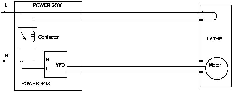
          My suggestion: an extra pair be added that loops back to enable a contactor. Suggested circuit:


          safety.jpg

          Earth omitted for clarity. This would stop the VFD powering up unless the lathe was connected. Is it good enough? Designing safety interlocks isn't my thing!

          Dave

          Fixed circuit labelling error!

          Edited By SillyOldDuffer on 12/02/2020 20:24:05

          #451918
          old mart
          Participant
            @oldmart

            Excellent from a safety point of view, but as in a lot of ideas which are good in theory, it has a possible drawback. The power in wires need to be very well shielded from the vfd to motor ones. That would make a single plug and socket problematical. Having the two circuits ganged together rigidly, but held apart to keep the interference low could be done. If the plug and sockets were at the power box end, the mains loop would not have to extend to the lathe

            #451919
            Gene Pavlovsky
            Participant
              @genepavlovsky

              Nigel, I think what you propose makes sense. Since English is not my native language, it took me a bit of time to figure out what is meant by the terms flying lead, chassis plug (I would call this one panel mount socket) and cable mount socket (I would call this plug). But in the end I got your point, and generally it looks like the solution in the picture I posted in the original post. Perhaps with 5 pins instead of 4, the fifth being used to terminate the screen.

              I'd like to reiterate that the lathe will indeed only be used by me in my small workshop in the cellar (which is normally locked). When not in use, everything will be unplugged and stored on a shelf (or two). A safety interlock such as one pictured came to my mind as a possibility, however considering the situations this might be overkill.

              Robert, I don't understand what's intrinsically wrong with those GX20 connectors, which for some reasons you call microphone connectors. Ok they look similar, but the specs are rather different. If they are rated for 250 or 400 V and 7 or 10 A (depending on the seller), why can't they safely be used for a 230 V 0.37 kW motor (1.8 A rated current)? Once again, Chinese CNC 2.2 kW spindles (plus matching VFDs) are supplied with exactly the same (or very similar) connectors – it's not exactly proof, but at least an indication that significantly more powerful commercial products are being manufactured and sold en masse, using these connectors for the exact application we're discussing.

              #451920
              Ian P
              Participant
                @ianp

                My suggestion to the idea of separating the VFD and motor from each other is dont!

                Why not mount the VFD close to the motor so that it just become part of the whole assembly that you lift of the shelf.?

                I dont have first hand knowledge of the lathe in question but if its compact enough and light enough when complete with its motor, for you to lift it on and off a shelf, then the weight and bulk of a modern small VFD is not going to make much of a difference.

                A small VFD could be mounted behind the lathe at the tailstock end or maybe in a plinth under the lathe (taking suitable swarf ingress precautions).

                Eliminates a lot of wiring and connectors, what not to like./

                Ian P

                #451921
                Robert Atkinson 2
                Participant
                  @robertatkinson2

                  Dave (SOD),

                  The idea of passing the interlock through the connector is a valid one. It will however only be fully satisfactory if the interlock pins disconnect before the power pins. It would be even better if the interlock was low voltage.

                  Old Mart,

                  It dosen't matter if it is personal use or public access, if anyone (partner, children, siblings, friends) can access the plug it must be a safe design and installation. Even if you are a complete hermit in the workshop it still should be.

                  Mgmbuk,

                  I missed your comment on the GX16 /GX20 / microphone connectors. The manufacture's raing of 400V and 5A is irrelevant if the connector is not designed for safe mains/power use. The GX20 have a number of issues apart from the lack of a make first / break first earth connection. The creapage / clearance distances are not adequate, they have unsupported solder connections, they have a metallic body with no secondary isulation or means to connect a protective earth. The stated insulation resistance of >1000 megohms is just nonsense, particuarly for a mated pair, and there is no tst voltge stated. For most the quality is poor and they are likely to fall apart with vibration.

                  Robert G8RPI.

                  Edited By Robert Atkinson 2 on 12/02/2020 21:20:55

                  #451995
                  Martin Connelly
                  Participant
                    @martinconnelly55370

                    A small VFD in a plastic case has very low weight, they are mainly empty inside. Ask a vendor on Ebay or elsewhere what their offering weighs and make an informed decision regarding adding it to your lathe assembly or using connectors. Fixing it to the lathe would be my recommendation.

                    Martin C

                    Just had a look and found a weight, 1024g.

                    Edited By Martin Connelly on 13/02/2020 09:42:45

                    #451999
                    Gene Pavlovsky
                    Participant
                      @genepavlovsky

                      Most VFDs in the size required are under 1 kg (can be as low as 600 g), an EMC filter adds another kilo (or less). Some extra for a braking resistor, if I choose to fit one.

                      But weight is not the issue, a couple extra kilos don't make a difference, it's more about the bulk. My shelving units are just big enough for the lathe itself. I just don't see how I could manage it with the VFD attached to the lathe on either side.

                      It would be more feasible to store the VFD separately on an adjacent shelf. If I made the power cable a couple meters long, it would be possible to move the lathe and the VFD to their shelves one by one. I'm going to consider this option, or look into the Hirschmann connectors that were mentioned by Robert. They are cheaper than Harting, available in Germany, the plug uses screw wire termination, and the panel-mount socket uses crimp terminals which I think my crimp tool can handle, they also look easy to solder if I'm not satisfied with the crimps (Harting crimp contacts definitely need a special crimper and seem to be difficult to solder). Hirschmann also has circular power connectors (CA series) which look like another suitable option.

                      #452002
                      Ex contributor
                      Participant
                        @mgnbuk

                        The GX20 have a number of issues apart from the lack of a make first / break first earth connection. The creapage / clearance distances are not adequate, they have unsupported solder connections, they have a metallic body with no secondary isulation or means to connect a protective earth.

                        Robert,

                        Some or all of hese comments could equally apply to the Amphenol/Cannon/JAE circular MIL spec connectors used by Fanuc for the last 40+ years for their servomotor power & feedback connectors.

                        While an earth connection being maintained after the power connections have disconnected would be an advantage for some "hot swapped" items like power tools (though many of these are now double insulated & don't have an earth wire), I don't see how it could be an advantage on an connector used as Gene intends to use it – with disconnection/connection made while the equipment is isolated for the purposes of transportation or storage?

                        Gene,

                        Sorry for my assumtions & I would not have guessed from your posts that English was not your first language (which is meant as a compliment BTW !) . I don't consider it acceptable to design an installation that is not basically safe i.e. one that relies on specialist knowledge to operate "safely", or locking equipment away to try an keep others away from it as it could be dangerous to the unwary. Whatever you end up with should be intrinsically safe in any condition – connected up or not.

                        Nigel B.

                        #452013
                        Ian P
                        Participant
                          @ianp

                          Gene, if you mounted the VFD behind the tailstock it need not addthing to the lathe overall length, it probably would not increase the overall height either, because the motor already projects rearwards any extra rear projection of the VFD might still be within your shelf depth.

                          I've just looked at a picture of the MD65 and wonder whether finding a three phase motor the same size and mounting arrangement as the original might be a difficult task.

                          Regarding the GX20 connectors. They are absolutely, definitely, the wrong things to use anywhere near mains. In my opinion they are a rubbish connector!

                          Where the 'Aviation' tag came from I've no idea but they are a low quality and badly thought out product. In addition to the other faults others have pointed out, the cable grip (whilst it looks 'technical' and well engineered) only really works on a very small range of cable diameter.

                          Ian P

                          #452016
                          Gene Pavlovsky
                          Participant
                            @genepavlovsky

                            Nigel,

                            Thanks for the compliment. I had a good English teacher in school, also my mom spent quite some time to study with me in the summer, one hour after lunch, while I could hear other kids running around and playing outside. I also played a lot of computer games, back then (early 90's) every game was a non-localized pirated copy, so I was highly motivated to look things up in the dictionary Also the Internet was quite small back then, to find useful info, English was a must. These days kids can play games (and find websites on most topics) in their native language, so they are not forced to learn.

                            I agree with your comments regarding safety, and will do my best regarding that.

                            Ian,

                            I will try to mock it up and see if your suggestion can be workable. If I go ahead with this idea, the VFD enclosure will need to be made well-protected from any swarf/dust produced during lathe operation.

                            With regards to sourcing the motor, it shouldn't be a problem. Here I found the specs of a motor that fits without major modifications. I've asked the author about it, he said it fits, but he had to get rid of the wiring box on top of the motor, and to make a custom 3D-printed motor mounting bracket. The original motor is frame size 63, the new motor is frame size 71. However, the old motor's shaft (and matching key) are of the same size as today's frame 71 motors (meanwhile, today's frame 63 motors have a smaller shaft and key).

                            Aviation just sounds cool, probably . Same as "aviation aluminum" is sometimes used to describe some products…

                            #452019
                            Robert Atkinson 2
                            Participant
                              @robertatkinson2

                              Nigel B,

                              You are correct that most of the connectors you named do not have compliant make/brake firs earth connections (some do) However most of the machines these servomotors are mounted on will have alternative earthing connections and / or the connectors are not accessible when the machine is powered. Additionally what was acceptable 20 years ago, never mind 40, is not acceptable now.
                              Maintaining a earth during connecting or disconnecting is not an advantage, it is a requirement.

                              Gene and Ian,

                              Mounting a VFD on a machine is not acceptable unless it is in a suitable enclosure. They are not inherently protected against the ingress of swarf or liquids like coolant. Every drive I've ever looked at the installation instructions for said it needed to be protected against such hazards. Most require an enclosure to comply with safety requirements regardless.
                              If mounting on a machine you also have to consider the effect of vibration on the drive.
                              In all cases you need to read the installation manual and follow its requirements. If the VFD didn't come with a proper manual it's probably not going to be compliant with the regulations.

                              Robert G8RPI.

                            Viewing 13 posts - 26 through 38 (of 38 total)
                            • Please log in to reply to this topic. Registering is free and easy using the links on the menu at the top of this page.

                            Advert

                            Latest Replies

                            Home Forums General Questions Topics

                            Viewing 25 topics - 1 through 25 (of 25 total)
                            Viewing 25 topics - 1 through 25 (of 25 total)

                            View full reply list.

                            Advert

                            Newsletter Sign-up