VFD to lathe motor connector

Advert

VFD to lathe motor connector

Home Forums General Questions VFD to lathe motor connector

Viewing 25 posts - 1 through 25 (of 38 total)
  • Author
    Posts
  • #451789
    Gene Pavlovsky
    Participant
      @genepavlovsky

      I'd like to install a 3-phase motor (0.37 or 0.25 kW would fit) into my Hobbymat MD65, and control it with a VFD. I've been reading on the topic of VFDs, and looks like the most proper way to install one is to hardwire it to the mains, as well as to the motor.

      But in my case, that is not very practical. My little lathe normally sleeps on a shelf, when I want to use it, I take it out and bring it to the workbench. Ideally, I would like a portable VFD unit that would normally stay on another shelf (the lathe takes a whole shelf), and can be brought out and connected to the lathe, when needed. It would be also possible to have the VFD permanently mounted on the wall, but still it would need some way to quickly connect it's output to the lathe when I bring it to the workbench.

      I'm contemplating a metal enclosure (perhaps an old PC case?), with an IEC socket for connecting the mains power. Inside would be an EMC filter, the VFD, and possibly a braking resistor (maybe overkill for such a little lathe). Both the lathe and the VFD enclosure should have some sort of 4-pin sockets that could be connected together with a suitable pigtail. Another option would be to pass a cable from the VFD out from the enclosure (through a gland), with a 4-pin plug on it's end, to connect to the lathe.

      For forward/stop/reverse/E-stop/speed control on the lathe, I'm thinking about adding RJ-45 connectors on both the VFD enclosure and the lathe, connected via a shielded patch cord.

      I have a couple of concerns:

      Safety. Most VFD manuals mention that the motor should never be disconnected from the drive during operation (this could destroy the VFD). With 1 or 2 plugs/sockets which could be disconnected, this could be an issue. So the connectors must be lockable, to prevent accidental disconnecting. It might also be a problem if, when setting things up, the VFD is plugged in first and turned on while forgetting to connect the motor. This can be fixed either by proper discipline, or adding an extra pin to the motor connector, which would be a part of safety interlock circuit (until it's connected, the VFD can't be turned on).

      EMC/RFI: Reading the VFD manuals and information available on the net (mostly geared towards professional industry), it appears that there are many requirements in wiring up a VFD to avoid excessive interference (I'm in residential environment – my "workshop" is in a cellar inside an apartment building). The connection between the VFD and the motor seems to be an important aspect of that wiring, using a shielded cable, correctly grounding that shield on both VFD and motor sides. I couldn't find any info on properly wiring an arrangement like I'm imagining. I wonder how the plugs/sockets on the motor power wire will affect EMC.

      I would like to hear opinions, whether or not this plan makes sense or should be forgotten. If it makes a bit of sense, I hope someone can offer suggestions on implementing this project, for example which connectors would be good to use for the power wire, how to deal with the wire's shield, and any other advice

      Thanks!

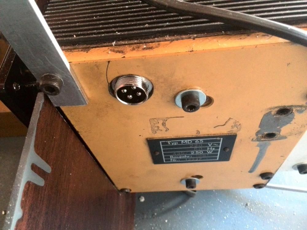
      P.S. Here's a picture from a Russian-language machinists forum, this user installed a "VEM 0,4 kW 1500 RPM, frame size 71" motor and a VFD, and used some kind of screw-on 4-pin socket to connect power to the lathe.

      post-100666-033336700 1423323125.jpg

      Advert
      #27135
      Gene Pavlovsky
      Participant
        @genepavlovsky
        #451793
        Steviegtr
        Participant
          @steviegtr

          1st of all that 4 pin plug is the sort of thing you fit to a microphone. Not suitable for 3 phase work. Ideally you would fit a 3 pin & E plug & skt like a reyrolle. Look under electrical supplies or ebay. Yoy can get one with threads on to lock it. They sell every kind of fitting you will need. Like a chassis mounted one. for the lathe end.

          One thing to note. I used to fit these in industry a lot of them including building panels to enclose them. The screen you talk about should only be connected at one end. So say at the VFD end you would connect your earth & screen together. At the motor end you would only connect your earth. The screen needs cutting back & either taping over or fit heat shrink. So basically the screen is earthed down to the mains , but remains open at the motor. That will stop RFI. I have done mine that way & have a DAB radio directly over the lathe & do not have any interference at any frequeny. I run mine in jog mode at 1.5 HZ so the chuck just creeps round which is great for marking out & any detail work you need to do. Also to see if the work is going to clear everything before speeding up. I make a bit of jewelry so it's ideal for me. Down at those low frequencies the drive has very little torque & you can stop the chuck by hand. I have a dedicated panel I built & will show the pics under here.

          The other thing I did & also glad I did was to fit a 10 turn speed potentiometer. I got a bit of a slating over it by some members. It was something we always did when building panels. The thing is it is only a lathe & I can understand why some say you do not need accurate speed control. That is true. But if you fit a single turn pot,, you actually only have 3/4 of a turn from off to max. That's the nature of a single turn pot. As an exercise the other day I tried to select various frequencies going up at 5hz a time & also trying to select a certain speed. I know again it is not essential. But if you said take the machine to 275rpm I can do this pretty quickly Also be careful of overdrive. The VFD I have can be set from 0 to 400 hz. I should imagine at 400 hz the rotor would explode. But I know I can safely go to 100hz.

          Because these motors we mostly fit are the 4 pole high torque version. If you fit a 2 pole version the motor standard would be 2800 rpm. But as we know a standard 4 pole motor on 50hz is 1400rpm. Some will argue but it can be slightly higher but never over 1470 ish.

          So as you can see if you ran your motor at 100 hz the speed will be around 2800 rpm. Which the motor & housing can cope with. But another thing to be wary of is that.

          Some lathe's & mine is such that it only has a plain phosphor bronze front bearing lubricated by an oil wick. Running at high rpm may not be a good idea. So far with all the materials I have cut I have not gone over around 900rpm. EDIT. Thinking about it you would really need a 4 pin & earth plug & skt because once the wiring leaves the VFD the earth & screen need to be separate. Some other safety features you can program into the inverter is things like e-stop. So set you machine to wind up to speed over a few seconds on start & on stop wind down in a few seconds. But when you hit e-stop it will stop imeddiately. Sorry for bad spelling. Hope all this helps. Any further info don't hesitate. You may get some varying answers to your thread. Another thing with an inverter is you can see the current being drawn at any set speed. 

          Steve.speed 2.jpgspeed.jpg

          Edited By Steviegtr on 11/02/2020 23:50:21

          #451808
          Robert Atkinson 2
          Participant
            @robertatkinson2

            100% second what @Steviegtr says. That metallic microphone connector is potentially lethal and is illegal to use on mains.. If you want something more compact than the "commando" type 3 Pin and earth connector suggested by steve, have a look at HAN connectors. Again you heed 3pin PLUS earth. This is subtly different from a 4 pin connector in that the earth contact is designed to make first and break last. This means if there is a fault and you are touching the motor as you unplug it to fault find the case cannot become live. The FEMALE goes on the FVD output , Male on the motor

            An example is **LINK**

            Other sources available

            Robert G8RPI.

            Edited By Robert Atkinson 2 on 12/02/2020 07:52:44

            #451811
            Ian Parkin
            Participant
              @ianparkin39383

              Whilst I quite agree that the plug and socket pictured gives me the willys they are fitted as standard to high frequency spindles used in woodworking routers and Cnc machines carrying 240v 3 phase up to 400 hz

              #451813
              Ian Parkin
              Participant
                @ianparkin39383

                What about these then Robert?

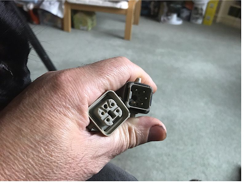
                widely used on German printing machinery for 415v3p

                ef642be2-91ee-4350-9440-85211821bdf2.jpegAre these illegal?

                #451818
                Ex contributor
                Participant
                  @mgnbuk

                  widely used on German printing machinery for 415v3p

                  Those and other variations of Harting connectors also widely used on machine tools for 3 phase connections – check the connector voltage rating to be sure (IIRC Harting are 600V).

                  Bear in mind that the cable screen also needs to be continuous through any connector, so 5 pins required (3 x phases, earth & screen) not 4.

                  It is always best to read the installation manual for the equipment you intend to use, as it is not unusual for VFD power cables to specify that the screen is connected at both the motor and drive ends.

                  I would avoid connectors if at all possible – you are adding a large number of additional connections, all of which are potential failure points. It is also possible that the VFD installation instructions will specify no cable breaks.

                  Nigel B

                  Edit for spelling !

                  Edited By mgnbuk on 12/02/2020 10:29:44

                  #451825
                  Pero
                  Participant
                    @pero

                    The question of earthing the screen has come up previously ( haven't most things? ) but, if I remember correctly, a definitive answer has not been reached – mainly as a result of different manufacturers having different recommendations – some at one end ( VFD ), some at the other ( motor ), and some at both.

                    It would be nice if someone with the right equipment could do a series of tests of each of the options and provide the results. The best solution could however vary depending on the VFD/motor combination and the physical arrangement of the parts and wiring. Not my field unfortunately but I would be interested in the results as I have a number of these units in store waiting to be installed.

                    Any volunteers?

                    Pero

                    #451826
                    Gene Pavlovsky
                    Participant
                      @genepavlovsky

                      Thanks for the responses guy. I am not thinking about using microphone connectors/cables for this application, even though I've done some searching regarding XLR connectors, and (e.g. using filters on mouser.com) they can be found rated for 250 V 16 A. I prefer to do a proper job, and use appropriate tools, connectors etc, if possible – especially if it can be a safety issue.

                      I'm in Luxembourg, and most commonly available obvious choice would be a IEC 60309 industrial plugs/sockets (known also as CEE and Commando – a particular brand name). I could probably buy the needed supplies in the local construction supermarket (Bauhaus, Hornbach). However, they are very bulky and their voltage/current ratings are quite an overkill for just powering a little <= 0.37 kW motor on a small lathe.

                      I have looked at CNC spindles, as was suggested, and found a lot of examples and pictures. If you just search eBay for 2.2 kW spindle, you will find lots of kits containing a 3-phase spindle motor and a VFD unit. Those spindles actually have connectors that look similar or exactly the same, as the one on the picture I posted. It looks somewhat similar, but I rather doubt it being a microphone connector. The connectors themselves are referred to as "aviation connector", searching for that term produces a lot of items from China (in sizes such as GX12, GX16, GX20, GX25, GX30 referring to the shell diameter or maybe outside thread diameter, in mm) – sold at a low price on eBay, AliExpress or Amazon, but I couldn't find actual standards for them, or why are they called aviation connectors. A Chinese company called RenhotecPRO at least has a datasheet, their GX20 connectors are rated at 400 V 10 A (4-pin) or 7 A (5-pin). If one is to believe these ratings, they seem to be fine for the application, and quite compact. With a metal body, can the screen be connected directly to the body (then a 4 pin connector would enough).

                      I still haven't chosen/bought a VFD unit, but I've already studied a few manuals. Looking at Yaskawa V1000 at the moment. Inverter Driver Supermarket has a quick-start guide for V1000, in that guide there is a 3-wire shielded cable, with 3 wires connected to the inverter's output on one side, and the motor's inputs on the other side, the cable's screen being connected to a ground strip near the VFD unit (also connected to the input power PE wire), and the motor ground (which has a separate "Earth" wire going to it). This corresponds to the wiring diagram in Yaskawa's own manual. So, either I follow these instructions, and use a separate earthing cable (with their own connectors, or maybe even ring terminals + bolts/nuts) – which would be a hassle to setup, or I have the ground wire in the same cable together with the three phase wires, utilizing the same 4-pin (5-pin was also suggested, I suppose for plastic-body connectors) connector?

                      The printing machinery connector looks small/convenient enough, where can those be found? I've searched for Harting, and they seem to have a lot of different connectors. It's really quite difficult to dig among the professional-level supplier such as mouser.com, there are just so many things available (and many of them quite expensive). I would really appreciate particular connector models (at least families), hopefully those that could be easily sourced and not too expensive.

                      #451827
                      David Jupp
                      Participant
                        @davidjupp51506

                        There is a difference between what is required for connector 'within' a machine, compared to those that provide a separable connection to the external supply. The provision or otherwise of separate earth bonding may influence what is acceptable.

                        #451828
                        Robert Atkinson 2
                        Participant
                          @robertatkinson2
                          Posted by Ian Parkin on 12/02/2020 09:03:25:

                          What about these then Robert?

                          widely used on German printing machinery for 415v3p

                          ef642be2-91ee-4350-9440-85211821bdf2.jpegAre these illegal?

                          Yes, they are safe and legal as long as they are the +E (earth type. That is the HAN connector I referred to in my previous post.

                          Robert G8RPI

                          #451829
                          Robert Atkinson 2
                          Participant
                            @robertatkinson2
                            Posted by Gene Pavlovsky on 12/02/2020 11:58:24:

                            <SNIP>

                            The printing machinery connector looks small/convenient enough, where can those be found? I've searched for Harting, and they seem to have a lot of different connectors. It's really quite difficult to dig among the professional-level supplier such as mouser.com, there are just so many things available (and many of them quite expensive). I would really appreciate particular connector models (at least families), hopefully those that could be easily sourced and not too expensive.

                            Search for HAN A 3 +E they are a Harting HAN series A 10A 3 pin plus earth. Commonly available from RS Components, Farnell etc. Both RS and Farnell will take personal credit card orders.

                            Robert G8RPI.

                            #451831
                            Ian Parkin
                            Participant
                              @ianparkin39383

                              Well those are harting brand and as you can see the earth doesn’t disconnect later than any other of the pins

                              #451832
                              Ex contributor
                              Participant
                                @mgnbuk

                                3 pole Harting set

                                Harting connectors can be a pain to specify, but they are made available as sets by some sellers like the Ebay listing above. Industrial stuff is never cheap, though !

                                Every VFD manufacturer has their own take on connecting up, so the manual for the particular drive you are using is the best guide. A quick look at several installation manuals / guides on RS Components website shows most are very similar in that screens are shown connected at both ends, though most suggest that having the earth within the cable is OK (one said to lay the earth seperately for preference & heavy duty installations, but within the cable was OK for low power & short runs). All showed a direct connection between motor & drive – no contactors or other breaks.

                                I would (if I really had to !) use a 5 pin connector & run the earth wire & screen through isolated pins (earth not connected to connector shell, but chassis socket casing earthed at panel). Reason being to ensure integrity of star point earthing, screen continuity & reduce risk of earth loops. Probably have to go to a 6 pin connector if using Harting to do this, as their earth pin is connected to the connector shell – this may well be an un-necessary complication, but I don't like earth wires to be connnecting at several points along their length.

                                But coming up with a solution that didn't require connectors would still be preferable IMO – my experience has been that such connectors contribute substantially to installation (un)reliability.

                                Nigel B

                                #451833
                                Robert Atkinson 2
                                Participant
                                  @robertatkinson2
                                  Posted by David Jupp on 12/02/2020 12:24:55:

                                  There is a difference between what is required for connector 'within' a machine, compared to those that provide a separable connection to the external supply. The provision or otherwise of separate earth bonding may influence what is acceptable.

                                  Correct, accessible connectors on voltages more than about 50V AC have to be "safe" which means earth making and breaking first (except for double insulated equipment) and touch proof power contacts on supply side. They also need to be correctly rated for voltage, current and environment. Typically this means a connector approved to some standard or another.

                                  Connectors that are only accessible with a tool or key only have to correctly rated. This is because it's assumed only trained persons will have access.

                                  Gene mentioned XLR connectors. while mains versions of these (mainly professional audio) connectors were (are?) available, they have not meet safety standards since the 1990's. This applies to many older designs like the "Bulgin" mains connectors. These can be used on existing equipment (or internally) but should not be used on new equipment and should be replaced with modern types if damaged.

                                  Robert G8RPI.

                                  #451836
                                  Robert Atkinson 2
                                  Participant
                                    @robertatkinson2
                                    Posted by Ian Parkin on 12/02/2020 12:43:20:

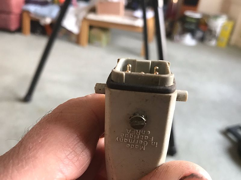
                                    Well those are harting brand and as you can see the earth doesn’t disconnect later than any other of the pins

                                    Yes that one pictured does.

                                    The 5th pin at the top is longer than the others.

                                    Not ALL HAN connectors do, They have to be nPin + PE or similar description to be safe for external mains power connectors.

                                    Robert G8RPI

                                    Edited By Robert Atkinson 2 on 12/02/2020 12:55:56

                                    #451837
                                    Gene Pavlovsky
                                    Participant
                                      @genepavlovsky

                                      Ok, I found those Harting connectors as HAN 3A (3-pin +Earth), or HAN 4A (4-pin +Earth). They seem to be very modular: separate housings, plastic inserts (male or female) for particular number of contacts, crimp contacts for which a Harting crimp tool is needed, etc. I've looked at the prices on Farnell, and they are quite expensive! A single connector (as kit) is 30-40 GBP. The crimper is over 150 GBP. Probably one could get by using a regular crimper and/or soldering, but that's not proper, doesn't make sense to pay a lot for nice connectors and then do a half-ass job.

                                      I'm leaning towards trying out these GX20 connectors. Still trying to figure out whether I'd need a 4-pin or 5-pin (5th pin for connecting to the screen, but maybe it could just be terminated to the connector housings?)

                                      #451838
                                      Gene Pavlovsky
                                      Participant
                                        @genepavlovsky

                                        Just saw the several other posts made since I last reloaded the page!

                                        Thanks for the link Nigel, that confirms what I found. Very expensive! And that kit doesn't include the crimp contacts (terminals), I'm not mentioning the crimp tool either..

                                        I will have a short run and rather low power application. I can't seem to think of a convenient solution without using connectors. If I have the VFD permanently wired to the motor, it will be very tricky (for 1 person) to move both the 45 kg lathe and the VFD enclosure from their 2 different shelves, at the same time. Unless I make the power cable rather long, in which case I could bring the VFD box to the workbench first, then the lathe. Sounds like a pain in the ass, but maybe not as much as I think? But then what to do with the 2-3 m long power cable sitting on the bench, while the lathe is right next to VFD. It might get in the way, or cause more EMI?

                                        #451839
                                        Gene Pavlovsky
                                        Participant
                                          @genepavlovsky

                                          I would not be concerned with whether the earth pin would make first and break last, or at the same time as other pins – because I would only be connecting/disconnecting the power cable when the inverter is unplugged from the mains.

                                          #451845
                                          Ian Parkin
                                          Participant
                                            @ianparkin39383

                                            This one and all the others on the machine that these came off are all the same

                                            8348889b-e75f-4e9d-a7cb-0904f8c3d0f2.jpeg

                                            #451847
                                            Ex contributor
                                            Participant
                                              @mgnbuk

                                              And that kit doesn't include the crimp contacts (terminals), I'm not mentioning the crimp tool either.

                                              Harting inserts are also available with screw clamp inserts – I have yet to install a crimp terminal type. In any case, the "crimp" terminals can also be soldered.

                                              WRT to power contacts breaking before the earth pin when disconnecting under power, Harting state :

                                              Warning

                                              • These connectors should not be mated or unmated under electrical load.

                                              Lifting 45kg on to a shelf ? More than double the recommended limit for safe lifting to elbow height !

                                              Nigel B.

                                              #451848
                                              Gene Pavlovsky
                                              Participant
                                                @genepavlovsky

                                                Nigel, you're right, but I'm not lifting it from the floor, it's from a bench to a shelf (more or less same height). The lathe is screwed to a wooden board so it's not difficult to grab it.

                                                Even though I haven't gone to a gym since about a year ago, I am still in good enough shape to handle this baby

                                                So, do you recommend a long permanently wired cable?

                                                #451855
                                                Ex contributor
                                                Participant
                                                  @mgnbuk

                                                  How about doing the connector bit the other way round – mount a chassis plug onto the motor connecting box and a cable mount socket on a flying lead from the drive box ?

                                                  These connectors

                                                  seem to be rated OK (400V 5A) & have a chassis plug & cable mount socket. They also appear to meet cost criteria. Note that the exposed pins in the chassis plug are on the motor, not the cable, so no shock risk when disconnected.

                                                  Your drive mounting box would have the motor cable permenantly attached, rather than the cable being attached to the motor/lathe, but shouldn't be an issue ?

                                                  Personally though, I feel a permenantly wired cable would be the way to go wink

                                                  Nigel B

                                                  #451879
                                                  old mart
                                                  Participant
                                                    @oldmart

                                                    As long as you always remember to do things in the correct order.

                                                    1. Connect the vfd to the motor.

                                                    2. Connect the vfd to the mains and switch on. Run the motor.

                                                    3. Power down the motor using the vfd controls.

                                                    4. Turn off the mains.

                                                    5. Disconnect the vfd from the motor.

                                                    If you do this every time no harm will be done.

                                                    #451886
                                                    Robert Atkinson 2
                                                    Participant
                                                      @robertatkinson2
                                                      Posted by Ian Parkin on 12/02/2020 13:19:42:

                                                      This one and all the others on the machine that these came off are all the same

                                                      8348889b-e75f-4e9d-a7cb-0904f8c3d0f2.jpeg

                                                      As I said, not all HAN connetors are suitable, only the ones listed as having a protective earth connection. The first picture did look like it had a longer pin (actually placed firther forward, the actual pin is the same.

                                                      As has been noted they come with crimp or screw contacts. If using a screen you ideally need a metal shell version and cable clamp designed for screened cable. You could terminate the screen to a wire and use 4+PE connector.

                                                    Viewing 25 posts - 1 through 25 (of 38 total)
                                                    • Please log in to reply to this topic. Registering is free and easy using the links on the menu at the top of this page.

                                                    Advert

                                                    Latest Replies

                                                    Home Forums General Questions Topics

                                                    Viewing 25 topics - 1 through 25 (of 25 total)
                                                    Viewing 25 topics - 1 through 25 (of 25 total)

                                                    View full reply list.

                                                    Advert

                                                    Newsletter Sign-up