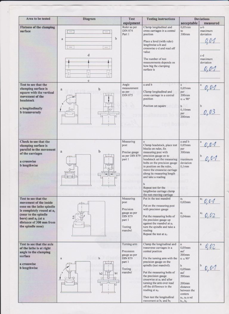
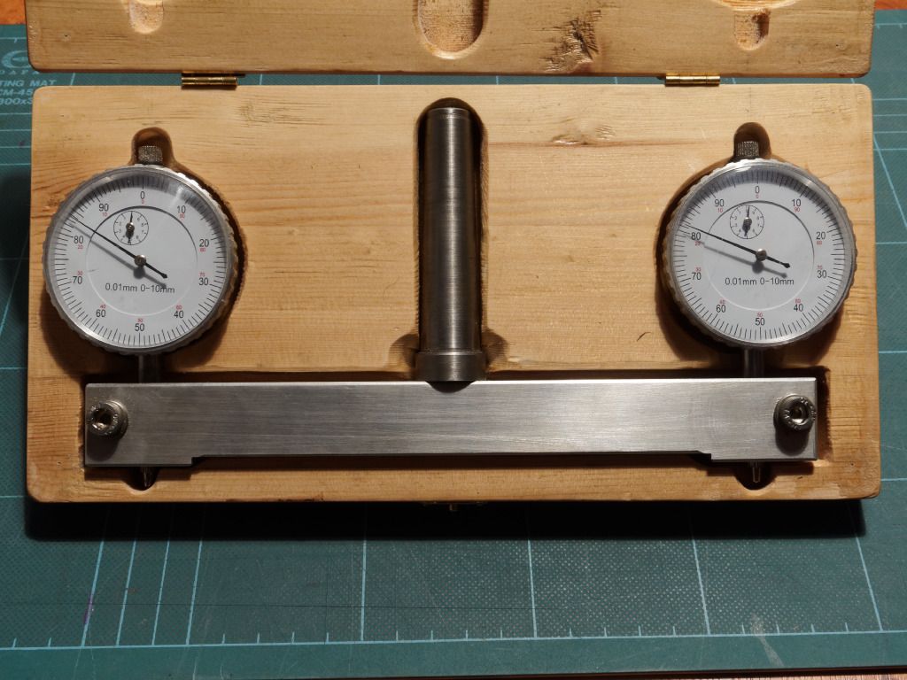
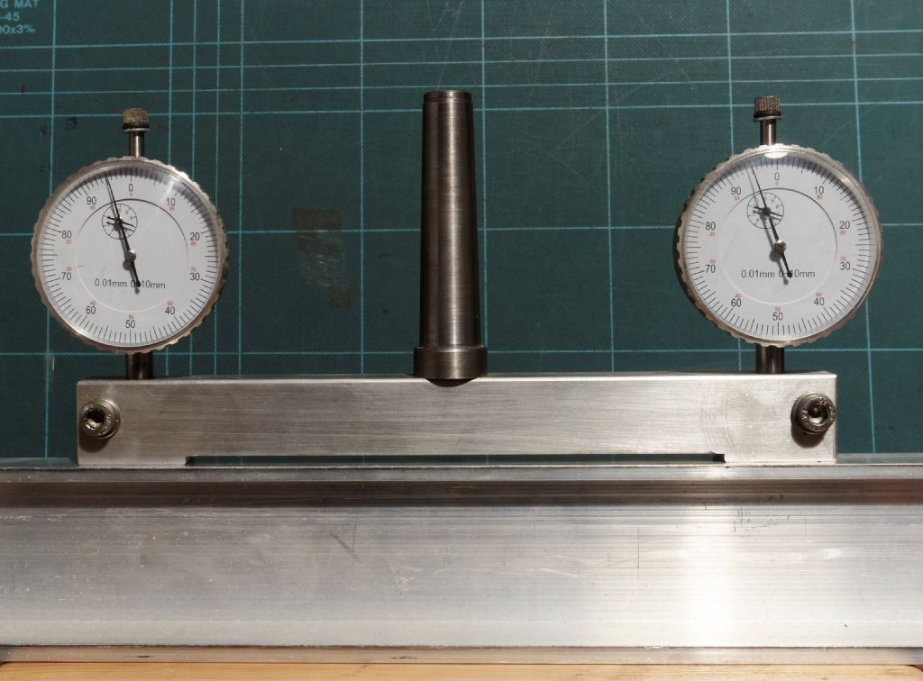
Not wishing to hijack Edward Crouch's tramming thread so I've I've opened a related question. I've just re-trammed my WM18 after a dig in turned the head slightly. The mill is fitted with a stop screw to facilitate re-alignment but I don't entirely trust it.
As usual I've done the job by guessing the procedure. This isn't clever given that I could easily have asked on here first!
My first attempt to measure unwanted tilt involved using a DTI in a collet and a set-square bolted to the table. It was immediately obvious that this method is badly flawed.
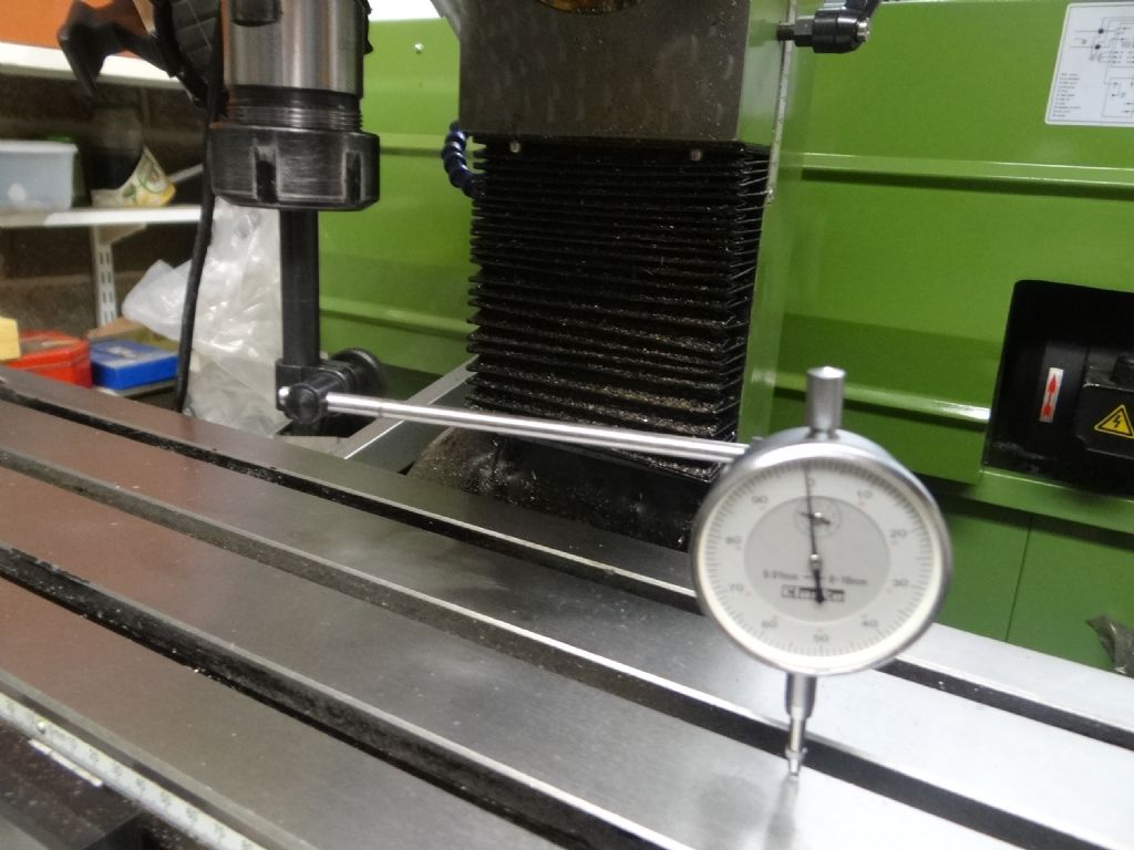
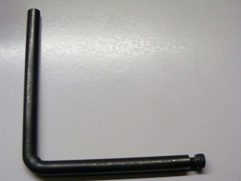
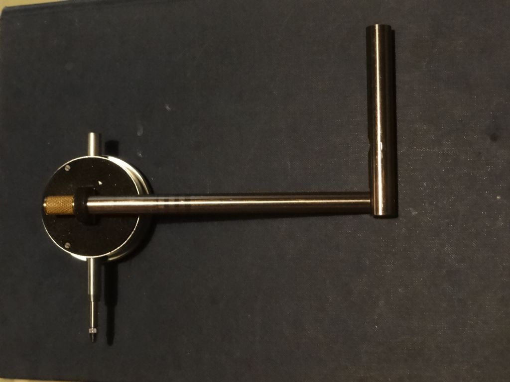
My second attempt used the set-up shown in the photo. A DTI is mounted at right angles to a collet mounted rod in the spindle such that the DTI point touches the table about 160mm away from the spindle axis.

To check right/left tilt I turned the spindle until the DTI is due east (assuming the pillar to be north). In that position the DTI was lowered to touch the table plus one dial revolution to zero the meter and show any ± movement.
Then I rotated the spindle through 180° so that the DTI was in the due west position and noted the measurement. (The point of the DTI was lifted carefully over the slots.)
On my mill due west measured 0.22mm lower than due east, the two points being 320mm apart. After about 40 minutes spanner work, tapping with a rubber mallet, and many, many expletives, I managed to reduce this to a DTI needle thickness zero.
There are a number of ways I feel this method could mislead, for example the joints of DTI assembly shifting as the spindle is turned, spindle run-out, a bad collet, loose gibs, or the DTI sticking. Am I measuring tilt the right way, and what would the team advise?
Thanks,
Dave
Edited By SillyOldDuffer on 29/01/2017 14:20:24
Edited By SillyOldDuffer on 29/01/2017 14:20:47
SillyOldDuffer.


