Tracing an electrical fault

Advert

Tracing an electrical fault

Home Forums General Questions Tracing an electrical fault

Viewing 6 posts - 26 through 31 (of 31 total)
  • Author
    Posts
  • #321334
    Clive Hartland
    Participant
      @clivehartland94829

      This is just a thought, maybe the wiring is not compatable with the requirements of the loads applied. I would consider a complete rewire with good size cable and water proof enclosures, new switches etc.. Peace of mind as a hot part of a circuit on a boat is a danger and fire afloat is not good. Permanent connections to equipment to eliminate bad joins, plugs and sockets etc.

      Just a thought.

      Clive

      Advert
      #321348
      SteveW
      Participant
        @stevew54046

        I would second the idea of a dedicated battery for anything critical. Short leads, few connections, wiring easy to check or replace, just one switch. Fewer components = more reliable.

        Steve

        #321363
        Sam Longley 1
        Participant
          @samlongley1
          Posted by SteveW on 13/10/2017 18:55:11:

          I would second the idea of a dedicated battery for anything critical. Short leads, few connections, wiring easy to check or replace, just one switch. Fewer components = more reliable.

          Steve

          I have a pair of AGM domestic batteries 800mm from the electric cupboard with a red flash starter battery.

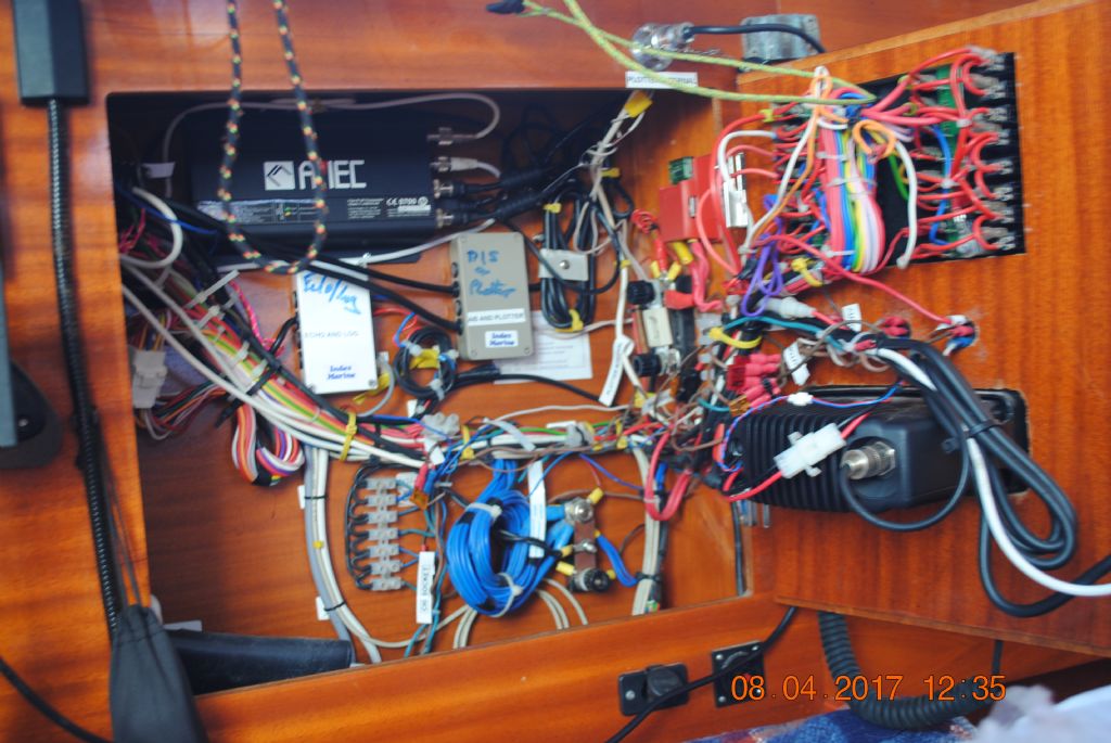
          the AGM's normally sit between 12.8 & 13 V in operation & 14.4V when under charge. I do not believe that they are faulty as they are fairly new & hold the charges for weeks in the winter without topping up the charge. This is the cupboard from where the autopilot wiring starts it then goes down behind ducts & panels to the stern of the boat via a tortuous route !! 90% of the wiring is manufacturer installed– without any wiring diagrams I might add. I have only installed the AIS, & renewed the compass,  Echo sounder & log & supply to autopilot & log – that is why they kick off from junction boxes & a plotter reserve plug- top right in picture


          electric box


          Edited By Sam Longley 1 on 13/10/2017 20:51:07

          Edited By Sam Longley 1 on 13/10/2017 20:55:09

          #321367
          Dod Mole
          Participant
            @georgeclarihew

            There is enough good advice on equipment needed and what to look for.

            May be a bit late but using the half and half tracing method often speeds isolating the faulty half of the circuit then halfway up or back the dead part and so on in ever decreasing halves till – — — — – BINGO !! smiley

            Edited By George Clarihew on 13/10/2017 21:20:56

            #321378
            Mike Poole
            Participant
              @mikepoole82104

              Sam, your photo illustrates exactly why you need to know your enemy before you embark on a fault finding process, most of that wiring will not be involved in the relevant circuit but you need to know what is. As George mentions the half split method is a sound fault finding process but it is essential to know the circuit completely or how do you pick a midpoint? and make meaningful tests.

              Mike

              #321434
              Phil Whitley
              Participant
                @philwhitley94135
                Posted by John Haine on 13/10/2017 09:23:46:

                Posted by Phil Whitley on 12/10/2017 21:53:45:

                Get yourself an old fashioned DC buzzer or doorbell. the type that uses a vibrating arm and a pair of contacts. This is so it will draw a reasonable amount of current, as if you use an electronic one, it will not draw sufficient current to make the fault occur. attach the bell/buzzer to the supply for each instrument in turn, then go through the circuit working your way back towards the batteries till you hear the bell/buzzer falter or stop. You have found the fault. be especially suspicious of fuse boards or breaker panels.

                I think that this might be a bit dodgy with modern electronics as bells/buzzers can create high voltage spikes as the contacts break which can get through to the terminals if the contacts arc. This could damage the equipment. An equivalent but safer alternative is to use the meter to measure volts, with a shunt resistor of say 100 ohms to draw current, then look at the volts at the power input to each device whilst wiggling wires. And as someone else said, gather as much evidence as you can of what exactly happens. My experience of fault finding is that I spend most of the time staring into empty space forming theories of what the trouble could be and experiments to test them, but little time actually measuring or testing.

                I would expect the OP to have the equipment disconnected before he connected the bell/buzzer!!

              Viewing 6 posts - 26 through 31 (of 31 total)
              • Please log in to reply to this topic. Registering is free and easy using the links on the menu at the top of this page.

              Advert

              Latest Replies

              Home Forums General Questions Topics

              Viewing 25 topics - 1 through 25 (of 25 total)
              Viewing 25 topics - 1 through 25 (of 25 total)

              View full reply list.

              Advert

              Newsletter Sign-up