Tom Senior M1 Vertical Head unit

Advert

Tom Senior M1 Vertical Head unit

Home Forums Beginners questions Tom Senior M1 Vertical Head unit

Viewing 8 posts - 26 through 33 (of 33 total)
  • Author
    Posts
  • #93969
    Brian Davies
    Participant
      @briandavies19472

      Hi Tony, I've turned up the invoice and the bearings numbers are as follows:

      1 off A/C LJT1 type ALS8 £46.99

      1 off A/C MJT7 Type AMS7 £35.58

      2 off Thrust races: FT7/8 £10.22 each

      All the above plus VAT

      Hope this helps

      Regards

      Brian

      Advert
      #93975
      Steve Garnett
      Participant
        @stevegarnett62550
        Posted by Brian Davies on 09/07/2012 08:22:04:

        Hi Tony, the thrust races are in fact identical, I replaced these and found no necessity to adjust with shims.

        The flat thrust races on the primary drive shaft are identical, but the ball thrust races on the vertical shaft (which Tony was talking about) aren't. These are the original bearing specs:

        Top Bearing: Hoffman MS9ACD. Inside diameter 7/8", overall thickness 0.6875"

        Bottom Bearing: Hoffman LS10ACD. Inside diameter 1", overall thickness 0.623"

        The OD of both bearings is 2 1/4" The MS9 and LS10 bearing specs are standard – there should be a lot of places you can get these from without paying Redhill's prices…

        Edited By Steve Garnett on 09/07/2012 10:56:16

        #94000
        geoff taylor
        Participant
          @geofftaylor25177

          Tony, I purchased my output spindle bearings from "the bearing company"

          They are the LJT1 and MJT7/8 (AMS7 / ALS8) as mentioned above, slightly cheaper at £29 and £33.30 respectively + VAT, they supplied genuine RHP bearings, which fitted and work a charm.

          The top bearing inner is also very very tight on the shaft, you'll need a very sturdy puller or at least I did.

          I also had to make up some cups and draw bolt to pull the bearings back in properly and not thumping things together. Somewhere I have a very good account of the job, not sure what forum I got it from but it is really good, as it involved the use of the wifes oven and freezer to make reassemby just that little bit easier.

          Head runs a dream now and not like a coffee grinder.

          Good luck – Geoff

          #119559
          wendy jackson
          Participant
            @wendyjackson

            hi chaps.i have a few teeth missing on the gear inside the head.question is this gear part of the shaft . would i be able to just remove one bearing and knock the shalt out. and can i have more setails of what pullers you used.thanks michael

            #119566
            wendy jackson
            Participant
              @wendyjackson

              hi chaps.i have a few teeth missing on the gear inside the head.question is this gear part of the shaft . would i be able to just remove one bearing and knock the shalt out. and can i have more setails of what pullers you used.thanks michael

              #139797
              Graham Wharton
              Participant
                @grahamwharton

                Hello all, Sorry to resurrect an old thread, but I'm still utterly confused by the bearing arrangement in the knucklehead ad how to apply the correct preload.
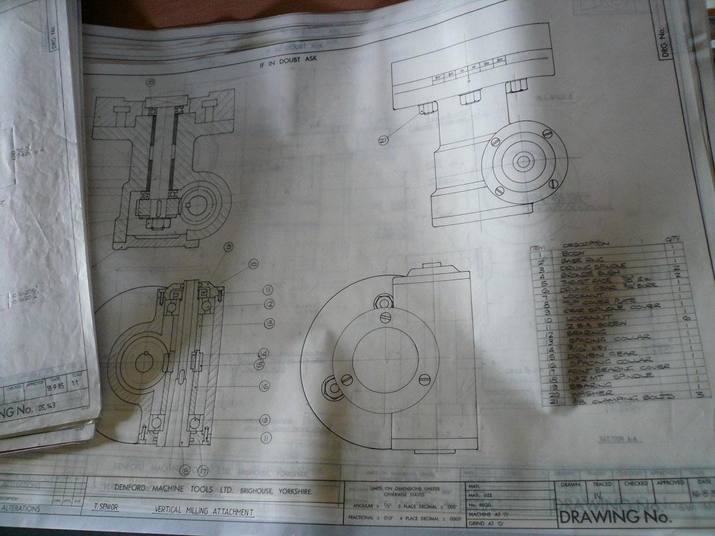
                Looking at the drawing in the bottom left, it would appear that (with no shoulder for the outer shells to push against) the nut on the spindle only serves to clamp the bearing inner shells, spacing collars and driving nut against each other. This does not provide any preload adjustment, infact it could serve the opposite by unloading the angular contact preload when tightened up depending on the outer shell positions.

                One way of setting preload could be the action of the end caps pushing in on the outer races of the bearings through the use of some spacers, but this doesn't feel right.

                another method of applying preload could be to make sure the bearing outer shells butt up against the end caps then shimming the inner spacing collars until the right preload is achieved.

                Both of the above methods require using the end caps as the immovable object for the preload to act against which doesn't feel right due to their small retaining screws.

                Do angular contact bearings work with no, or negative preload?

                If you just assemble the spindle by pulling/pushing in the bearings and shaft, then tighten the retaining screw, and actually manage to gain some preload through the action of pressing in the outer shells so they are tight, then over time with the vibrations of cutting, wont the outer bearing shells relax and any preload you did have, would disappear.

                I'm totally confused. I think the spindle guy must have been on annual leave when they came up with this design.

                Any more thoughts?

                #139820
                Graham Wharton
                Participant
                  @grahamwharton

                  I was thinking about this last night whilst laid in bed (as you do) and Ive come to the conclusion that I am going to attempt Steve Garnetts proposed modification by fitting a correctly sized sleeve to the inside of the casting. It will be machined to the correct length so that the end caps securley hold the bearings in place against the sleeve and this will form the rigid outer portion of the spindle. The angular contact bearings will be turned upside down so the angle of contact is in the correct direction to act against the outer sleeve, and the top section of the inner spindle sleeve will be removed. I intend to leave in the lower inner sleave portion between the driving cog and the bottom bearing, as this sets the height of the cog, and then just place a small locking ring, held in place with a grub screw above the cog (with an appropriate flat machined onto the shaft to prevent shaft nerfing). All driving force exerted onto the cog from the driving shaft will be in the downwards direction so that should work just fine. I may have to slacken the fit of the bearings on the very end of the shaft to allow the top bearing to move on the shaft as prelaod is adjusted (I seem to remember it required the press to get the bearing to move on the shaft right till the end. Preload will then be adjusted using the nut, as I am sure it was designed to be done in the first place.

                  This should give the entire spindle some rigidity and allows the angular contact bearings to operate under the right level of preload. However this still means that the entire spindle assembly is only held in the main casing by the retaining force of the bearing fits, and the end caps, but should hopefully be strong enough for the milling forces seen on what is a reasonably small head.

                  I should add that this is the knucklehead for the Tom Senior Junior which is slightly smaller than the M1 knucklehead, but the design is mostly the same.

                  I will keep you updated on how I get on.

                  Graham

                  #141875
                  Graham Wharton
                  Participant
                    @grahamwharton

                    Hi, just wanted to update you chaps on how I got on with Steve Garnetts proposed modification by using a sleeve inside the vertical head.

                    Unfortunately this has not worked. If I had made some measurements in the first place, I could have saved myself a days worth of machining, as I only found out it wouldn't work at the last minute after doing most of the machining on the sleeve. On the vertical column on the Junior, the diameter of the bevel gear on the drive shaft is very close to the internal diameter of the column. This means there is no clearance around the gear to fit a sleeve that runs all the way through the column.

                    So, I am now considering grooving the bore of the column about 1 inch down from the top and one inch up from the bottom to fit internal circlips. To allow the positioning of the groove to be non accurate, they would be positioned slightly below the top bearing and above the bottom bearing, and a nicely fitting sleeve turned up to act as a spacer between the circlip and the bearing face (easier to change the length of the sleeve to get the bearing in the right place, than move the groove! ). The bearings would push against the circlips, as they would in a normal head with machined shoulders.

                    So, that now raises a question about circlips, given I would have the whole shaft preload acting against two circlips, and infact there would also be milling forces acting against the circlip via the angular contact bearing, am I likely to see failures of the circlips, or their grooves in this scenareo. Having just written all this, I am beginning to think that this is not the best of ideas now.

                  Viewing 8 posts - 26 through 33 (of 33 total)
                  • Please log in to reply to this topic. Registering is free and easy using the links on the menu at the top of this page.

                  Advert

                  Latest Replies

                  Home Forums Beginners questions Topics

                  Viewing 25 topics - 1 through 25 (of 25 total)
                  Viewing 25 topics - 1 through 25 (of 25 total)

                  View full reply list.

                  Advert

                  Newsletter Sign-up