Thread major diameter

Advert

Thread major diameter

Home Forums Beginners questions Thread major diameter

Viewing 19 posts - 1 through 19 (of 19 total)
  • Author
    Posts
  • #230499
    Mike Rolly
    Participant
      @mikerolly

      Hello all,

      I am wondering on how best to go about cutting a thread to dimensions in the thread tables is achieved.

      Example: I wish to cut an external thread on a round of 4140 annealed steel.

      The thread is 5/TH " x 24 TPI 60 degree UNEF Class 3A. Max major diameter is listed as .6250", the minor, .6178". No allowance given due to thread tolerances. With pitch. major listed as .5979" and minor as .5949". UNR minor diameter is .5754" for the external thread.

      OK, all looks good on paper and I apply (attempt to) the necessary cuts to get my diameter to .6250", my major diameter. It's from here I have problems. I set my compound to the required 29.5 degrees and use a hand honed 6mm HSS toolbit with the 60 degree angle ground and it at the work piece on centre and perpendicular to the work piece.

      Using the correct gearbox ratios I cut my thread with a dial indicator against the face of the toolpost to dial my thread depth in, then checked with 3 wires.

      This is when I invariably end up with dimensions different to the listed table values, my pitch major diameter is always larger than the listed .5979" although I mange to hit the minor pitch diameter either dead on or within a thou or two.

      I am baffled, my thread does not look like a UNEF thread form, my threads are more pointed than the UNEF thread that have a round crest.

      What am I doing incorrectly here gents ? Do I need to run a flat file over my major pitch threads to round the crests and decreases size? I cannot see that being conducive to accuracy through. I have looked at purchasing a set of thread files to see if I can correct this diameter issue.

      Although, I maybe doing something wrong in my execution, hence my request for assistance.

      Thanks,

      Mike

      Advert
      #8058
      Mike Rolly
      Participant
        @mikerolly
        #230515
        Chris Evans 6
        Participant
          @chrisevans6

          You are doing nothing wrong. It is just the way single point threading works out. You need a shadowgraph to get the point radius/flat correct and being single point you will never crest the major diameter. Go with your file over or buy a full form insert and holder.

          #230517
          JasonB
          Moderator
            @jasonb
            Posted by Michael Rowlingson on 17/03/2016 22:57:27:


            I am baffled, my thread does not look like a UNEF thread form, my threads are more pointed than the UNEF thread that have a round crest.

            Mike

            I thought UNEF had flat crests and rounded vallys to the male thread , at least thats whats in my Machinery's Handbook and it also gives details of the different tollerences.

            If you measure OK with the 3 wires and your minor dia is OK then you may just need to faltten the tops to get down to your Major dia

            Edited By JasonB on 18/03/2016 08:24:47

            #230520
            Kettrinboy
            Participant
              @kettrinboy

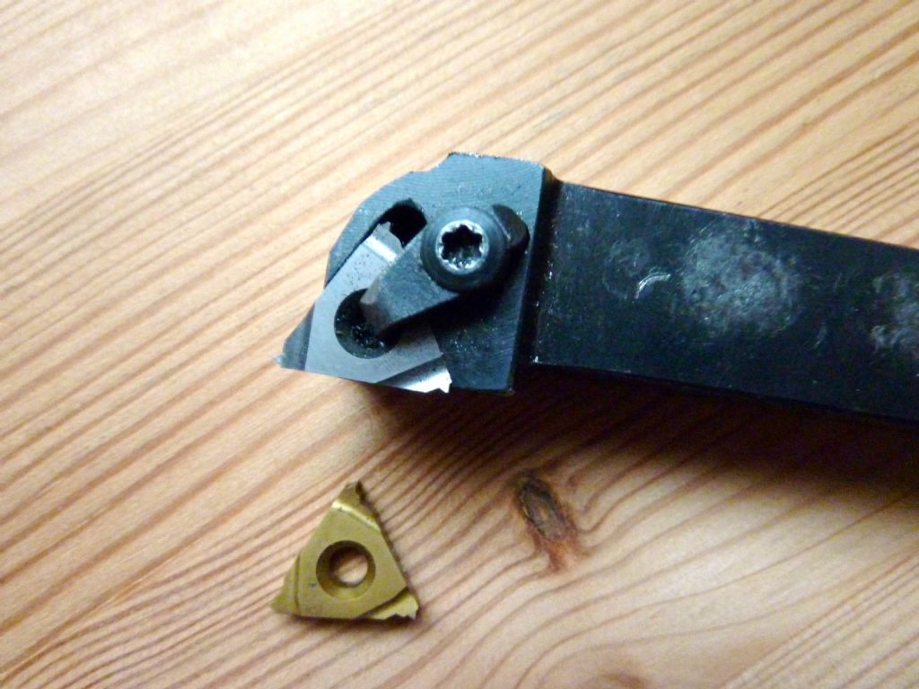
              As said a full form insert as shown in the pic is the best way to get an accurate form , no need to set the compound rest over but just align one edge of the insert with say the chuck face and then cut until the thread outside dia is dead on and then from there its only a few thou to get to a 3A limit , at work we used thread parallels and ring gauges to check final size. but in the absence of these measuring the od of the thread works well.enough.

              regards Geoffsnaptap.jpg

              #230530
              Mike Rolly
              Participant
                @mikerolly

                Thank you for the information regarding full form inserts, this is the first I have heard of them. Sure enough they are the answer to my threading form, excellent inserts to have in the UNEF pitches I am working with.

                Thanks for showing me these gents,

                Mike

                #230531
                KWIL
                Participant
                  @kwil

                  Since we do not know what power the OP's machine has, the 1/2 angle setover approach is to be recommended in most instances.

                  #230536
                  Ajohnw
                  Participant
                    @ajohnw51620

                    Setting the compound over reduces the cutting forces a lot and can lead to a better finish.

                    Maybe the problem is down to not doing this the classic way. The first 2 calculations are done to allow the use of a simple pointed tool

                    Recalc the outside diameter to remove any rads used on the crests – more on that later.

                    Recalc the depth that has to be cut to get the flanks correct with a simple pointed tool – this involves cutting deeper to remove any flat or rad in the valleys

                    Recalc the depth of cut in terms of the feed angle the compound slide is set at.

                    Cut the thread with the cross slide set to zero and the cut applied with the compound slide. That way the cross slide can be used to withdraw the tool and reposition it for each cut.

                    I wouldn't use a dti. They are comparators really not linear measuring devices.

                    Having done this there can still be problems especially with the outside diameter as in practice threads with flat topped crests will have a slight rad on the corners so either, relieve with a file, turn down until a gauge fits or allow for this on the outside diameter. Something of the order of 0.005" radially on a 5/8" dia thread should clear them and wont weaken the the thread significantly. The use of a pointed tool ensures the roots clear.

                    When you measure with a wire use the mean diameter method – the wire some way down into the threads. That checks the flank positions which is the important aspect. Some tables give this dia but it can be calc'd for any suitable wire diameter.

                    I sometimes set at near 30 degrees for this type of thread however on a 5/8" dia one i would probably set at 30 degrees and take the last couple of thou off with the cross slide until the wire reading was correct. Just add that I would ideally want a go no go guage to check as more may need taking of the outside diameter.

                    John


                    Edited By Ajohnw on 18/03/2016 10:05:14

                    Edited By Ajohnw on 18/03/2016 10:06:15

                    #230618
                    Mike Rolly
                    Participant
                      @mikerolly

                      Thanks again for the information, I priced up full form inserts in 24, 28 and 32 TPI this afternoon and received some sticker shock. I would probably be in for three new threading bars to hold the inserts in a tool holder on my BXA sized QCTP on my Colchester Master as well. FYI the master is running a 3hp, 3 phase motor controlled with a VFD.

                      I understand your explanation John and it makes sense with the added advantage of not buying new tooling at this stage. I do have ring gages in 24,28 and 32 TPI for the corresponding TPI for UNEF threads. I agree with the unsuitability of using a DTI for measuring, I do use a DI in a mag base for this duty.

                      I recall seeing a bloke showing me his thread cutting method some time ago. I doubt if I have the technique remembered correctly though. If my memory serves; it was based on using the crosslide to feed in on the thread, however I remember he still was using the Top slide? The thing that sticks in my mind was the cross slide movement along the Z axis. He was alternating between a feed of approx 2 thou in the +Z and then adjusting for backlash, feeding the slide 2 or so thou in the -Z . I remember thinking tat it seemed like a fair bit of mucking about with the cross slide and never tried it myself.

                      I do wonder though if there maybe some merit in this technique ? I imagine I have not remembered the sequence of ops correctly yet I imagine some one may have heard of a method that sounds vaguely familiar to this.

                      My thinking is maybe he is starting his threads on the Major pitch diameter and cleverly manipulating the cross slide in a way that gave him UNEF threads?

                      Thanks,

                      Mike

                      #230624
                      Ajohnw
                      Participant
                        @ajohnw51620

                        The way that some one showed you is probably the one I mentioned.

                        Set the compound slide to the flank angle.

                        When the tool is positioned for the first cut the compound and cross slide dial will be set at zero.

                        Apply a cut with the compound

                        When the cut is complete wind the tool out with the cross slide and back to the start

                        Reset the cross slide to zero and apply the next cut with the compound

                        and so on until it's cut.

                        Maybe a bit more later as I have something I must do.

                        John

                        #230635
                        Ajohnw
                        Participant
                          @ajohnw51620

                          The next thing is the outside diameter of the bar you are going to thread. I've seen comments that it should be 98% of the full thread diameter which on a 5/8 diameter thread means 12 1/2 thou under size. Sounds reasonable at 5/8 dia but I would wonder about the % at small diameters. Some thread table may put a limit on the size of the rad that might be there where the usual information suggests that the corner is square. Rather than turning the bar to 0.613 dia it wouldn't matter really if you turned to 0.610. That aspect has to be accounted for when working out the depth of cut what ever the od is.

                          Some tables will give enough information to work out the depth of cut assuming a pointed tool rather than a form tool. That then needs to be converted to a figure that accounts for the tool being fed in at 30 degrees rather than straight in. I had a quick look for a web page that explained how to do that but no luck. Dial indicators are not meant to measure distance really so it's safer to use the dials on the machine slides which are.

                          When the thread is checked with wires it's to ensure that the flanks are in the correct place. One way might use specific diameter wires that could result in measurement being exactly the same as the theoretical diameter of the actual thread but it needs a lot of different sized wires. The other way is to use wires that go well into the thread and calculate what the measurement over them should be – I couldn't find the sums for these on the web either.

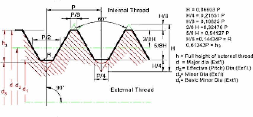
                          The type of thread chart you need to find is one like this which is for metric threads

                          metricthreads.jpg

                          The only problem with that is the likely hood of having small rads on the sharp corners shown at the crests. Whitworth bless him realised that sharp corners are not a good idea on cutting tools because they are hard to make and maintain. Seems Europe and the USA didn't.

                          There will also be a table like this for internal threads.

                          To be honest when I have needed to cut precise close fitting threads at home I have always done the sums and then fitted it to the part they go into rather than use wires. If done that way there is a need to be well aware that there may be rads where charts show none otherwise the thread will work loose pretty quickly if used much as the sharp corners will wear off.

                          Maybe some one else knows of a web pages that goes through the various sums. There should be one as it is a standard thing to see in text books where turning may be part of a course.

                          John

                          #230652
                          Clive Foster
                          Participant
                            @clivefoster55965

                            By far the easiset way to keep track of thread depths is to use what I was taught as the zero-to-zero method. Most especially if you may need to make corrections for a threading tool that is not to true full form shape. In the home shop tools are almost invariably too sharp on the point so you need to cut a bit deeper. Geo. H Thomas describes the zero-to-zero method in Model Engineers Workshop Manual, although not under that name, attributing it to a star turner and considers it good which is reccommendation enough for me.

                            The two great advantages are:-

                            1) the topslide only needs to be set to approximately the thread half angle, my topslide lives at 25° off pretty much premanently to keep the handles out of each others way and this works fine for both 55° and 60° threading.

                            2) you set things up before you start to finish with both cross and topslide on zero so the lathe does all the infeed calculations for you.

                            Assuming the job has been turned to the correct diameter method is :-

                            1) Set topslide over to a bit less than the thread half angle

                            2) Mount tool perpendicular to job

                            3) Bring tool tip up to touch the work

                            4) Set both top and cross slide dials to zero

                            5) Back off the cross-slide a little so the tip doesn't scratch the job and move saddle to take tool clear of the end of the workpiece

                            6) Feed the cross-slide forwards past zero by the desired thread depth

                            7) Set the cross-slide dail back to zero

                            8) Pull the topslide back far enough to clear the work the feed forward enough to make the first cut at whatever depth seems right to you

                            9) Make a threading pass

                            10) Pull back the cross-slide to clear the job and return to the starting point

                            11) Apply feed for the next cut via the topside, set the cross-slide to zero and make the next threading cut

                            12) Repeat steps 10 and 11 until both dials are at zero.

                            If the thread size is wrong adjust the setting on the cross-slide for successive passes until things are correct. Don't touch the top slide when correcting. Generally you will need to go deeper as home ground tools are usually too pointed. Once you have the thread size right re-set the cross-slide to zero and any further threads will come out right. If youa re only doing one thread which needs to be perfect best to do a test piece first and note the correct infeed for your tool.

                            A threading stop on the cross-slide makes for faster work as you dont have to read the dial when re-setting for the next threading pass.

                            I like the Johansson / SKF two thread full form chaser system. The 'bite out of a circle" form tools will stand several lifetimes worth of sharpening at my rate of use. Cant beat a coventry die head for small work.

                            Its not too hard to calculate the extra feed needed for a sharp pointed tool. Easiest way to get approximately the right, albeit flat, tip width is to make the tool sharp, measure its length and trim the end back enough to truncate the tip to give a suitable flat. Measure how much shorter you have made the tool then reduce the calculated sharp point infeed by the same amount. This is a bit wasteful on tool steel because you have to go back to sharp each time then trim back. Helps if you have a holder for short bits and have two or three tools on the go with different tip widths.

                            Clive.

                            Edited By Clive Foster on 18/03/2016 21:52:02

                            Edited By Clive Foster on 18/03/2016 21:53:25

                            #230653
                            Trev67
                            Participant
                              @trev67

                              Hi Mike

                              I'm not an expert on screwcutting, but I have done a bit. This post got me thinking, so I looked on the web for some reference to the thread data for UNEF and found this site **LINK** so this is what I am referring to.

                              Firstly not wishing to be pedantic but some of the terms in your first post are a little confusing and not quite correct:

                              The major diameter is the overall size over the peaks of the thread crests.

                              The minor diameter is the diameter at the bottom of the thread troughs, or the core diameter.

                              What you have described as the major and minor diameters are actually the maximum and minimum tolerances for the major diameter, namely 0.625 and 0.6178.

                              Again the pitch diameters you state are not major and minor, the are the maximum and minimum tolerances.

                              As regards cutting the thread with a single point tool as opposed to a full form insert, the important thing to remember is that you cannot get the crests the correct shape, and they don't do anything anyway, so you want to start with the major diameter undersized. I think I recall 10% of the thread form. The fundamental triangle height for this thread is 36 thou, so 10% off would bring you down to the lower tolerance for the major diameter, namely 0.6178 ish.

                              Your cutting tool, obviously needs to be ground to 60 degrees as you have already stated, it also needs a bit of a radius on the tip. The size of the radius is not super critical, but it must no be too big or it will leave to the minor diameter oversize and the thread could bind on it's matting component. The nearer the tool is to having a pointed tip, the deeper you have to cut the thread. This should be obvious from the picture of the thread form.**LINK**

                              To actually cut the thread, turn your stock to 0.618 even a little less should be ok. Cut the thread using your preferred method. The overall depth of cut will be approx 20 thou ( the difference between the basic major diameter and the basic minor diameter is approx 45 thou). Obviously if setting the topslide over this will need calculating to get the correct amount to feed the topslide. The overall depth of cut will vary depending on the starting major diameter and the radius of the tool tip. The more pointed the tip of the tool the deeper the thread will have to be cut to get the correct size on the flanks.

                              To get to final size either use the matting component as a gauge, or in you case if you have the correct wires to measure the pitch diameter. measure the it and when it is between 0.5979 and 0.5949 it should be done.

                              There will probably be a bit of burr on the crests which I would clean up with a file and just take the sharp edges off and it should be good to go.

                              hope this is helpful

                              Trevor

                              #230657
                              Hopper
                              Participant
                                @hopper

                                Out in the real world we generally leave the thread tables alone and make the OD about five thou undersize to ensure the thread is riding on the flanks and not the crests. Likewise the nut is bore a similar amount oversize before screwcutting. Final sizing of the male thread is usually done by testing the fit with the nut it will screw into.

                                Thread tables are a mighty fine theory but not totally practical for everyday use.

                                Unless you have some special reason to need to match the thread tables exactly?

                                #230659
                                Trev67
                                Participant
                                  @trev67

                                  Interestingly looking at the thread tables for the Mikes thread the maximum major diameter for an external thread is 0.625, and the minimum major diameter for the internal thread is 0.625, so both parts could be made within tolerance but not fit together!

                                  #230660
                                  Ajohnw
                                  Participant
                                    @ajohnw51620

                                    If he needs to fit a "production" thread precisely the tables are the best way Hopper but the dreaded rads that shouldn't be there can cause problems so it's best to remove the problem in this case by starting with a reduced OD. The pointed tool takes care of any problems at the other end.

                                    If he want ordinary modern nut and bolt fits things can be laxer.

                                    I did find some calc's on measuring with variable wire sizes but they didn't make sense as it quoted sums one for correct threads and another for pointed V threads which as it's a test for correct flanks doesn't make any sense at all.

                                    I suppose I could get paper and pen out and work it out but I'm off to bed. Maybe some one else will. On the in feed at an angle sometimes constants are given for 55 and 60 degrees but I have to work them out from scratch each time I use them. Mixed feeling about not setting for exactly 60 degrees. As an instructor said – well if you do that one thread angle will be correct. Must admit I usually set an angle so that one side take a very very fine cut and rely on the tool to give the correct angle. If I am feeling manic on things like chuck back plates I get a chaser out and use that. Also if I want to make a tap. They are a problem if working up to a shoulder as the cut depth often varies across their width.

                                    John

                                    #230939
                                    Howard Lewis
                                    Participant
                                      @howardlewis46836

                                      I thought that Unified threads were always truncated, to avoid interference in root and crest, and so will be flat top, rather than the radiused full form? So the advice to turn the major Diameter a few thou undersize would do this.

                                      Howard

                                      #230944
                                      Nigel McBurney 1
                                      Participant
                                        @nigelmcburney1

                                        .Why not do the screwcutting the classic way,start with a single point tool,and finish off with a HSS thread chaser,set up the chaser in the toolholder,align it with the thread,and take some very small cuts under the control of the leadscrew,do not hold the chaser by hand as some text books show. A lot of threads can be cut from scratch with a chaser,though the operator has to be alert and quick as the half nuts and the chaser have to be withdrawn at the same time, I have a good selection of chasers and often go straight in when cutting say 8tpi Whit in steel and brass. some tradesmen ground the chaser teeth away just leaving one one thread form and the adjacent rads of the tooth form.

                                        #231009
                                        Mike Rolly
                                        Participant
                                          @mikerolly

                                          I really appreciate the informative and passing along of knowledge given in the post gents, it's a remarkable source of knowledge for me and I have been spending the best part of a day thread cutting using methods described from your posts..


                                          I have no source for thread chaser at the moment, even Australian eBay (where I live ) has very slim pickings. The required chasers can be found on UK and US eBay though. Looks like I will be buying some from overseas in the near future. My knowledge of thread chasing was skim, I remembered some talk of them in 'Lathework- A Complete Course' by Harold Hall in his practice series 34. I had a good read of his use of chasers, he seems to be a big advocate of them.

                                          I also went the under diameter method mentioned by a couple of posters and went to Trev67 advice of .618", also tried the 'zero/ zero method as mentioned by Clive Foster. Must admit, I was a little doubtful going off the dial readings to hit diameter due to backlash compensation and any tool tip variations. Very happy to see that I was within .003" ! All the stuffing around setting up 0-1" dials on mag bases ensuring that the stylus tip is square to the tool post was perhaps a bit unnecessary.

                                          As I do not have chasers on hand I tried a few methods to flatten the vees on the crests, mill file, emery paper and used a honed sharp HSS cutter and a round nose finishing tool also in HSS. Out of all the cutting/ filing, the nicest threads came from the finish tool being used to shave the crest followed by 300 grit wet and dry. I used the wet and dry folded in half then let it run up along the threads on the roots, happy days.

                                          Thanks very much fellers, I will be building up some thread chasers in the very near future and have become that little bet more better in thread cutting for precision requirements.

                                          Regards,


                                          Mike


                                          Edited By Mike Rolly on 21/03/2016 10:06:33

                                        Viewing 19 posts - 1 through 19 (of 19 total)
                                        • Please log in to reply to this topic. Registering is free and easy using the links on the menu at the top of this page.

                                        Advert

                                        Latest Replies

                                        Home Forums Beginners questions Topics

                                        Viewing 25 topics - 1 through 25 (of 25 total)
                                        Viewing 25 topics - 1 through 25 (of 25 total)

                                        View full reply list.

                                        Advert

                                        Newsletter Sign-up