The fit of tapers

Advert

The fit of tapers

Home Forums General Questions The fit of tapers

Viewing 25 posts - 1 through 25 (of 32 total)
  • Author
    Posts
  • #482611
    C J
    Participant
      @cj88518

      I am going to make a flanged hub to drive a disc valve for my motorbike, the flange will have about 1.5mm clearance on either side of the housing in which it is to fit.

      The problem I face is that this hub must fit on a tapered shaft, and whilst I can machine the hub to fit so that it’s flange has an equal clearance in the housing, by repeatedly fitting the hub on the shaft, it made me think “well how repeatable is the linear fit of a taper joint” and how much creep occurs before they lock? and similar questions.

      Broadly speaking, I guess that tapers with steeper angles lock with a tighter linear tolerance than tapers with shallow angles.


      Edited By C J on 28/06/2020 05:53:59

      Advert
      #27480
      C J
      Participant
        @cj88518

        How repeatable is the linear fit of taper joints?

        #482612
        pgk pgk
        Participant
          @pgkpgk17461

          Surely that's down to quality of component fit, durability of material and assuming identical expansion coefficients?

          pgk

          #482613
          C J
          Participant
            @cj88518

            Yes all of those things, but I was hoping someone might come up with a formula that states, if all these conditions are met, then, say the the linear tolerance for an MT2 taper is this etc.

            #482614
            Neil Lickfold
            Participant
              @neillickfold44316

              Anything less than 8 deg per side is a locking taper, from 10 to 15 deg is a driving taper that is releasable. On a 10 deg per side taper, for every 0.02mm in diameter the shift is 0.11mm in height. For a 15 deg taper , every 0.02mm in diameter is a height shift of 0.075mm .

              With care and gauges, on a 10deg taper, you can get the height to be about 0.02mm , depending on the diameter of the parts and the preload amount of course.

              After you go past 20 deg per side, keeping the swash correct becomes more difficult along with the alignment of the two tapers. 15 deg per side is a good place to start as that is much easier to set the height offset compared to 10deg per side. 10 deg per side has a higher tendency to drive how ever, less likely to slip.

              But nowadays there is a collar system that clamps onto a shaft and holds a pulley. They slide together and have a very strong transfer of drive or torque. This may be another option as well.

              Neil

              #482615
              DC31k
              Participant
                @dc31k
                Posted by pgk pgk on 28/06/2020 06:13:39:

                Surely that's down to quality of component fit, durability of material and assuming identical expansion coefficients?

                Perhaps we can reframe his question: for any two particular pieces kept at a reasonably steady temperature, if you dismantle and remantle them repeatedly, how close to 'the same' do they go back together? For the sake of clarity, assume they are both steel.

                To the OP. Do some experiments yourself. Poke a Morse something into your lathe spindle and zero an indicator on it. Remove it and insert it again. Check indicator reading.

                If drawbar-mounted, see if drawbar torque affects results. Analyse effect of percussive seating of item.

                Camlock lathe spindles have a taper mounting. I believe the spec. talks about the gap between the back of the chuck and the face of the spindle and mentions a number around 0.001" so you can infer taper-seating repeatability from this.

                Look at milling machine spindles: things like classic 7:24 tapers are not face-seating, but more modern ones (possibly HSK, but you need to check) do seat on both the face and the taper, so the specs. and information on these will give you some useful pointers.

                #482617
                C J
                Participant
                  @cj88518

                  Interesting, but I think I will have to suck it and see, as the taper on my shaft must then be a locking taper as if was made to take a mag/flywheel.

                  And I claim that this problem found me instead of the other way round

                  #482620
                  Michael Gilligan
                  Participant
                    @michaelgilligan61133
                    Posted by C J on 28/06/2020 07:04:26:

                    Interesting, but I think I will have to suck it and see, as the taper on my shaft must then be a locking taper as if was made to take a mag/flywheel.

                    And I claim that this problem found me instead of the other way round

                    .

                    Regardless of whether it is self-locking or not …

                    an accurately made taper fit should be ‘immeasurably good’ in terms of repeatability of the linear fit.

                    … It’s simply a special case of two surfaces in contact, so contamination is probably the biggest unknown.

                    MichaelG.

                    #482643
                    Martin Connelly
                    Participant
                      @martinconnelly55370

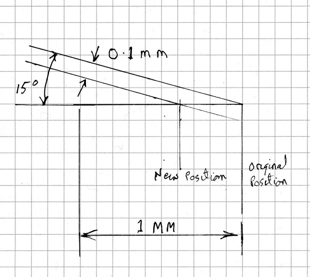
                      The ability if a taper to lock depends on the materials used, the finish on the faces, the taper angle and the presence or absence of any lubricant. The linear position will change if you take some material off the surface of one or both parts. It will also change if there is any bedding in of uneven surfaces. If this is what you are concerned with then the formula is the wear divided by the sine of the half angle. As an example if you machined off 0.1mm or had the equivalent wear and the taper half angle is 15 degrees then the linear movement along the taper will change by 0.1/sin(15) = 0.38mm.

                      Martin C

                      #482655
                      Michael Gilligan
                      Participant
                        @michaelgilligan61133
                        Posted by Martin Connelly on 28/06/2020 09:37:57:

                        […]

                        As an example if you machined off 0.1mm or had the equivalent wear and the taper half angle is 15 degrees then the linear movement along the taper will change by 0.1/sin(15) = 0.38mm.

                        Martin C

                        .

                        … and if the taper half-angle was 90° then that linear movement would be 0.1mm

                        which I think nicely demonstrates my point angel

                        MichaelG.


                        Edited By Michael Gilligan on 28/06/2020 10:27:38

                        #482660
                        Nicholas Farr
                        Participant
                          @nicholasfarr14254
                          Posted by Martin Connelly on 28/06/2020 09:37:57:

                          The ability if a taper to lock depends on the materials used, the finish on the faces, the taper angle and the presence or absence of any lubricant. The linear position will change if you take some material off the surface of one or both parts. It will also change if there is any bedding in of uneven surfaces. If this is what you are concerned with then the formula is the wear divided by the sine of the half angle. As an example if you machined off 0.1mm or had the equivalent wear and the taper half angle is 15 degrees then the linear movement along the taper will change by 0.1/sin(15) = 0.38mm.

                          Martin C

                          Hi, here is a sketch that proves the calculation. The squares in the real world are 5mm, but represent 0.1mm.

                          taper sketch001.jpg

                          Regards Nick.

                          Edited By Nicholas Farr on 28/06/2020 11:08:06

                          #482664
                          not done it yet
                          Participant
                            @notdoneityet

                            I would think that the fit will be very consistent – unless one fits a taper into a socket at different temperatures. Most certainly one can achieve a fair ‘shrink-fit’ if the socket is appreciably warmer than the taper plugged in! There is a very large surface area to be ‘distorted’ on most working tapers which are a good fit, likely less so if your taper came from B———-d.🙂

                            Fit will be less precise as the taper angle decreases – think of the case as the taper angle approaches, and arrives at, zero (or as the taper arrives at 90 degrees).🙂

                            #482665
                            C J
                            Participant
                              @cj88518

                              Thank you Martin,

                              That gives me an idea of the linear movement that could occur.

                              As it will only be driving a small carbon fibre disc I don’t expect the hub to experience any serious torque, or slip, but most likely I will remove and refit it a few times to adjust the inlet port timing.

                              #482668
                              C J
                              Participant
                                @cj88518

                                I am constantly surprised by the depth of knowledge to be found on this forum.

                                #482675
                                Hopper
                                Participant
                                  @hopper

                                  If you want positive location you could use the vernier cam gear principle used on Manx Nortons etc. A ring of say 20 holes drilled in your disc mates with a ring of 19 holes in the mounting flange. An indexing pin allows tiny incremental adjustment and then a lock nut anchors it all in position.

                                  Edited By Hopper on 28/06/2020 11:36:02

                                  #482678
                                  C J
                                  Participant
                                    @cj88518

                                    Love that idea but I’m locked into using a ready made disc, and I once had a go on a Manx Norton albeit round a field!

                                    #482681
                                    Neil Lickfold
                                    Participant
                                      @neillickfold44316

                                      Actually the incycle variation on a single cylinder 2 stroke engine is very real. Using light weight materials for the disc will be in your favour. The advantage of a driving taper over a shaft and keyway , is that you can make adjustments to the opening or the closing while maintaining the same total induction duration. A good way to make these is to make a set of gauges, male and female. These can be used to make the shaft the correct taper size and the other to make the hub the correct taper size. If at any other time you need another hub for a different plate, you can just swap them out and see the difference in performance and swap back without too much fuss. Taking your time and being careful there is no reason for you not to be able to achieve a 0.05mm linear position on any of the interchangeable parts you make.

                                      Neil

                                      #482715
                                      old mart
                                      Participant
                                        @oldmart

                                        I seem to remember that the few Japanese manufacturers of bikes with disc valve motors had floating discs on some kind of spline.

                                        #482720
                                        C J
                                        Participant
                                          @cj88518

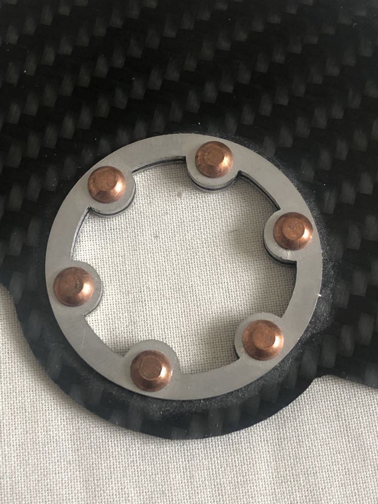
                                          That's right, but for added fun my disc is driven by six lobes as shown.

                                          disc.jpg

                                          #482723
                                          Paul Kemp
                                          Participant
                                            @paulkemp46892

                                            Just to throw a curved ball, the repeatability of how far a female taper seats up a male taper will also depend on the rigidity of the female component and the force used to push it up the taper. This property is used to good effect on large high power taper fit couplings that have no key but rely on the "push up" of the female over the male. The elastic properties of the material mean the greater the push up the greater the "grip". In your application the difference will probably be only microns but to gaurantee a consistent linear position a consistent seating force would be needed.

                                            Paul.

                                            #482725
                                            C J
                                            Participant
                                              @cj88518

                                              Curve ball accepted but not to mention the dreaded galling that can also occur

                                              And to misquote a Monty Python sketch “No one expects the dreaded galling”

                                              Edited By C J on 28/06/2020 15:23:09

                                              #482737
                                              Nicholas Farr
                                              Participant
                                                @nicholasfarr14254

                                                Hi, referring to Paul Kemp's post above, I've known of machines that have gears on very shallow tapers without keys or pins grubs screws etc. They have to be fitted by extremely high pressure oil between the gear and shaft while being pressed home. The oil expands the gear by a few microns while the oil is pumped into a hole down the centre of the shaft and out to the joint line, no galling occurs, but of course accuracy of both parts has to be very good and the oil pressure has to be released before the pushing on pressure they can only be removed (without cutting them) by the reverse proceedure.

                                                Regards Nick.

                                                Edited By Nicholas Farr on 28/06/2020 16:56:58

                                                #482740
                                                Howard Lewis
                                                Participant
                                                  @howardlewis46836

                                                  My tester at C A V had been on Air Sea Rescue launches. Unlike others, his boat never had a propshaft failure, because he dispensed with the key, and lapped the propellor to the shaft; maximum contact area and no stress raiser!

                                                  Anyone who thinks that tapers don't grip has never tried removing the rear brake drum from a Ford or Vauxhall semi floating half shaft!

                                                  Howard

                                                  #482830
                                                  Kiwi Bloke
                                                  Participant
                                                    @kiwibloke62605
                                                    Posted by Nicholas Farr on 28/06/2020 16:54:25:

                                                    Hi, referring to Paul Kemp's post above, I've known of machines that have gears on very shallow tapers without keys or pins grubs screws etc. They have to be fitted by extremely high pressure oil between the gear and shaft while being pressed home. The oil expands the gear by a few microns while the oil is pumped into a hole down the centre of the shaft and out to the joint line, no galling occurs, but of course accuracy of both parts has to be very good and the oil pressure has to be released before the pushing on pressure they can only be removed (without cutting them) by the reverse proceedure.

                                                    Regards Nick.

                                                    Edited By Nicholas Farr on 28/06/2020 16:56:58

                                                    This technique is also sometimes used to fit high-precision anti-friction bearings, eg on lathes. The inner race can thereby be increased in diameter to achieve the radial clearance desired (which I assume is none – or less, ie pre-load).

                                                    #482835
                                                    Kiwi Bloke
                                                    Participant
                                                      @kiwibloke62605

                                                      I suppose the rather unhelpful answer is that the axial positioning repeatability is as consistent as all the variables relevant to the fitting-up procedure. I would think that those (eg torque applied to draw-bar or equivalent, lubrication, etc) would swamp inconsistencies attributable to joint characteristics, material distortion, etc.. This assumes the mating parts are well-made, of course.

                                                    Viewing 25 posts - 1 through 25 (of 32 total)
                                                    • Please log in to reply to this topic. Registering is free and easy using the links on the menu at the top of this page.

                                                    Advert

                                                    Latest Replies

                                                    Home Forums General Questions Topics

                                                    Viewing 25 topics - 1 through 25 (of 25 total)
                                                    Viewing 25 topics - 1 through 25 (of 25 total)

                                                    View full reply list.

                                                    Advert

                                                    Newsletter Sign-up