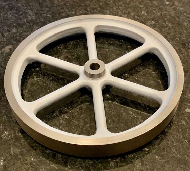
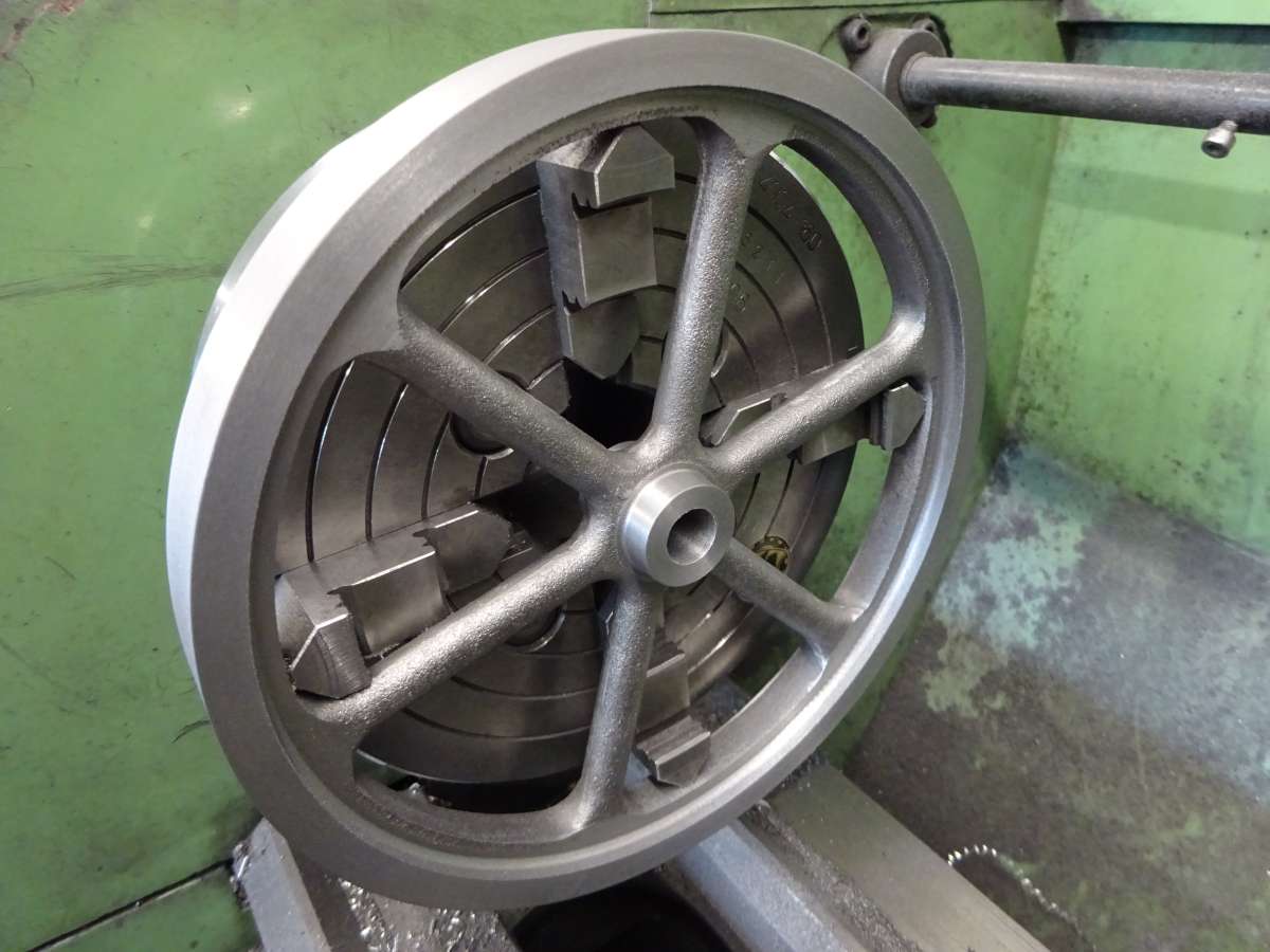
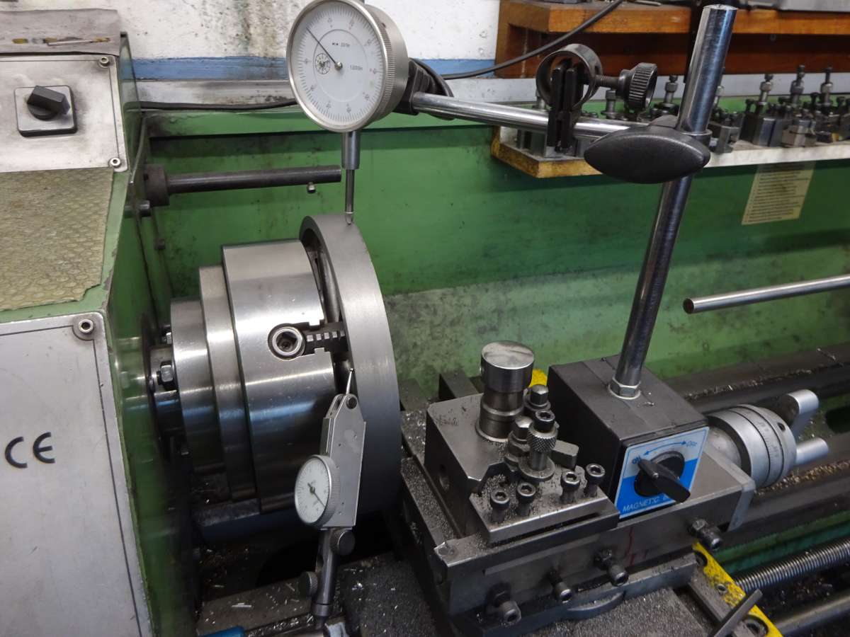
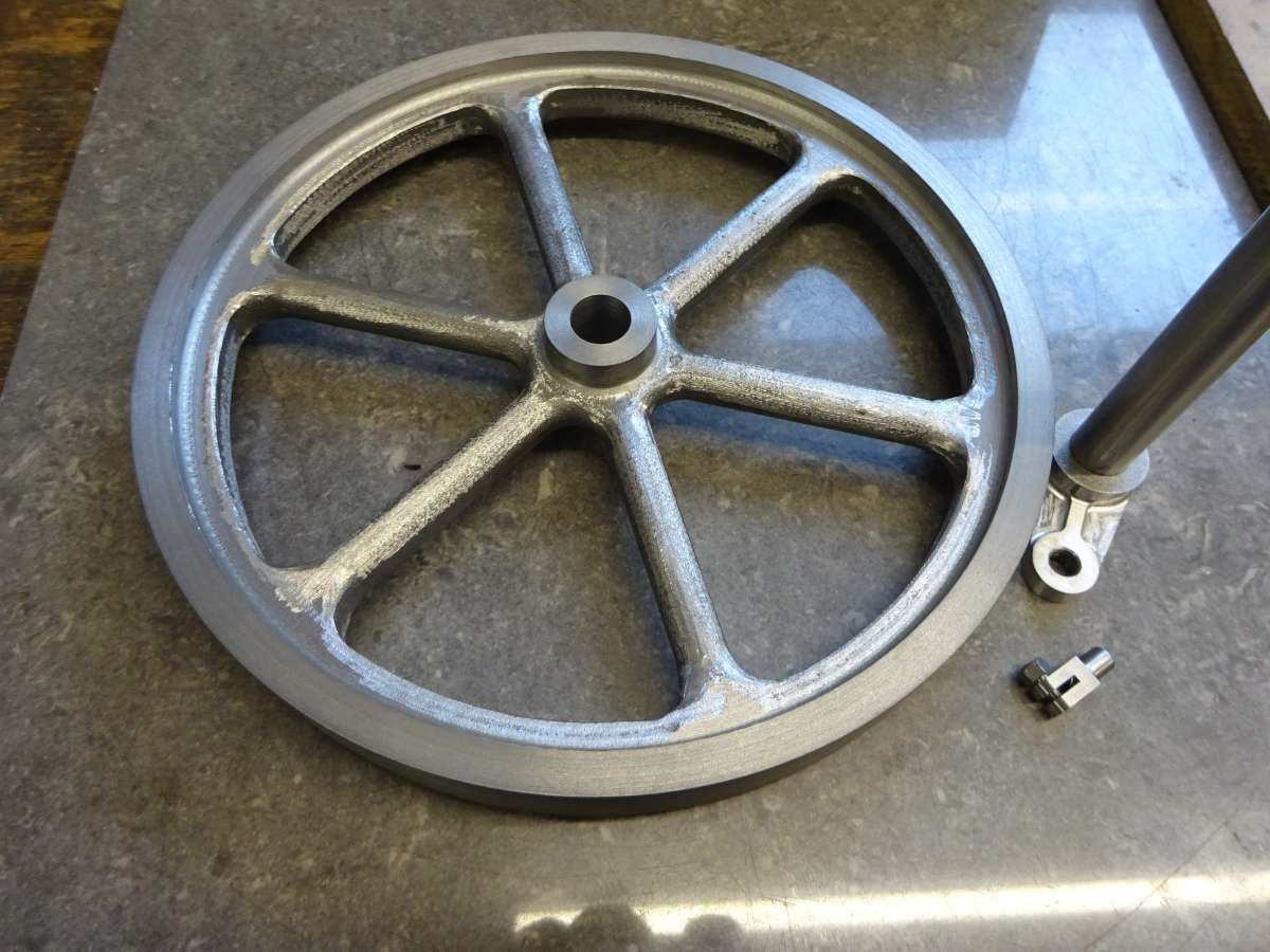
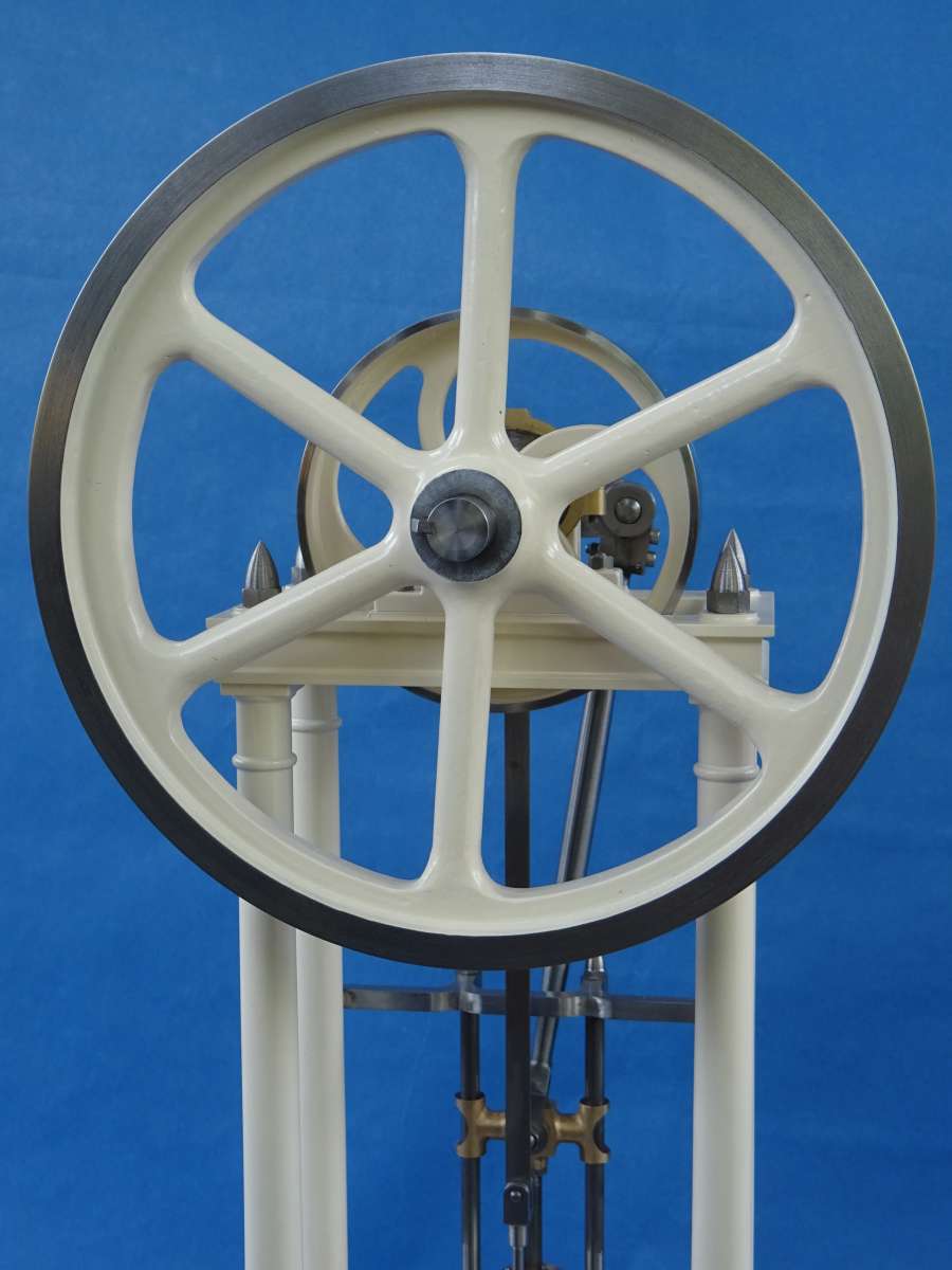
Stuart Twin Victoria (Princess Royal) Mill Engine
Stuart Twin Victoria (Princess Royal) Mill Engine
- This topic has 1,285 replies, 34 voices, and was last updated 26 May 2025 at 06:48 by
 JasonB.


- Please log in to reply to this topic. Registering is free and easy using the links on the menu at the top of this page.
Latest Replies
-
- Topic
- Voices
- Last Post
-
-
Odd RAF Specialist Tool?
Started by:
Martin King 2
in: Help and Assistance! (Offered or Wanted)
- 8
-
10 August 2025 at 01:33
Paul Kemp
-
My week this week! My workshop videos
1
2
…
11
12
Started by:
Phil Whitley
in: The Tea Room
- 15
-
10 August 2025 at 01:15
howardb
-
Help Wire 3 Phase 2 Speed Motor
1
2
Started by:
Allan Day
in: Electronics in the Workshop
- 16
-
10 August 2025 at 01:06
Wade Beatty
-
Which Carbide Lathe Tools?
Started by:
MarkS
in: Beginners questions
- 14
-
9 August 2025 at 23:33
IanT
-
Stuart Restoration
Started by:
Richard Simpson
in: Stationary engines
- 3
-
9 August 2025 at 23:07
Richard Simpson
-
Mill drill power feed
Started by:
Andy Sproule
in: General Questions
- 7
-
9 August 2025 at 22:29
Diogenes
-
Being Nosey From Model Boats
Started by:
Richard Simpson
in: Introduce Yourself – New members start here!
- 3
-
9 August 2025 at 21:55
Harry Wilkes
-
rotational motion into linear motion – force calculation?
Started by:
ell81
in: Beginners questions
- 9
-
9 August 2025 at 20:55
Martin Kyte
-
Odd Strain Gauge for Concrete?
Started by:
Martin King 2
in: Help and Assistance! (Offered or Wanted)
- 5
-
9 August 2025 at 20:09
V8Eng
-
BENCHMASTER SENIOR DONKEY SAW
Started by:
carcav13
in: Beginners questions
- 1
-
9 August 2025 at 18:19
carcav13
-
Cheap DRO
Started by:
Steve355
in: General Questions
- 2
-
9 August 2025 at 17:58
Wink Hackman
-
Model Engineer Magazine Collection
Started by:
mfengine1
in: Books
- 9
-
9 August 2025 at 17:30
mfengine1
-
Superheaters
Started by:
Garry Coles
in: General Questions
- 6
-
9 August 2025 at 16:05
duncan webster 1
-
Bandsaw alignment
Started by:
jimmy b
in: Workshop Tools and Tooling
- 1
-
9 August 2025 at 14:11
jimmy b
-
Just How Many File Types Do We Need?
Started by:
Nigel Graham 2
in: The Tea Room
- 13
-
9 August 2025 at 12:53
duncan webster 1
-
Boiler hydraulic test 4 hours
1
2
Started by:
endckr111
in: Stationary engines
- 13
-
9 August 2025 at 12:53
endckr111
-
Suggestions for next clock build?
Started by:
Mike Crossfield
in: Clocks and Scientific Instruments
- 7
-
9 August 2025 at 10:45
Mike Crossfield
-
quality 3 and 4 jaw chucks
Started by:
Steve Huckins
in: Workshop Tools and Tooling
- 9
-
9 August 2025 at 08:55
Chris Crew
-
UK Steel Supplier? 125 x 125 x 50 BMS
1
2
Started by:
MarkS
in: General Questions
- 14
-
9 August 2025 at 07:42
MarkS
-
Boiler Design – issue 4765
1
2
…
10
11
Started by:
Charles Lamont
in: Model Engineer & Workshop
- 29
-
9 August 2025 at 07:37
MEinThailand
-
The strange phenomenon of Liquid Death
Started by:
Michael Gilligan
in: The Tea Room
- 9
-
8 August 2025 at 21:46
Michael Gilligan
-
Obscure Thread
Started by:
simondavies3
in: Hints And Tips for model engineers
- 9
-
8 August 2025 at 19:03
old mart
-
Miniature parts maker in Leicester?
Started by:
wilson logan 1
in: Help and Assistance! (Offered or Wanted)
- 4
-
8 August 2025 at 15:31
JasonB
-
Whats app
Started by:
duncan webster 1
in: The Tea Room
- 4
-
8 August 2025 at 15:28
Russell Eberhardt
-
MD65 leadscrew cross-slide stuck in nut
Started by:
leov
in: Manual machine tools
- 9
-
7 August 2025 at 20:54
old mart
-
Odd RAF Specialist Tool?
Latest Issue

Newsletter Sign-up
Latest Replies
- Odd RAF Specialist Tool?
- My week this week! My workshop videos
- Help Wire 3 Phase 2 Speed Motor
- Which Carbide Lathe Tools?
- Stuart Restoration
- Mill drill power feed
- Being Nosey From Model Boats
- rotational motion into linear motion – force calculation?
- Odd Strain Gauge for Concrete?
- BENCHMASTER SENIOR DONKEY SAW

