Stuart Twin Victoria (Princess Royal) Mill Engine
Stuart Twin Victoria (Princess Royal) Mill Engine
- This topic has 1,258 replies, 33 voices, and was last updated 6 May 2025 at 06:49 by
 JasonB.
![20220708_144841[1].jpg](/wp-content/uploads/sites/4/images/member_albums/44290/911107.jpg "20220708_144841[1].jpg")


- Please log in to reply to this topic. Registering is free and easy using the links on the menu at the top of this page.
Latest Replies
-
- Topic
- Voices
- Last Post
-
-
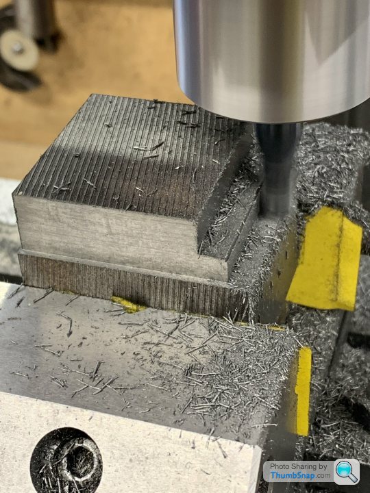
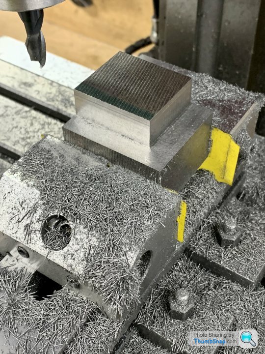
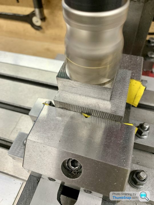
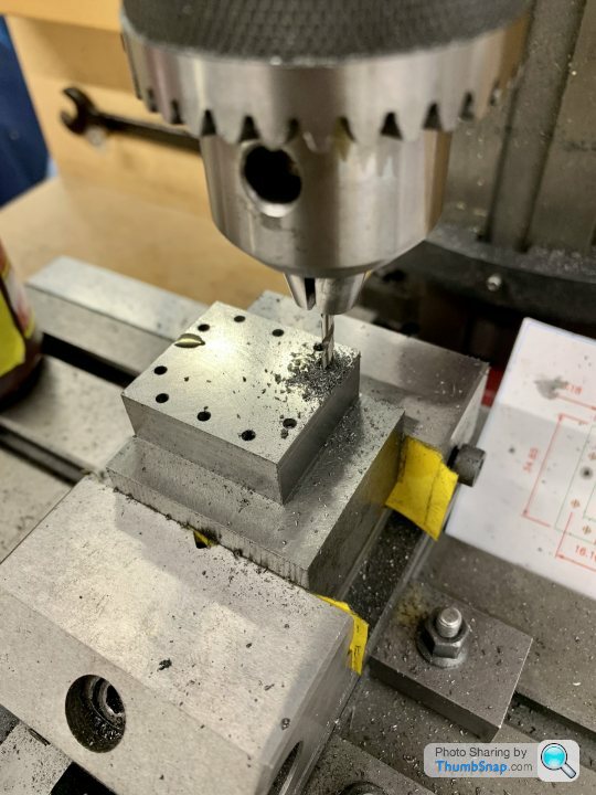
Stopping milling chips going everyehere
1
2
Started by:
petro1head
in: General Questions
- 22
-
7 May 2025 at 05:12
petro1head
-
Photos
Started by:
petro1head
in: Website Questions, Comments, and Suggestions
- 4
-
7 May 2025 at 05:06
petro1head
-
Kia Ora from the bottom of the world. Tool hoarder & enthusiast.
Started by:
gimme72
in: Introduce Yourself – New members start here!
- 5
-
7 May 2025 at 01:37
gimme72
-
Antique Ornamental Treadle lathe what is it
Started by:
Bazyle
in: Workshop Tools and Tooling
- 1
-
7 May 2025 at 00:09
Bazyle
-
Building Bernard Tekippe’s Precision Regulator
1
2
3
Started by:
Chris Raynerd 2
in: Clocks and Scientific Instruments
- 12
-
6 May 2025 at 23:29
Chris Raynerd 2
-
An Original Stephenson Model
Started by:
David Viewing 1
in: Miscellaneous models
- 4
-
6 May 2025 at 23:25
Nigel Graham 2
-
bolts harness and head shearing?
Started by:
jon hill 3
in: Related Hobbies including Vehicle Restoration
- 4
-
6 May 2025 at 23:19
Michael Gilligan
-
TALE OF TWO VIPERS
Started by:
dean clarke 2
in: I/C Engines
- 7
-
6 May 2025 at 23:15
dean clarke 2
-
Rain Gutter Power
Started by:
Michael Gilligan
in: Suggested Online Resources
- 7
-
6 May 2025 at 23:04
Nigel Graham 2
-
Amadeal VM25L Uneven Motor Brush Wear
1
2
Started by:
Richard Kirkman 1
in: Help and Assistance! (Offered or Wanted)
- 13
-
6 May 2025 at 21:53
Richard Kirkman 1
-
3D printer choices
1
2
Started by:
Matt Harrington
in: 3D Printers and 3D Printing
- 14
-
6 May 2025 at 21:44
Journeyman
-
Countersinking carbon fibre sheet with my Sieg CNC Mill
Started by:
Sarah F
in: CNC machines, Home builds, Conversions, ELS, automation, software, etc tools
- 6
-
6 May 2025 at 21:30
Sarah F
-
Tweezers..
Started by:
Diogenes
in: General Questions
- 8
-
6 May 2025 at 21:08
Speedy Builder5
-
Clarkson T&C Grinder
Started by:
Ian Owen NZ
in: Manual machine tools
- 4
-
6 May 2025 at 20:31
Ian Owen NZ
-
Purpose of pivot on carburettor linkage ? ?
Started by:
Alan Donovan
in: Help and Assistance! (Offered or Wanted)
- 4
-
6 May 2025 at 19:44
Bazyle
-
Sound effects
Started by:
duncan webster 1
in: Electronics in the Workshop
- 6
-
6 May 2025 at 18:23
SillyOldDuffer
-
Lathe improvements?
1
2
…
4
5
Started by:
Niels Abildgaard
in: Manual machine tools
- 23
-
6 May 2025 at 17:30
Diogenes
-
Boiler Examinations: 7-yearly External Query
1
2
Started by:
Nigel Graham 2
in: Traction engines
- 9
-
6 May 2025 at 15:47
duncan webster 1
-
Confusing motor connections – 240v motor
Started by:
ell81
in: Beginners questions
- 7
-
6 May 2025 at 15:23
Howard Lewis
-
Replacement collet set nut
Started by:
David George 1
in: Workshop Tools and Tooling
- 8
-
6 May 2025 at 12:16
JasonB
-
Mill selection
Started by:
stephenh
in: Beginners questions
- 10
-
6 May 2025 at 11:45
JasonB
-
Kennedy Hexacut machine hacksaw
1
2
Started by:
Leo F Byrne 1
in: Help and Assistance! (Offered or Wanted)
- 17
-
6 May 2025 at 10:54
William Ayerst
-
Half Scale 1/4HP A J Weed Engine
Started by:
JasonB
in: Stationary engines
- 4
-
6 May 2025 at 07:22
JasonB
-
What Did You Do Today 2025
1
2
…
4
5
Started by:
JasonB
in: The Tea Room
- 28
-
6 May 2025 at 07:09
Dell
-
Stuart Twin Victoria (Princess Royal) Mill Engine
1
2
…
50
51
Started by:
Dr_GMJN
in: Work In Progress and completed items
- 33
-
6 May 2025 at 06:49
JasonB
-
Stopping milling chips going everyehere
1
2
Latest Issue

Newsletter Sign-up
Latest Replies
- Stopping milling chips going everyehere
- Photos
- Kia Ora from the bottom of the world. Tool hoarder & enthusiast.
- Antique Ornamental Treadle lathe what is it
- Building Bernard Tekippe’s Precision Regulator
- An Original Stephenson Model
- bolts harness and head shearing?
- TALE OF TWO VIPERS
- Rain Gutter Power
- Amadeal VM25L Uneven Motor Brush Wear

