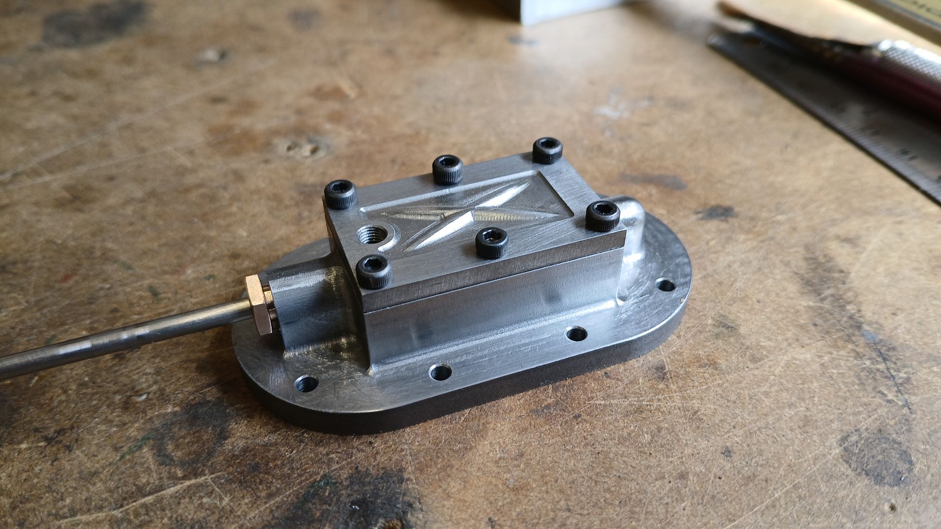
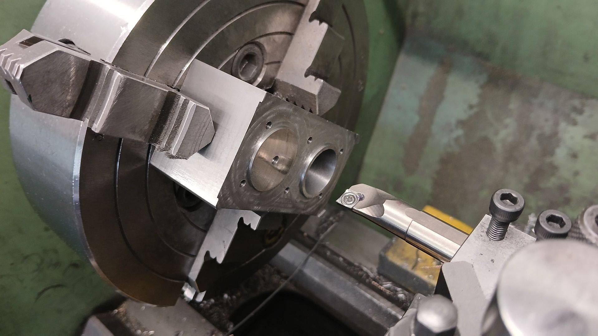
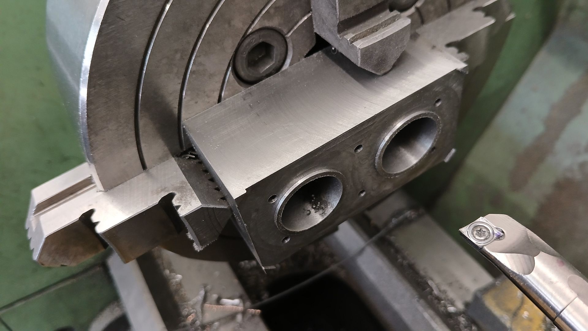
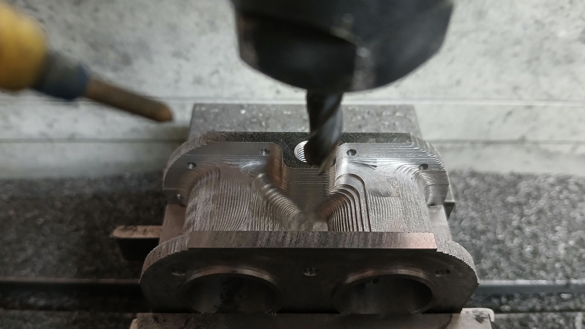
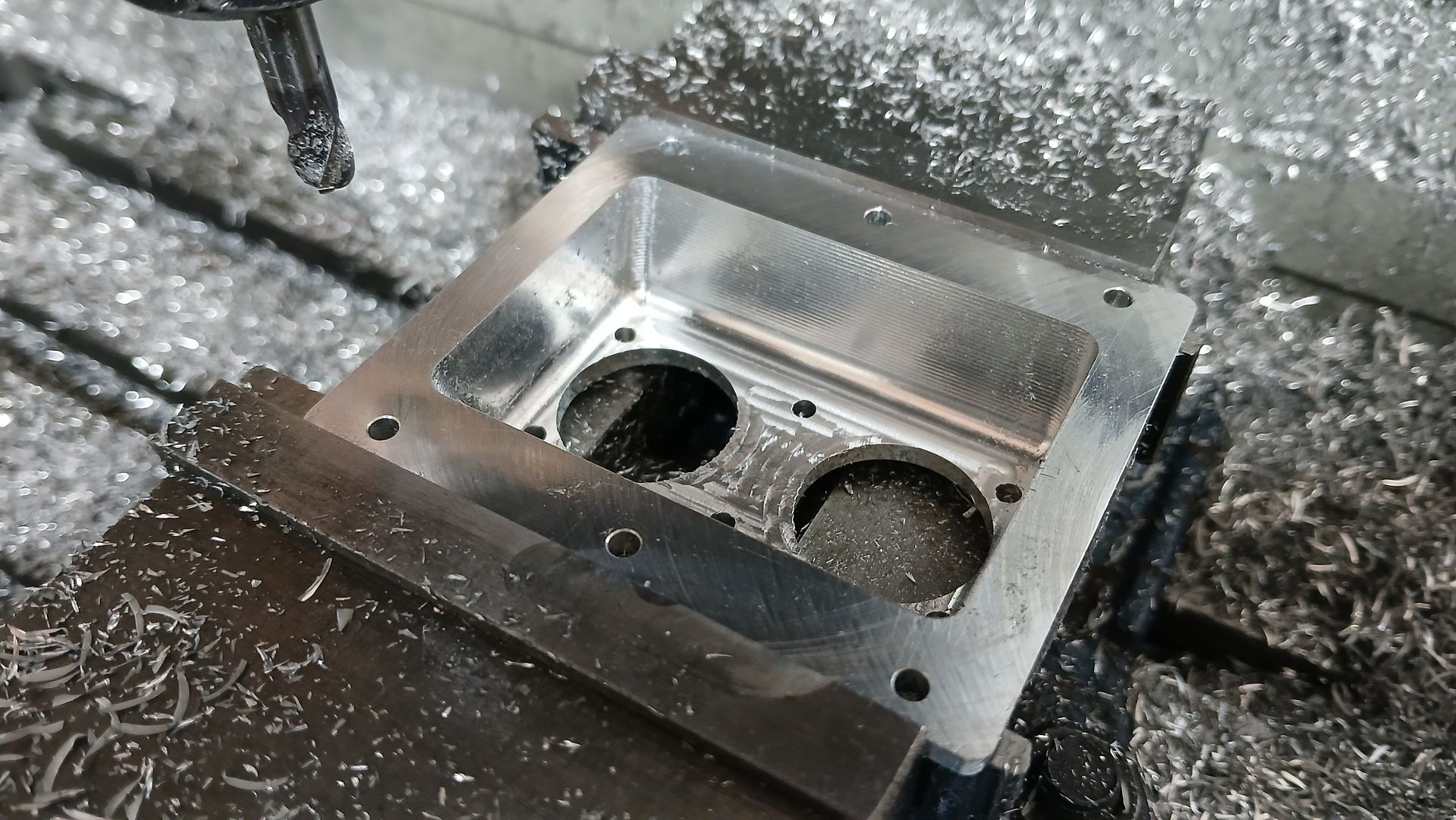
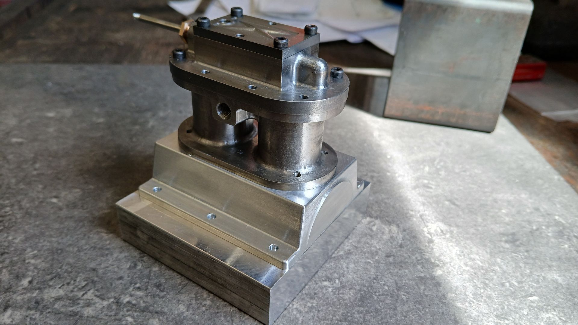
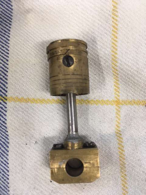
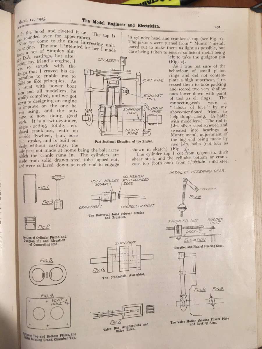
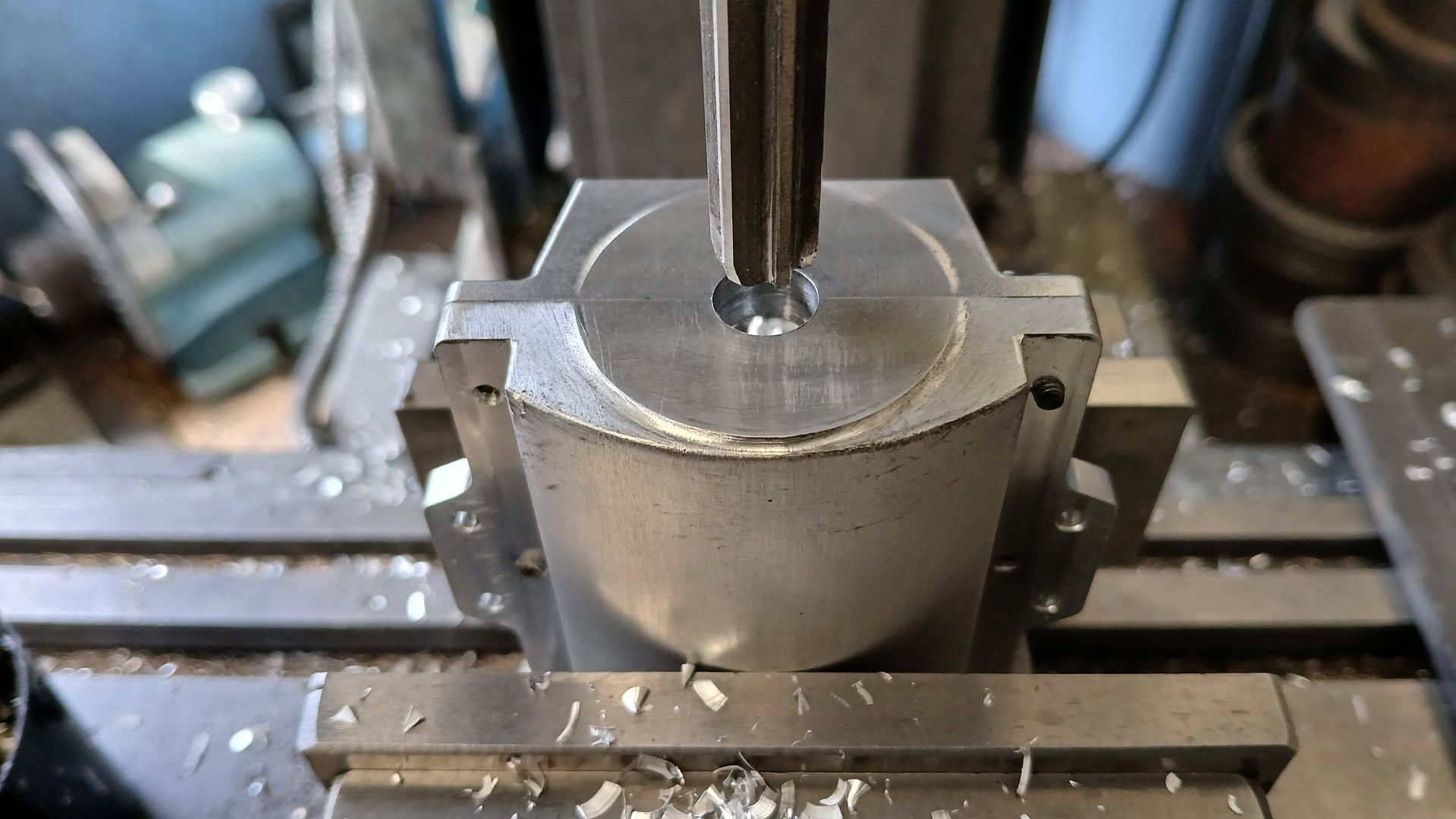
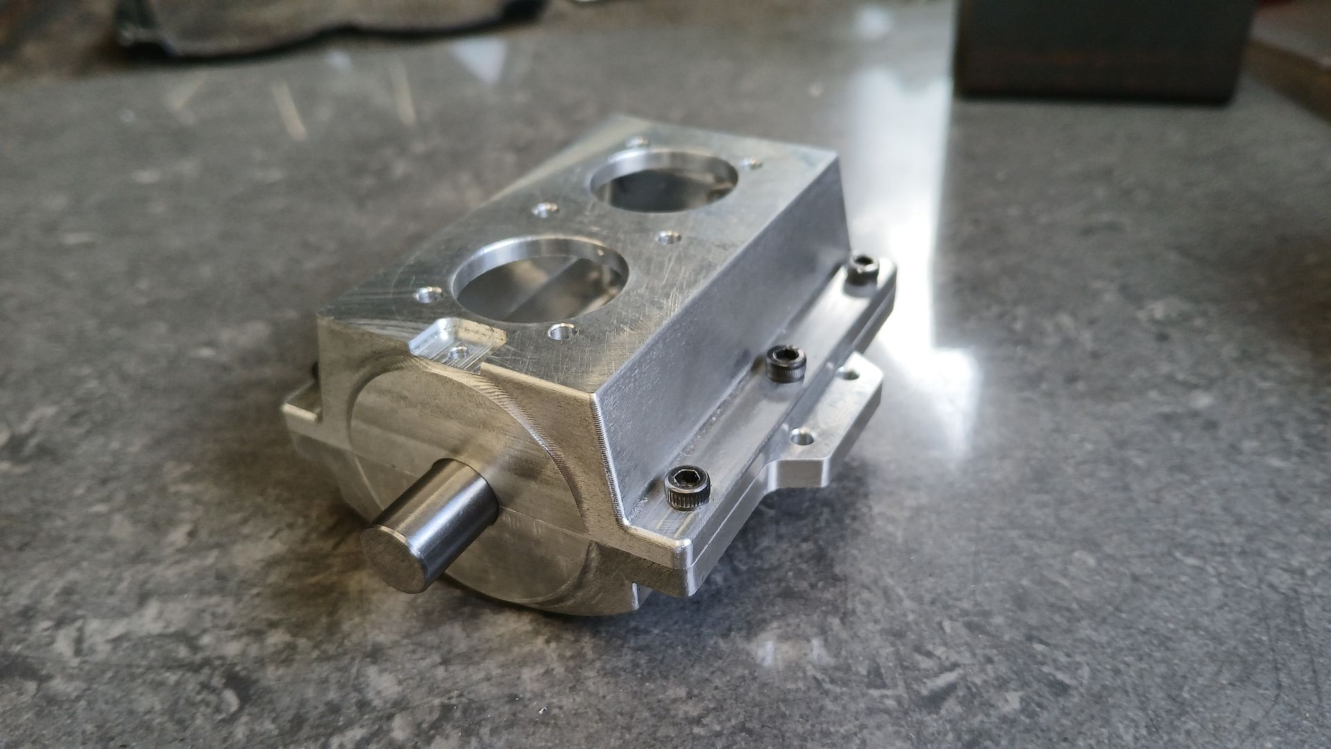
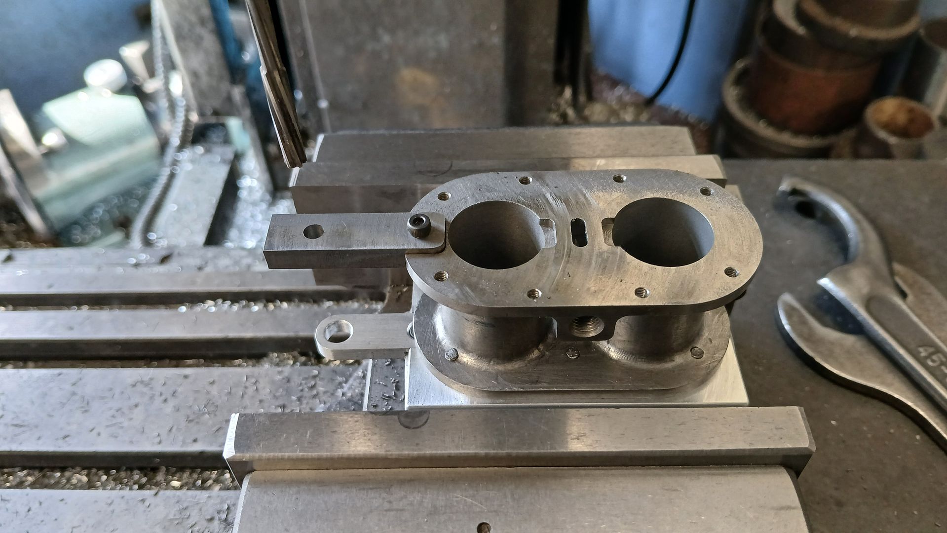
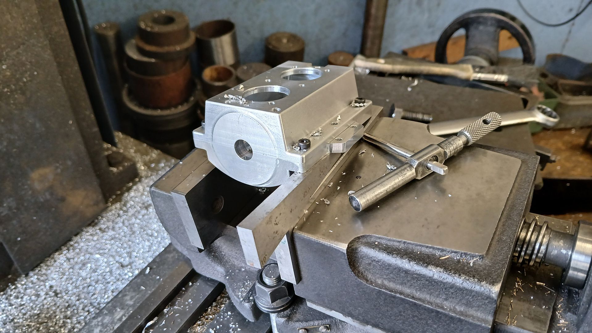
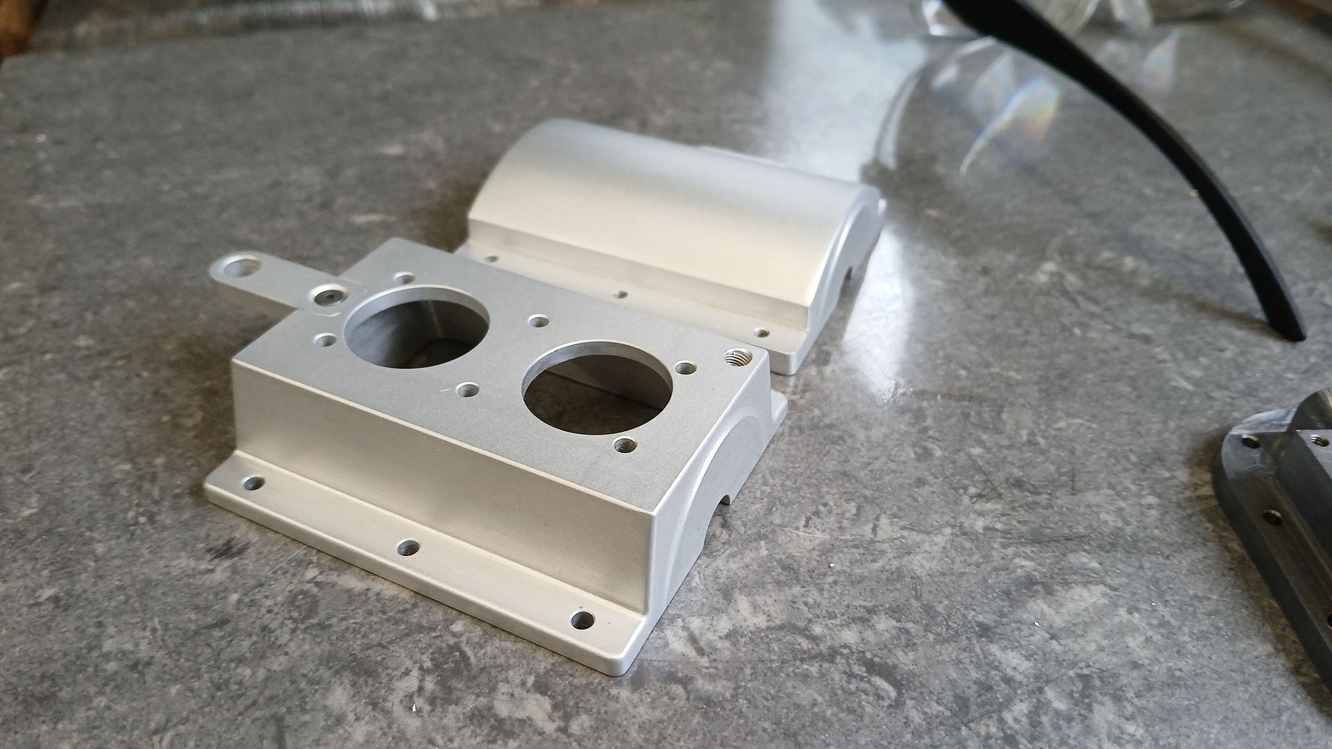
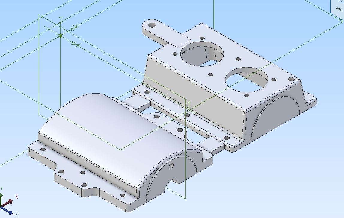
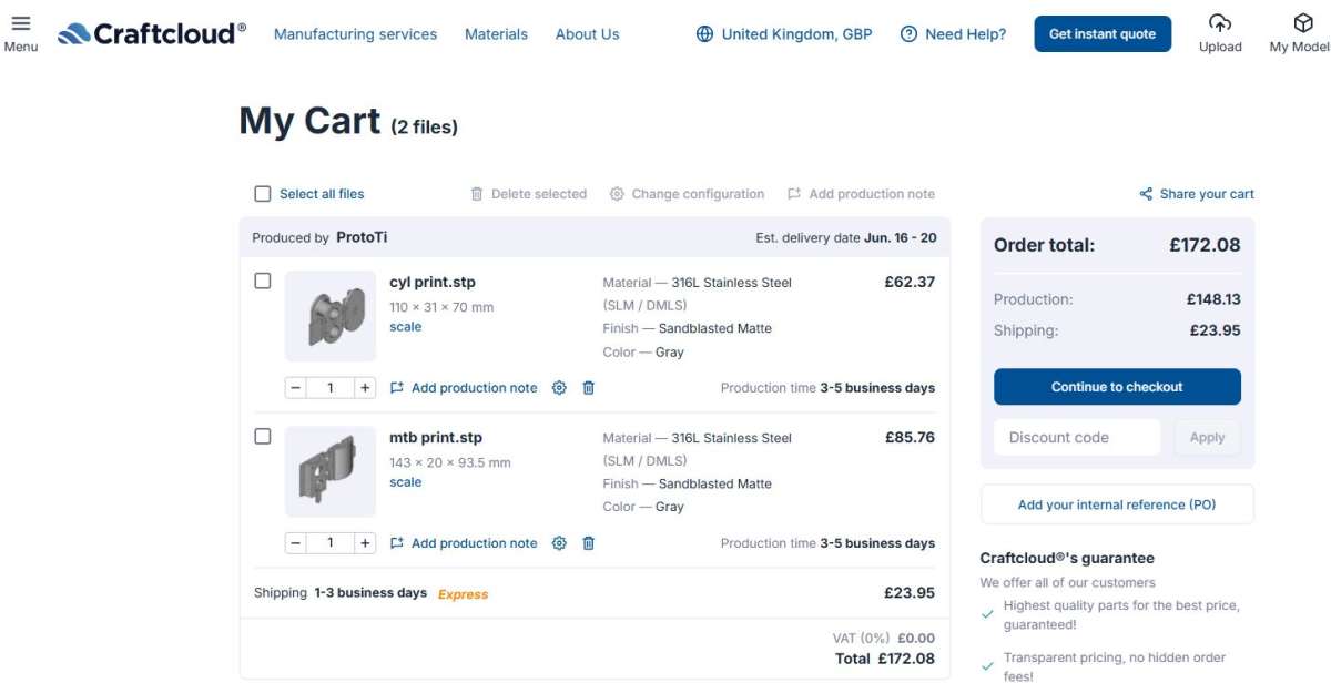
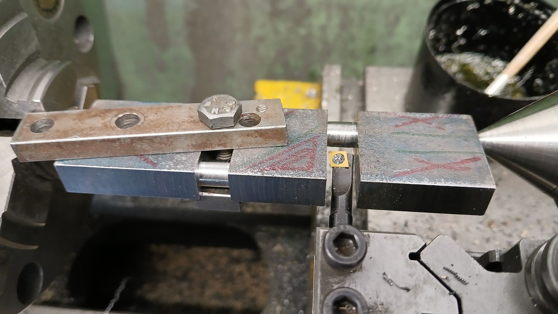
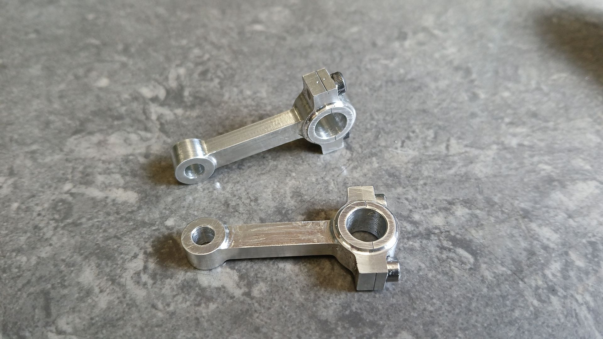
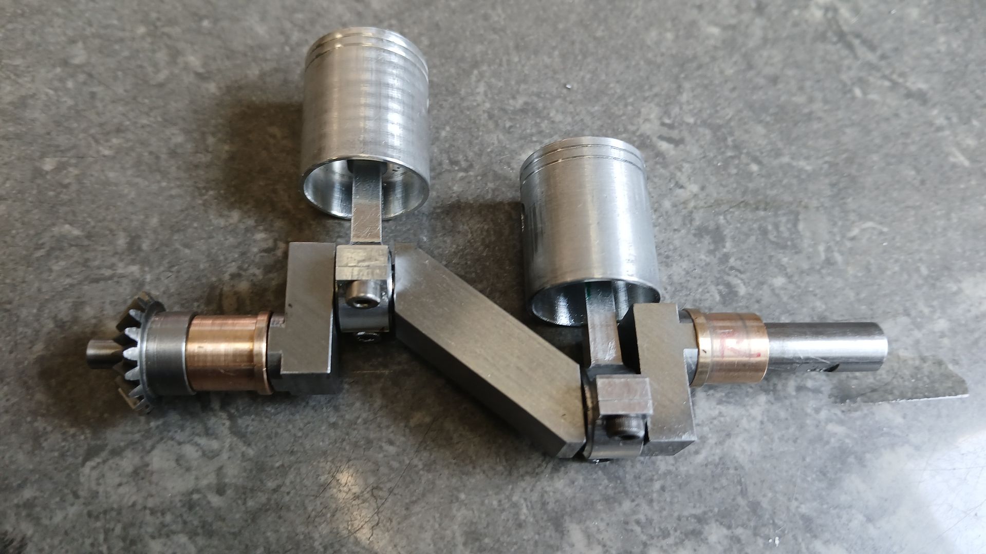
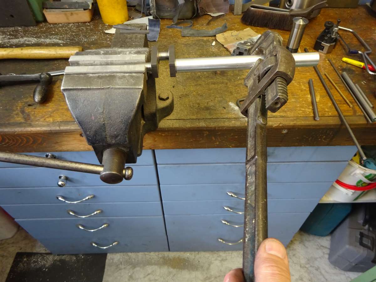
Stuart? MTB 1M
Stuart? MTB 1M
- This topic has 27 replies, 9 voices, and was last updated 17 June 2025 at 18:13 by
 JasonB.
- Please log in to reply to this topic. Registering is free and easy using the links on the menu at the top of this page.
Latest Replies
-
- Topic
- Voices
- Last Post
-
-
Forum search
Started by:
John Purdy
in: Help and Assistance! (Offered or Wanted)
- 1
-
17 June 2025 at 22:48
John Purdy
-
Rotary table question.
Started by:
larry phelan 1
in: Beginners questions
- 6
-
17 June 2025 at 21:50
Dave S
-
How many spokes do I really need?
Started by:
Fulmen
in: Related Hobbies including Vehicle Restoration
- 2
-
17 June 2025 at 21:21
Fulmen
-
VERY SAD NEWS
Started by:
Howard Lewis
in: The Tea Room
- 2
-
17 June 2025 at 21:11
bernard towers
-
Dead flies on the front of the car
Started by:
Plasma
in: The Tea Room
- 19
-
17 June 2025 at 18:53
Mike Poole
-
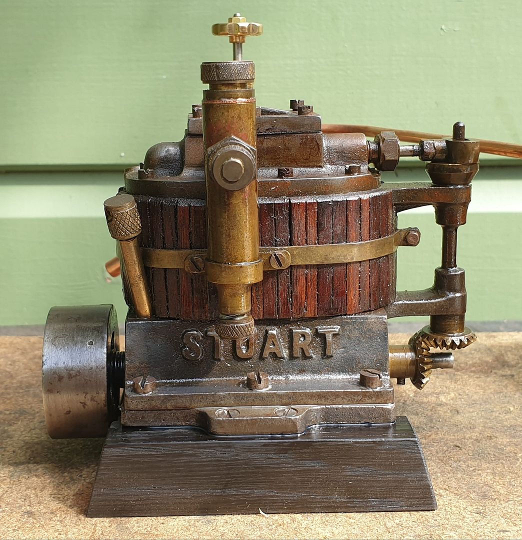
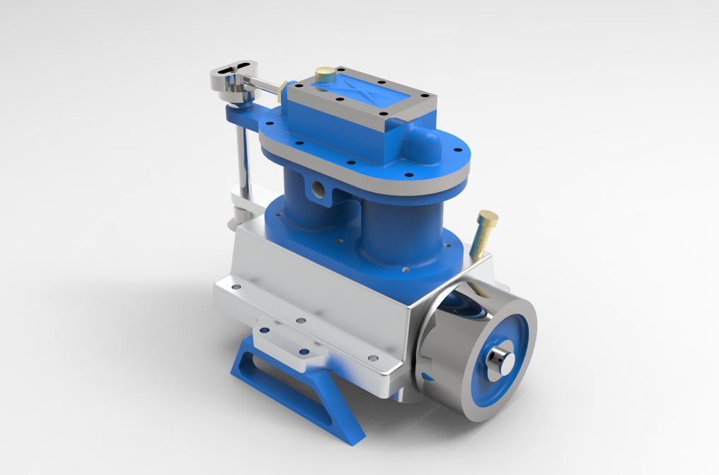
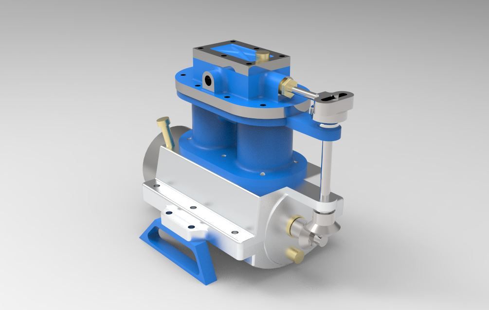
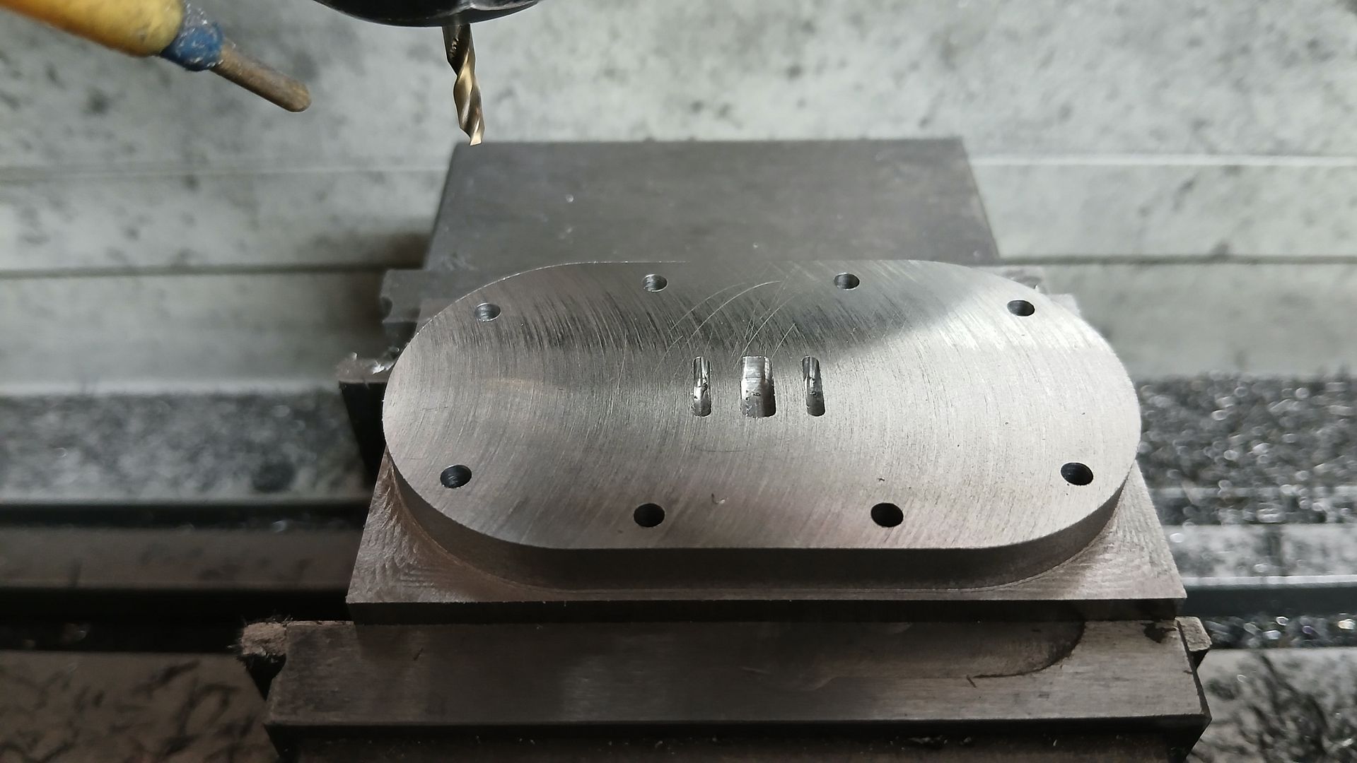
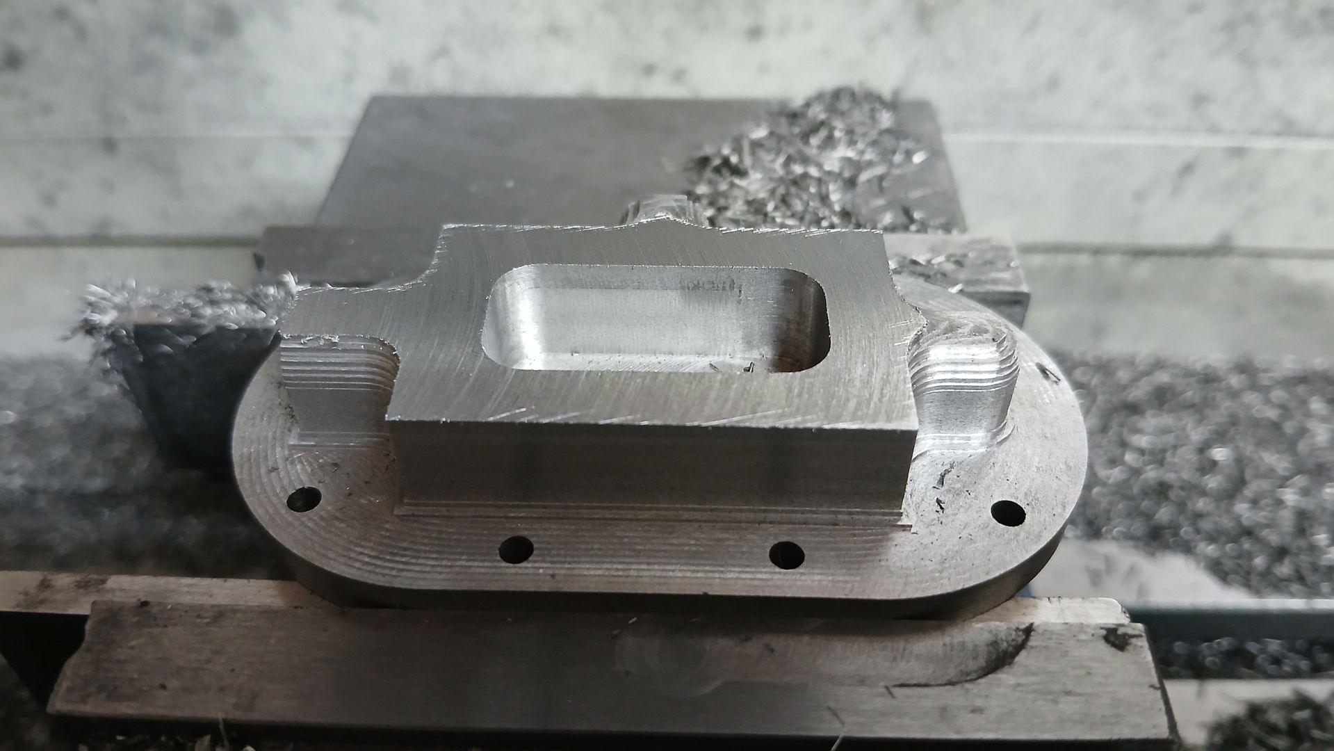
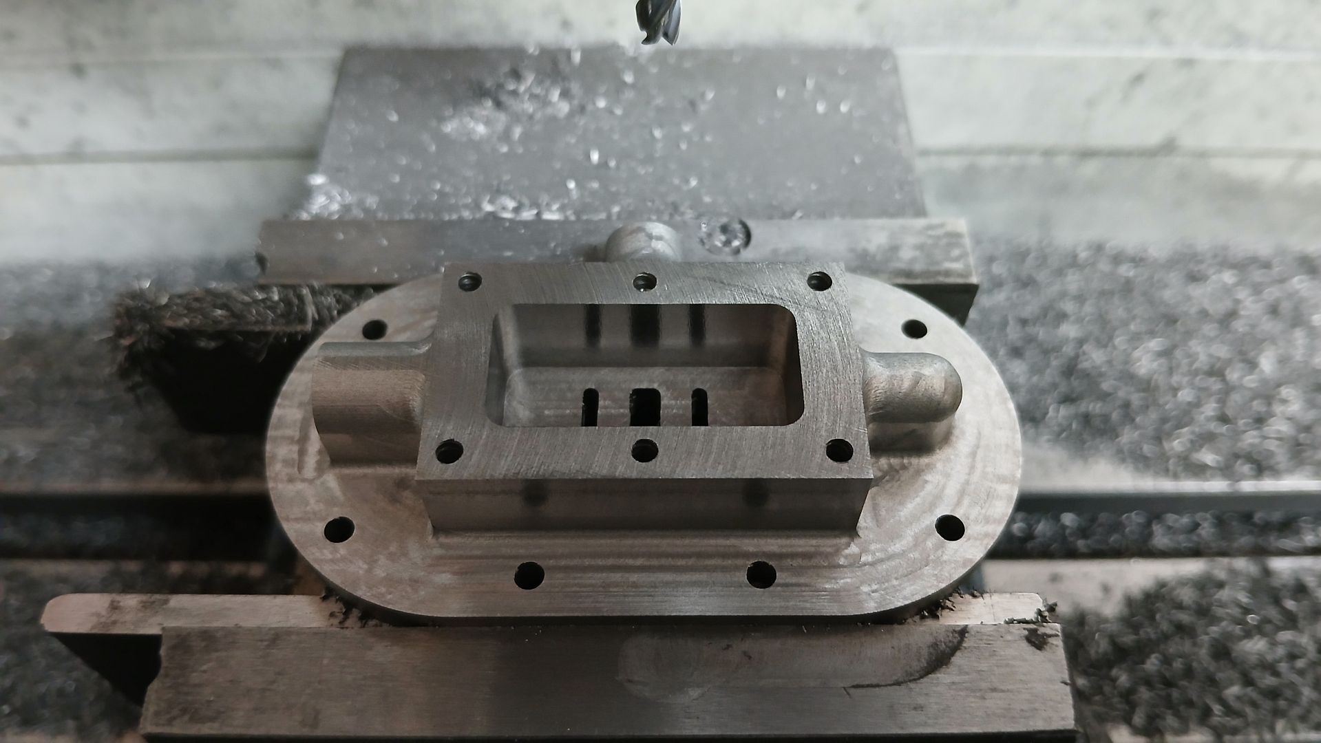
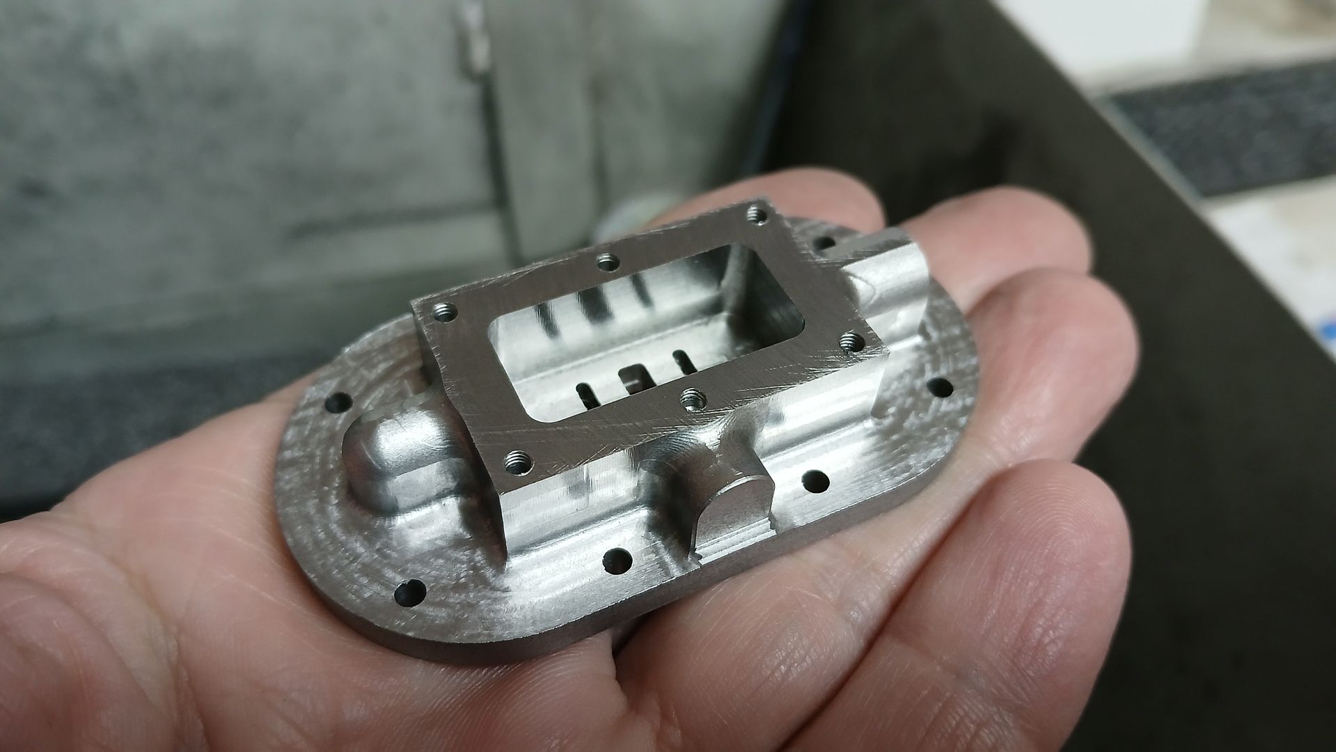
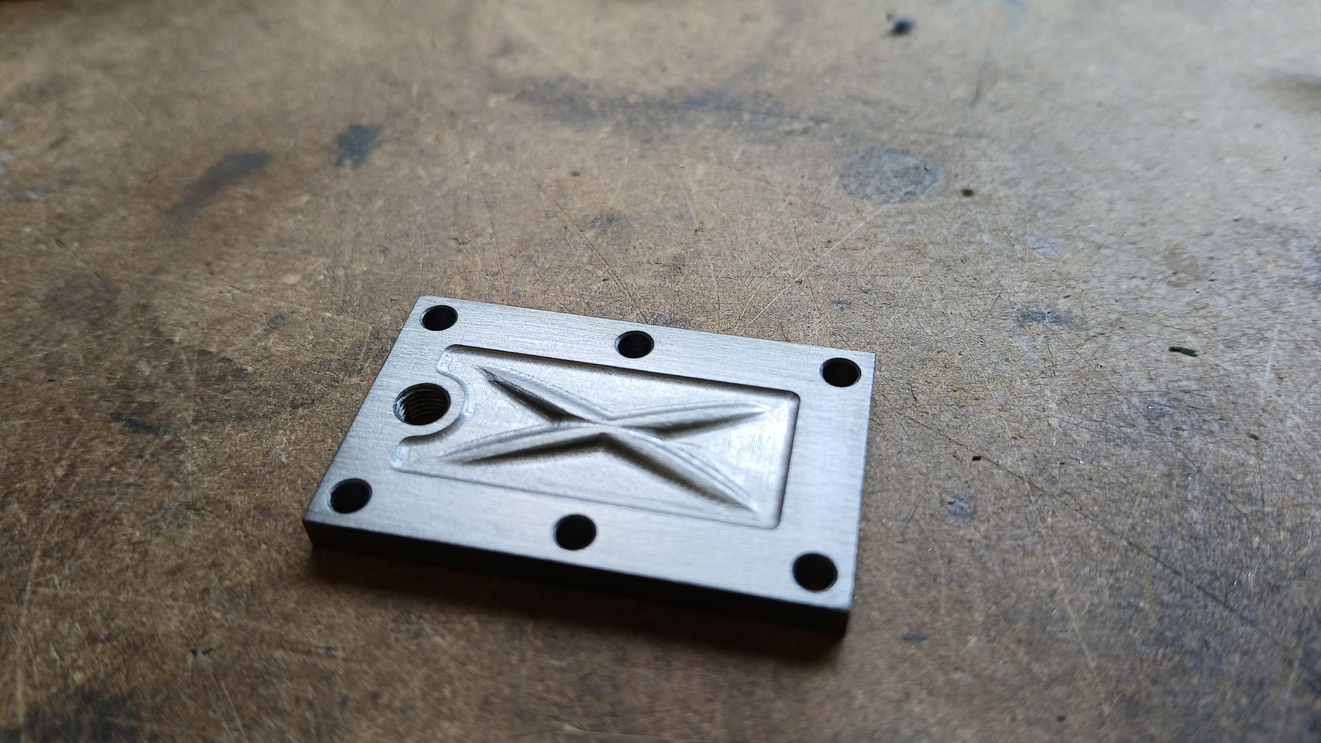
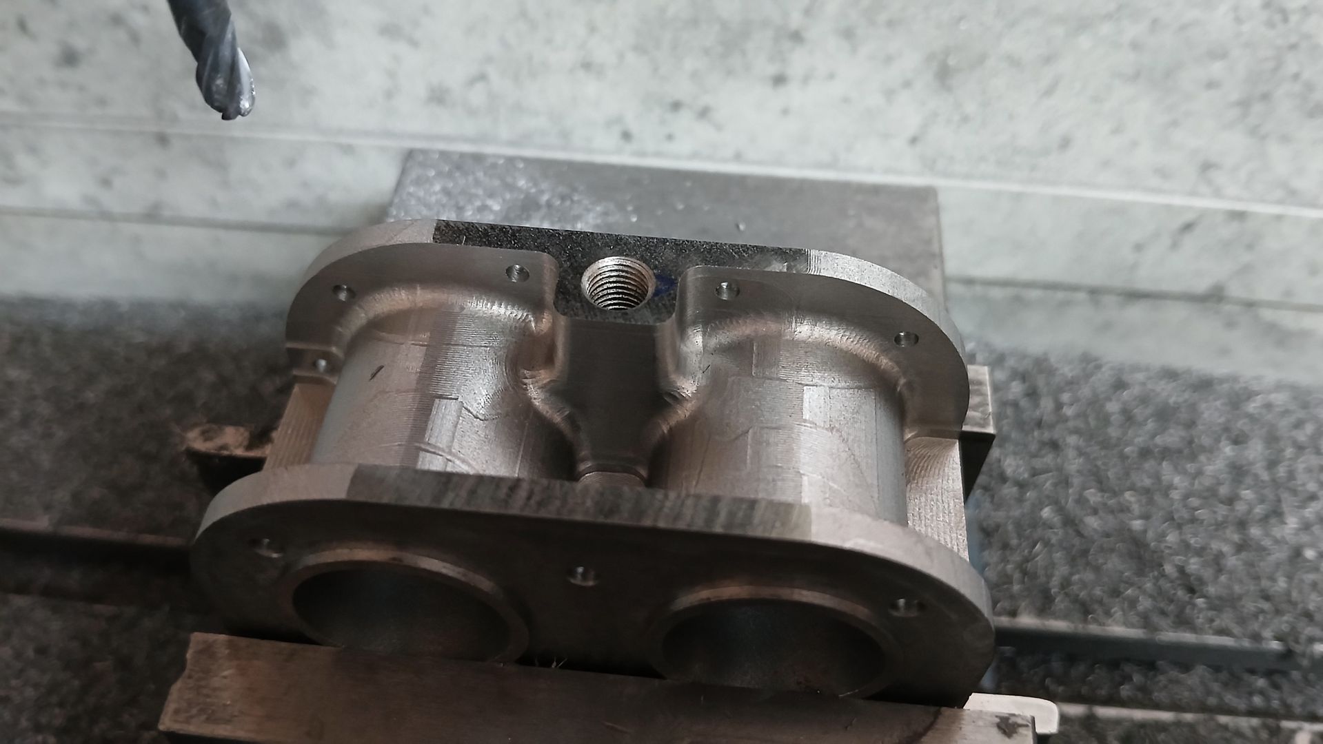
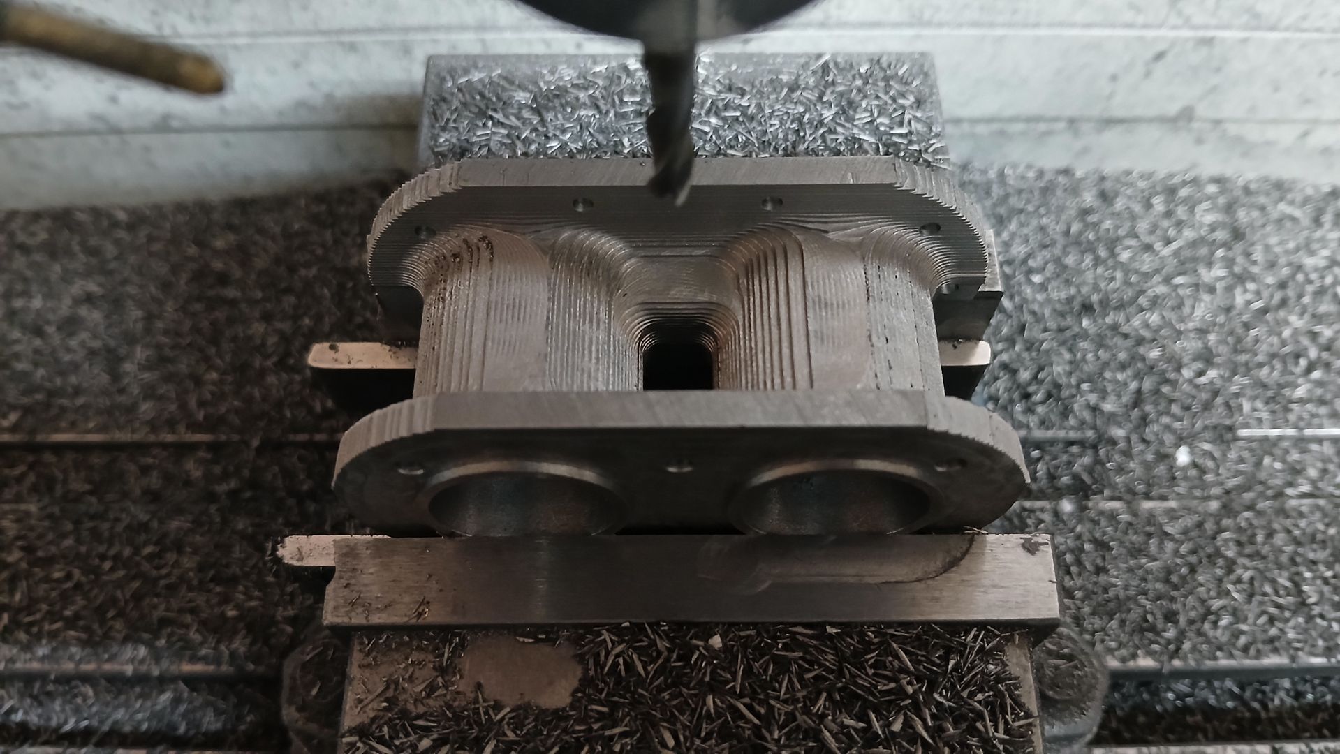
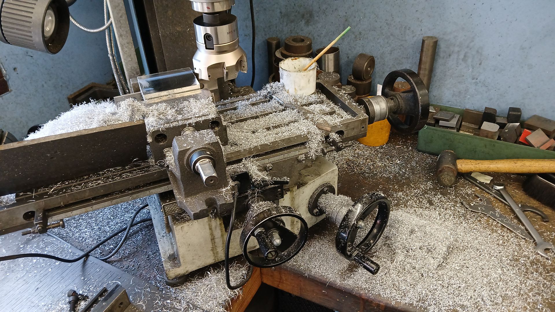
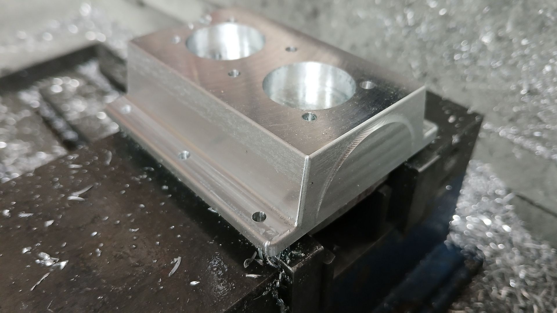
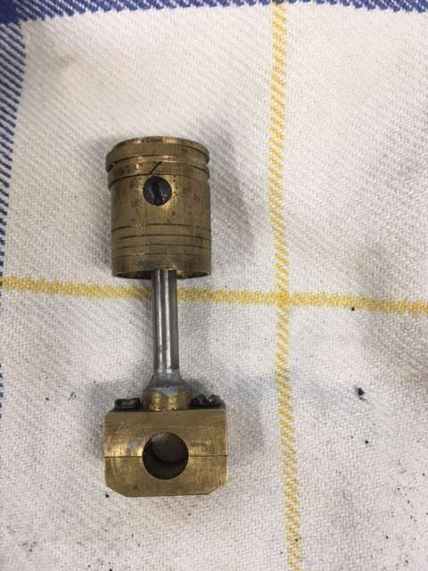
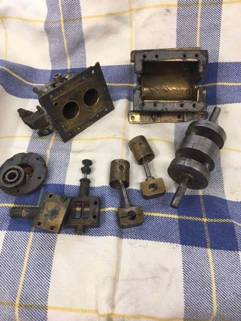
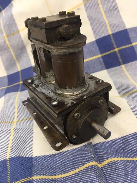
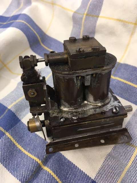
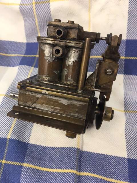
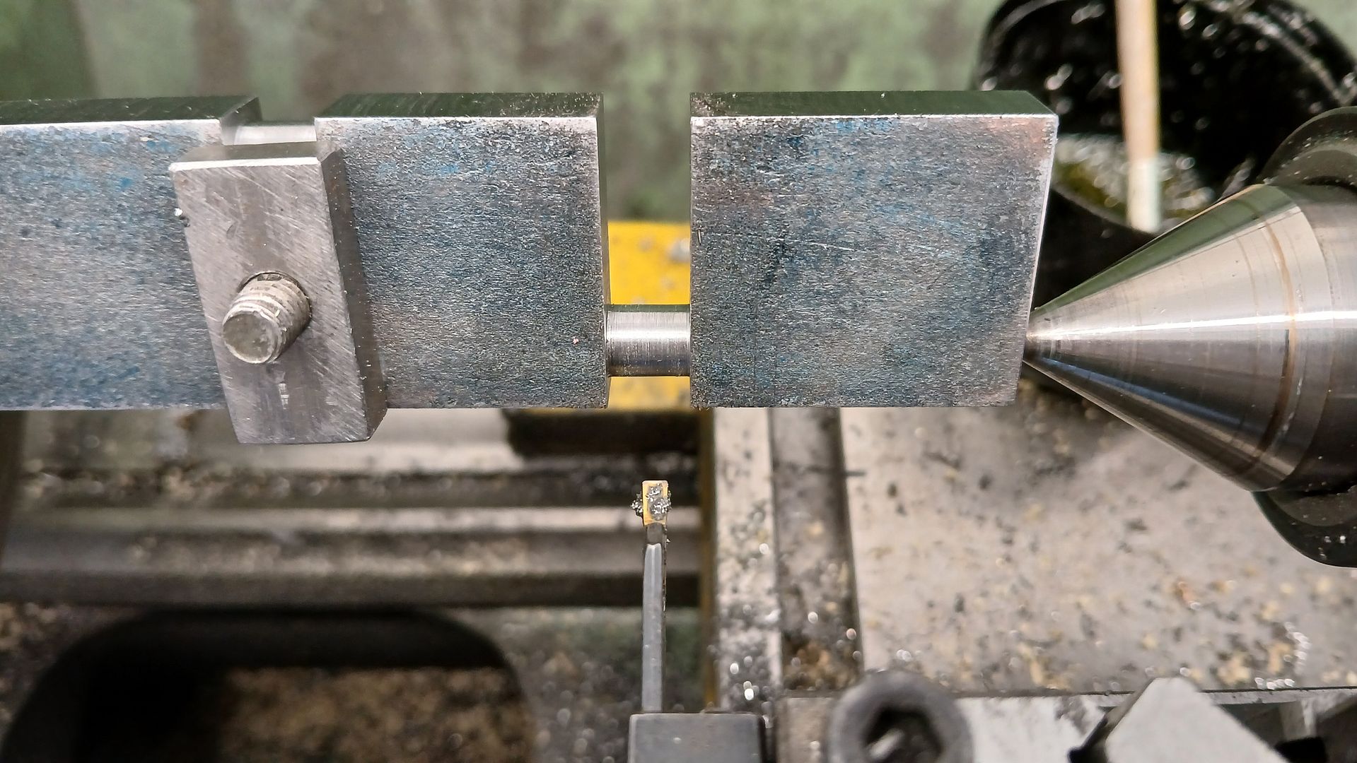
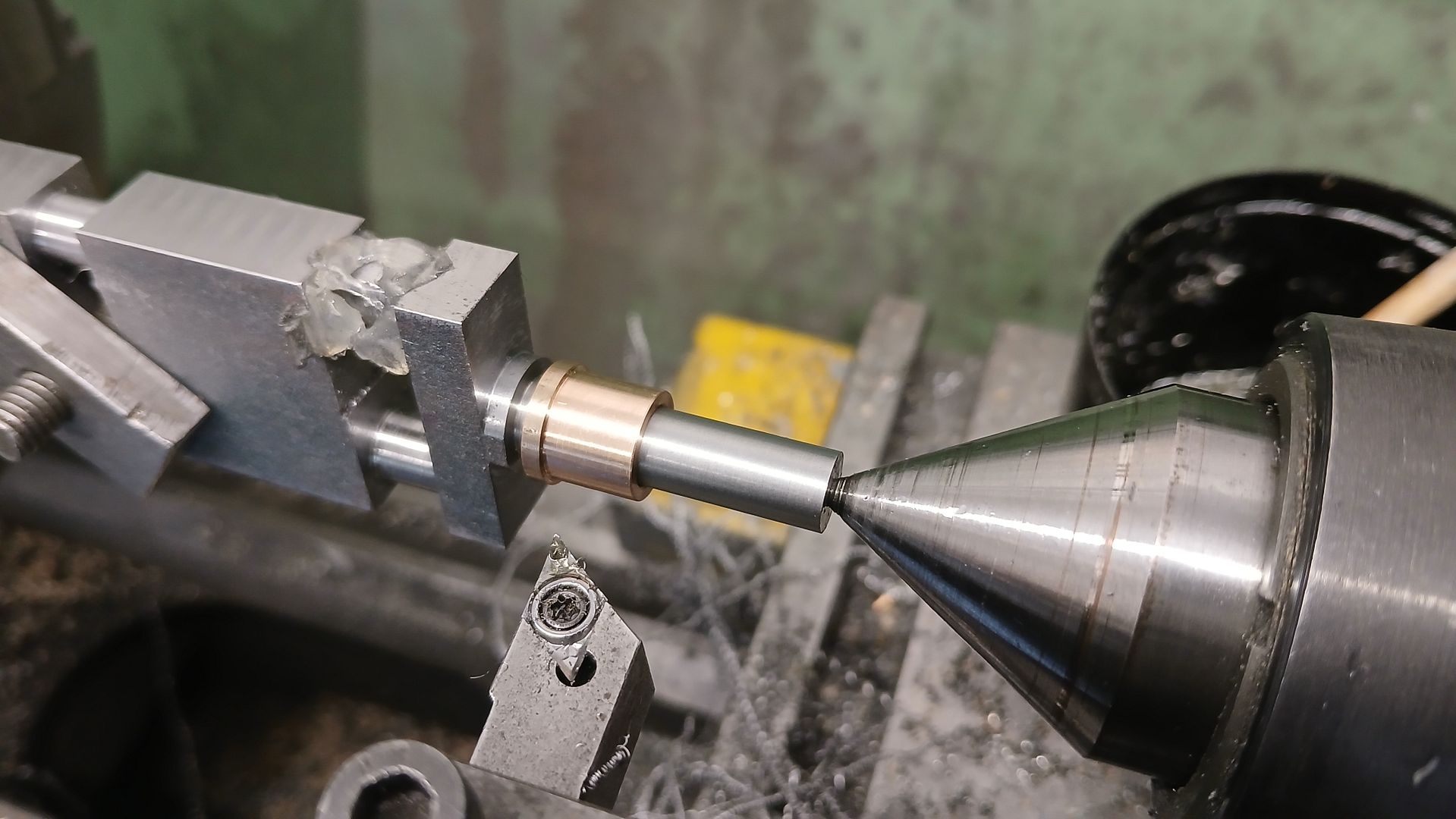
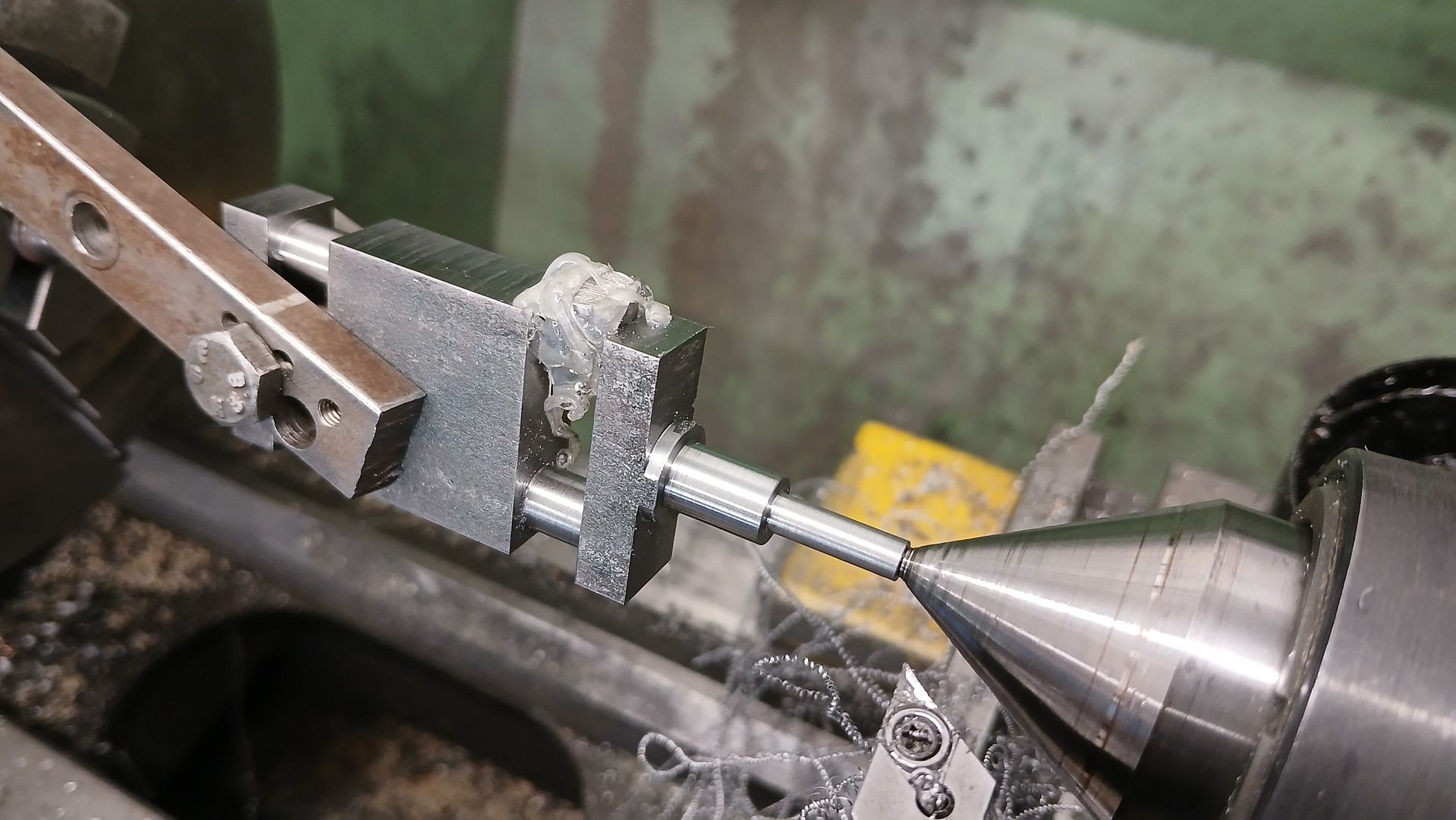
Stuart? MTB 1M
1
2
Started by:
JasonB
in: Stationary engines
- 9
-
17 June 2025 at 18:13
JasonB
-
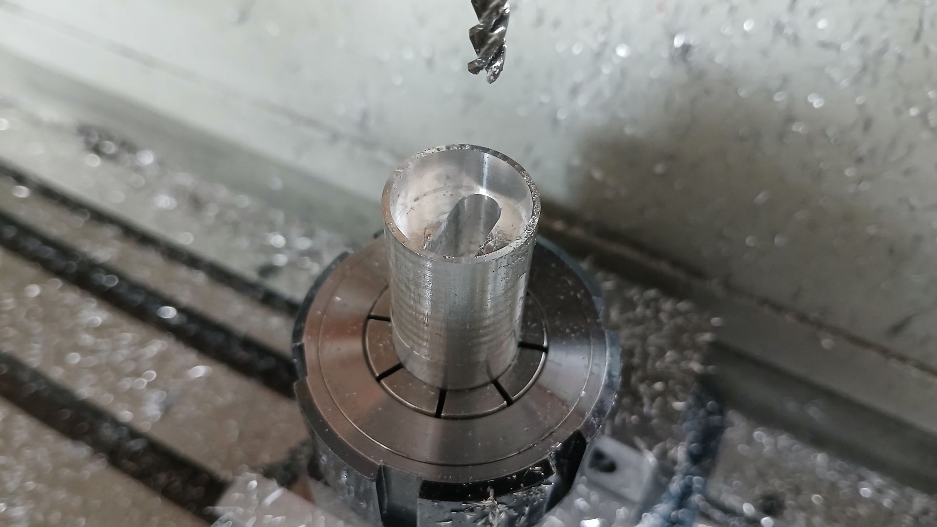
Setting the top slide to turn a Morse taper
Started by:
John Purdy
in: Workshop Tools and Tooling
- 10
-
17 June 2025 at 18:13
renardiere7
-
Micrometer ratchet springs
Started by:
Grindstone Cowboy
in: General Questions
- 9
-
17 June 2025 at 16:46
jaCK Hobson
-
Anybody with a Meddings Driltru bench drill or similar?
Started by:
Craig Brown
in: Manual machine tools
- 4
-
17 June 2025 at 15:55
John Hinkley
-
Small cutter feeds
Started by:
Dave S
in: CNC machines, Home builds, Conversions, ELS, automation, software, etc tools
- 4
-
17 June 2025 at 15:52
JasonB
-
Milling in the lathe – Vertical slide
Started by:
Chris12
in: Beginners questions
- 10
-
17 June 2025 at 15:38
Howard Lewis
-
How many rings per piston?
1
2
Started by:
Arthur Jones 2
in: Locomotives
- 14
-
17 June 2025 at 09:12
bernard towers
-
Steve 2250, new forum member
Started by:
steve2250
in: Introduce Yourself – New members start here!
- 3
-
17 June 2025 at 06:27
Howard Lewis
-
Meddings MF4 Manual
Started by:
Richard Kirkman 1
in: Help and Assistance! (Offered or Wanted)
- 5
-
16 June 2025 at 20:47
Michael Gilligan
-
Farm Boy
1
2
3
4
Started by:
Dalboy
in: I/C Engines
- 15
-
16 June 2025 at 17:09
Dalboy
-
Twin Engineering’s heavy mill/drill quill removal
Started by:
Martin of Wick
in: Manual machine tools
- 4
-
16 June 2025 at 15:51
bernard towers
-
Magnetic bases – stored on or off?
1
2
Started by:
Grindstone Cowboy
in: Beginners questions
- 25
-
16 June 2025 at 12:25
Robert Atkinson 2
-
Test Thread for inserting images
1
2
3
4
Started by:
JasonB
in: New Forum Software questions, comments and Test Threads
- 32
-
16 June 2025 at 09:19
jamesp1
-
PicPet
Started by:
duncan webster 1
in: Electronics in the Workshop
- 4
-
15 June 2025 at 20:46
John Haine
-
What Did You Do Today 2025
1
2
…
5
6
Started by:
JasonB
in: The Tea Room
- 32
-
15 June 2025 at 18:39
SillyOldDuffer
-
Bending Rolls
1
2
Started by:
Baldric
in: Workshop Tools and Tooling
- 15
-
15 June 2025 at 17:52
Baldric
-
The Sunday bazar
1
2
Started by:
Sonic Escape
in: The Tea Room
- 19
-
15 June 2025 at 17:40
Sonic Escape
-
Making form relived cutters
Started by:
Dave S
in: CNC machines, Home builds, Conversions, ELS, automation, software, etc tools
- 7
-
15 June 2025 at 13:59
Julie Ann
-
Metric Build
Started by:
danieldlonsdale@gmail.com
in: Traction engines
- 4
-
14 June 2025 at 23:36
Nigel Graham 2
-
A modern mystery (Yanmar injectors)
Started by:
Fulmen
in: The Tea Room
- 7
-
14 June 2025 at 22:42
Fulmen
-
Forum search


