Enlighten you? I don't know – possibly add to your confusion. For the sake of what follows, can I assume you have a copy of the Spindles book and that you're a beginner, with little engineering knowledge? It's safer not to assume knowledge sometimes.
I've just rooted out my copy of the book and am very surprised. The author does not discuss bearings in any detail and most of his designs are faulty. OK, they will almost certainly 'work', but they can be much better and at the same time simplified: bearing 'slack' can be minimized by simple re-thinking. You really shouldn't have to tolerate any avoidable free movement that can be designed out, and it's particularly important to avoid it in a spindle intended for milling, grinding, etc.
The problem is that the type of ball bearing used in most of his spindles are 'deep groove' ball bearings. These always have a tiny amount of radial clearance built-in. Clearance may be designed into the bearing to allow for expansion when whatever the bearing is fitted to heats up. Hot-running and high-speed bearings are designed slacker. Bearings come in different clearance grades. These are numbered, typically, C1 – C5, tighter being lower numbers, and more expensive. I haven't seen C1 grade available in 'our' sizes, from usual suppliers. CN is 'normal' clearance and is somewhere between C2 and C3. Aftermarket bearings are often C3 grade, to suit a wide range of hopefully-not-very-critical applications. CM is also somewhere between C2 and C3, and is supposed to be designed for electric motors, where quietness in operation is desired, so very smooth tracks, for low vibration, but I don't think 'tightness' is a design priority.
If you shake a typical C3 bearing set, with seals and all lubricant removed (bad for the bearing!), it will rattle surprisingly, and the inner track can be felt to move, in all directions, with respect to the outer. Figures for radial clearance can be found, buried in the manufacturers' data sheets, but axial clearance is rarely listed (as far as I can recall).
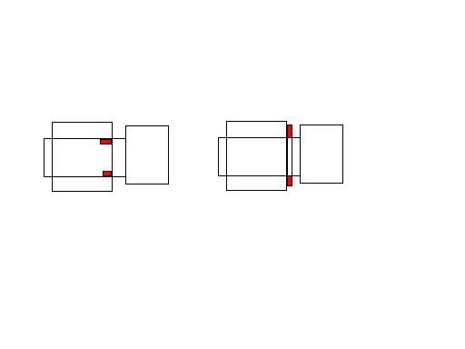
As the inner track is pushed axially into the outer track, the balls roll 'up the sides of the grooves' a little, and can thus react the applied axial force. This loading has removed the slack, and you'll note that the radial slack has gone, too. High radial forces can still, of course, cause the built-in radial slack to reveal itself, but, as axial force is increased, radial stiffness does also. What we want is to load each bearing in opposite axial directions, so the slack is taken up in each bearing. This is known as 'preloading', and is often done by adopting a mounting like the book's author does for his taper roller spindle: the outer tracks are prevented from moving deeper into the housing by shoulders, and the inner tracks are GENTLY pushed together by the nut at the pulley end.
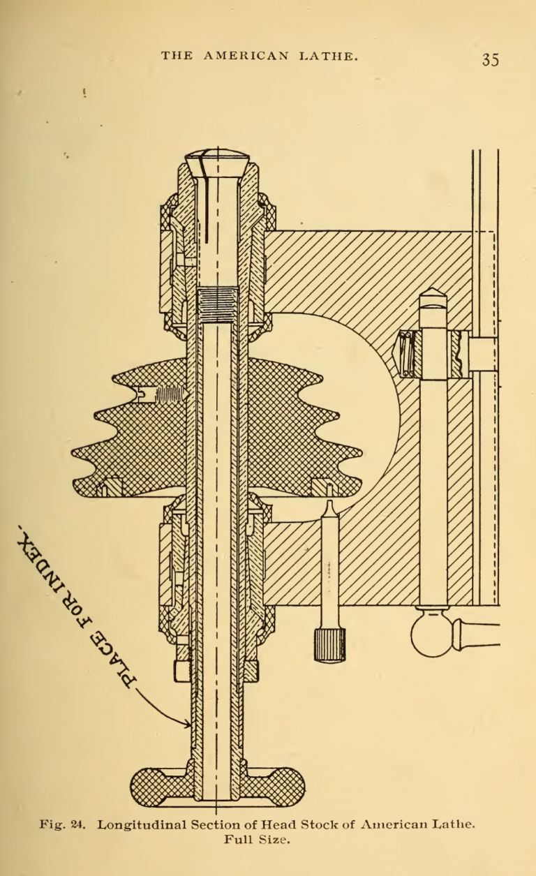
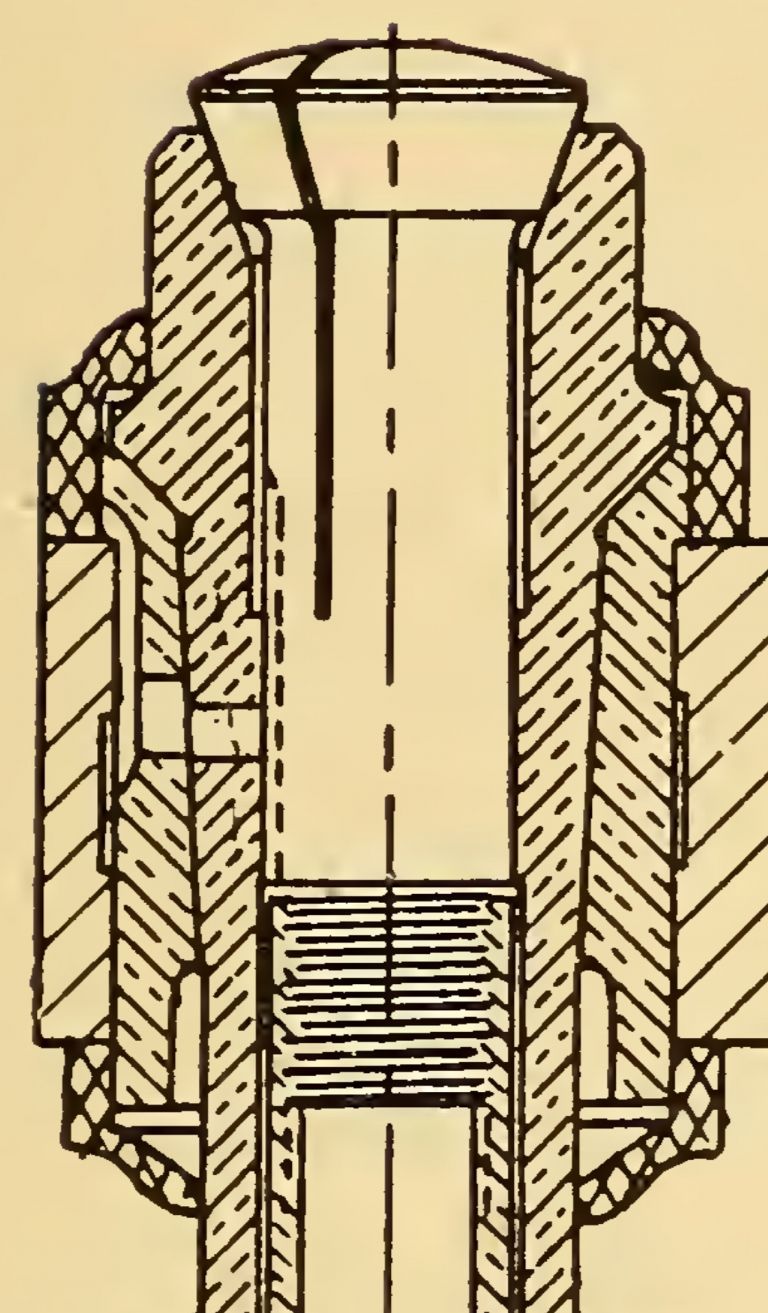
All this is absolutely standard stuff, and I'm disappointed that the book got published, containing as it does so many poor designs. The Ch5 design allows the cutter in the chuck to 'see' all the slack in the bearing nearest to it: preload is impossible. The Ch6, 7, 8, and 11 designs are bad: the only thing holding the spindle into the housing is the friction fit of the outer tracks of the bearings (and the rear one should be free to slide with a bit of effort). The spindle might easily vibrate out of its housing under the influence of milling vibration, until the outer track of the rear bearing abuts the shoulder in the housing. Also, again, no preload provision. The Ch9 &10 designs have no provision for adjustable preload – both inner and outer tracks of both bearings are fully constrained – so incredible precision of manufacture would be needed for real success.
The design in Ch 13 is fine, and also the simplest. It embodies what I've been trying to explain, albeit with taper roller bearings. Note that the inner tracks are constrained at their outer face only – there is no spacer tube between them, so they can be moved together by tightening the nut outboard of the pulley. The outer tracks are constrained at their inner faces by the shouldered housing. If deep groove ball bearings (or angular contact bearings – but that's another subject…) are substituted into this style of design, you have a design in which bearing clearance can be miminized. You can also go for C2 bearings, if you can source them (I can't, in NZ).
Someone may post that I'm being over-fussy, but the 'proper' design I've described is the easiest to make and employs the bearings to their best advantage. Hope this is enlightening, rather than baffling…
ega.


