Simple(st) boring head?

Advert

Simple(st) boring head?

Home Forums Workshop Tools and Tooling Simple(st) boring head?

Viewing 11 posts - 1 through 11 (of 11 total)
  • Author
    Posts
  • #17189
    Muzzer
    Participant
      @muzzer

      A simple, rugged, adjustable boring bar head for the milling machine

      Advert
      #132236
      Muzzer
      Participant
        @muzzer

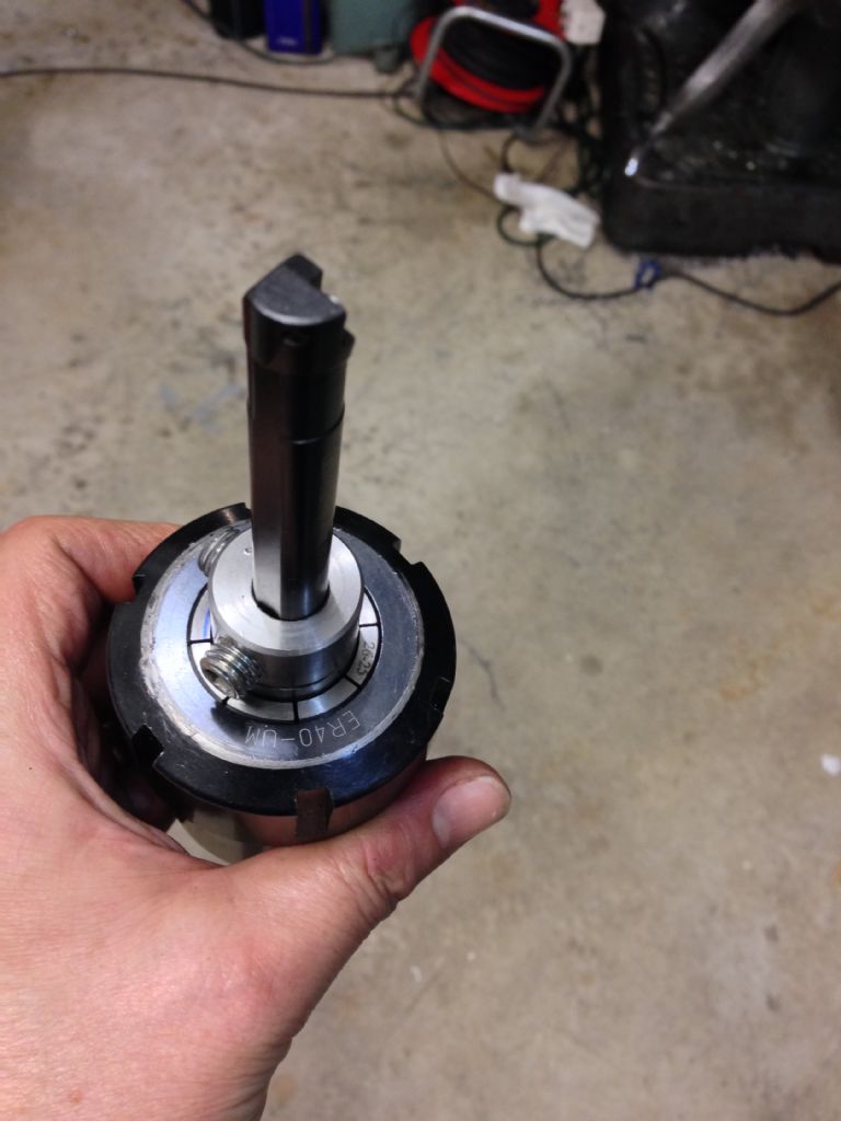
        Here's a simple boring head I've just made up for machining some 19mm bores into a steel D1-3 spindle nose body. If I manage to complete the machining process without any outrageous errors, I will end up with a base that accepts my various lathe chucks and faceplate and will bolt down to the milling machine table or rotary table.

        You'll probably look at this and think it's not a boring head at all, just a boring bar holder. However, due to the offset of the cutting edge relative to the axis of the bar itself and due to the eccentric hole it fits in to, it is actually an adjustable boring bar head requiring minimal effort to make – my kind of tool!

        I have 2 Glanze indeable boring bars that take the CCMT 6mm inserts that are also used in my lathe tooling. These are 12mm shank (6mm radius, then) and have a cutting edge that is 9mm from the central axis. Mounting this directly in a collet chuck will result in a hole of around 18mm diameter. However, as we know, it is possible to bore a smaller hole with these boring bars by bringing the tool off axis, eg in a common lathe useage. Glanze claim a minimum achievable bore diameter of 16mm but in fact you might arguably be able to get down nearer 15mm (6mm shank radius plus 9mm to the cutter edge), if you are not worried about maintaining much of a clearance to the tool in the bore.

        Mounting the bar in an eccentric 12mm hole drilled into a piece of round bar would allow the head of the bar to be rotated relative to the offset angle and thus give an infinitely adjustable cutting edge offset between 2 extremes. With the above mentioned tool and an offset of 1.5mm, a nominal hole size range of 15 – 21mm should be possible, on the face of it. Obviously any error in how parallel and straight the bar and hole are will affect those numbers.

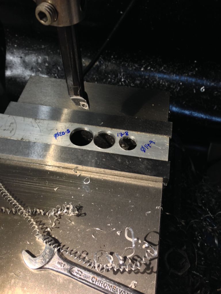
        I took a 3" length of 1" ground stainless bar I took from the ark(!) and drilled a 12mm hole through at a 1.5mm offset, using a slot drill for the first 35mm of the final pass, then drilled and tapped 2 x M10 threads radially into the end for retaining grub screws. With this in my ER40 collet chuck, I did some trial holes into some loominum, then some steel – a 14mm drill followed by passes at the min, mid and max positions. These measured at 14.9, 17.8 and 20.5mm. Not bad.

        With this arrangement, when the tool is at the max or min position, the insert is presented to the work at the default recommended angle (several degrees below horizontal). However, somewhere not far from the midpoint, the cutting edge reaches a maximum angle of around 6 degrees further below the horizontal. However, the effects at the cutting edge should be second order, as the tool will be mostly cutting axially, not radially, assuming a reasonable depth of cut relative to the tip radius.

        My aim with this was to maximise the rigidity of the setup without simply blowing loads of dosh on "proper" tools and to me it looks as if this is about as simple and robust as you can get. The proof of the pudding will be when I attempt the full 30mm depth of the 19mm bore into steel for real (3 times!). I'm sure this isn't a novel technique but it's not something I've personally encountered before.

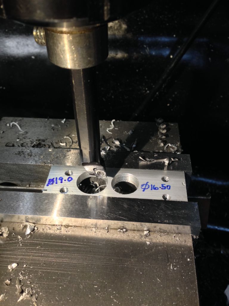
        I also made up a second version that had a smaller, 1mm offset that gave an adjustment range of 16.5 – 19mm, much as you might expect. This would allow finer control of the depth of cut due to adjustments of the angle. For my 19mm holes, that might be the better choice, starting with a 16.5mm drill.

        Merry

        1mm offset bar.jpg

        1mm offset results.jpg

        1.5mm offset results.jpg

        #132271
        Michael Gilligan
        Participant
          @michaelgilligan61133

          Looks very useful, Muzzer

          … Suitably rigid for those deep, small bore, holes.

          My only concern is; how do you set it to a specific diameter ?

          Conventional Boring Heads are calibrated: This one looks like it will all be "cut & try"

          MichaelG.

          #132281
          jason udall
          Participant
            @jasonudall57142

            Calibration of a sort could be done…..a set of nonlinear markes round base and add index mark on holder ( er collet in this case..but even that could be home made)

            #132294
            Thor 🇳🇴
            Participant
              @thor

              Neat idea Muzzer, if I didn't already had a boring head I would try your solution.

              Thor

              #132297
              Sub Mandrel
              Participant
                @submandrel

                Nice bit of lateral thinking. Could that be developed into a short write up for MEW?

                Neil

                #132322
                Muzzer
                Participant
                  @muzzer

                  Yes, the problem is fine adjustment. Without complicating it too much, I can only think of a vernier scale by way of practical adjustment, but that's not going to happen.

                  What I did in the end was to plot the variation of the final diameter against the angle of the bar relative to the carrier. By entering the actual max and min measured, I can scale the curve to what I actually have rather than I might theoretically have ended up with, as I can infer both the eccentricity and the offset fairly closely. Then, after boring and measuring an undersize trial hole, I was able to estimate the angular correction required. Setting that angle was the tricky bit obviously, but it's easier to implement a small correction than to get a large angle spot on.

                  12mm glanze with 1.4mm eccentricity 20131010.jpg

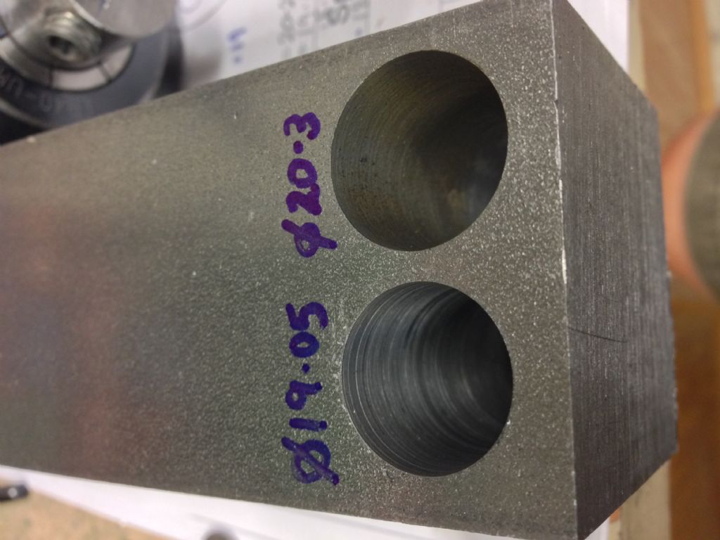
                  Obviously it took me a couple of goes to get there but in the process I was able to have a go at boring some real holes of increasing diameter in a piece of 2" steel square section. I seen worse but it's clear that a deeper cut (top) gives a cleaner finish, so I won't try to creep up on it too slowly. Given that I'm looking to bore a 19mm hole, I'll leave it where it is. Fortunately, I have 2 boring bars and 2 eccentric holders now, so I can use the other one to perform the one or two roughing cuts and then swap them over for the finish. Well, that's the plan at any rate.

                  Trial holes

                  Muzzer

                  #132326
                  Michael Gilligan
                  Participant
                    @michaelgilligan61133

                    Sounds like a good plan.

                    MichaelG.

                    #132358
                    jason udall
                    Participant
                      @jasonudall57142

                      12mm glanze with 1.4mm eccentricity 20131010.jpg

                      nice looks like

                      D = -(8.85+2*1,4)(sin(thea)} +2*8.85


                      Edited By jason udall on 11/10/2013 11:34:23

                      #132414
                      Muzzer
                      Participant
                        @muzzer

                        Pretty much:

                        = 2*($C$2-$C$3*SIN(RADIANS($B6))), where

                        Offset (C2) 8.85
                        Eccentricity (C3) 1.4

                        …and B6 is angle (degrees!)

                        #132513
                        Muzzer
                        Participant
                          @muzzer

                          I'm pleased to report that I've now machined my 3 radial bores and they came out at exactly 19mm rather than the 19.1 I'd expected. I ended up making 3 passes with the final setting. Presumably the bar still springs enough to be noticeable but then it's only a 12mm one and there's a fair bit of overhang. Feed was 3 thou/rev and speed about 400-600 depending on the heaviness of the cut.

                          Bottom line – I tried one of the cams from my Bantam spindle nose and it fitted rather nicely (this part is the main body of a D1-3 spindle nose that bolts to a machine table). Given the way the different bores break through into each other, the result was pretty good, with no obvious changes of finish or signs of chatter. It was a bit of a pig to debur but I seem to have managed it now.

                          The thing looks remarkably like the CAD model except for a 1 degree discrepancy between the actual and planned positions of the cam bores due to poor setup obviously. It means that as it stands I can't insert the chuck pins with the cams in place. Luckily the angular error was in the "right" direction, so I can elongate the holes for the chuck pins to compensate and it will function as intended.

                          After an hour or so of measurement and setup, I'm ready to have a go at this tomorrow. Reboring the 15mm hole about 0.6mm from where it is should be another test of the bar and my own skills. Things could go horribly wrong! Then the final challenge will be to make up 3 eccentric cams to complete the spindle nose.

                          I'd post a photo but the "edit photos" link isn't being very helpful unless you are looking for "page not found".

                          Muzzer

                        Viewing 11 posts - 1 through 11 (of 11 total)
                        • Please log in to reply to this topic. Registering is free and easy using the links on the menu at the top of this page.

                        Advert

                        Latest Replies

                        Viewing 25 topics - 1 through 25 (of 25 total)
                        Viewing 25 topics - 1 through 25 (of 25 total)

                        View full reply list.

                        Advert

                        Newsletter Sign-up