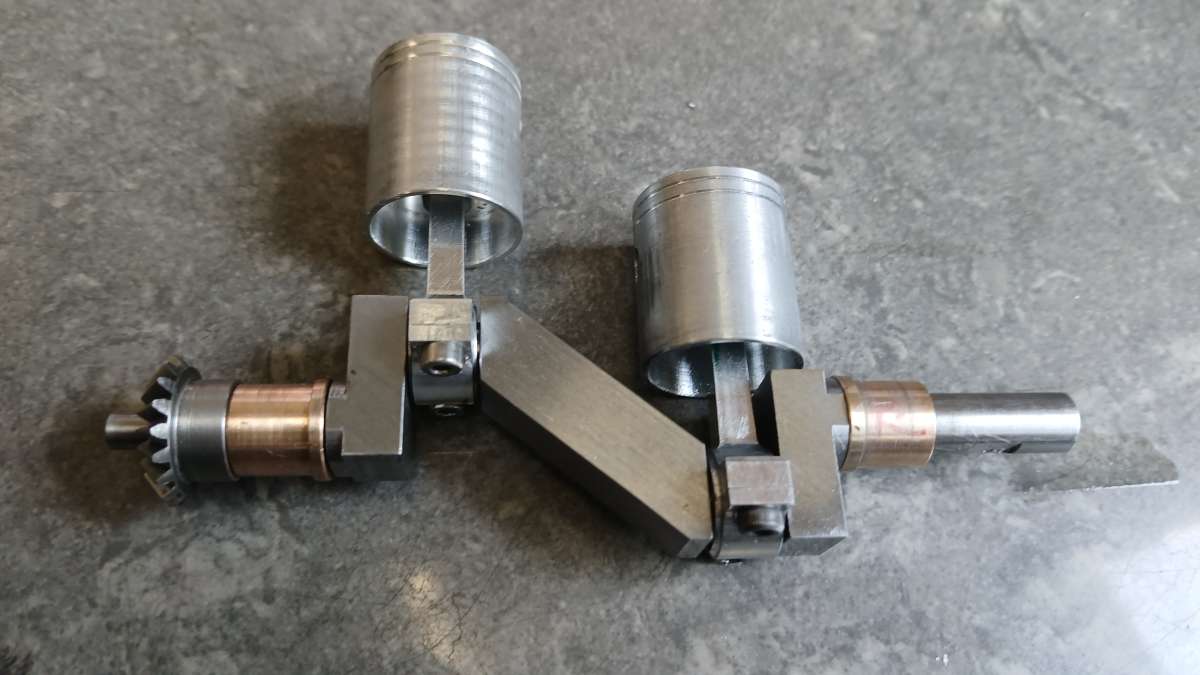
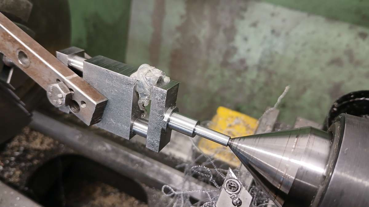
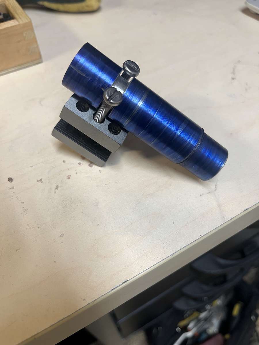
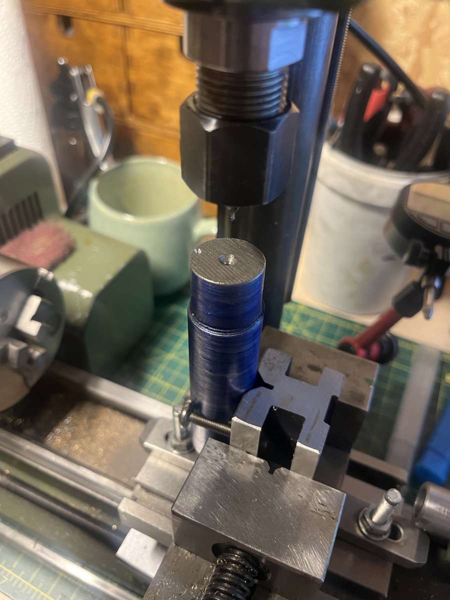
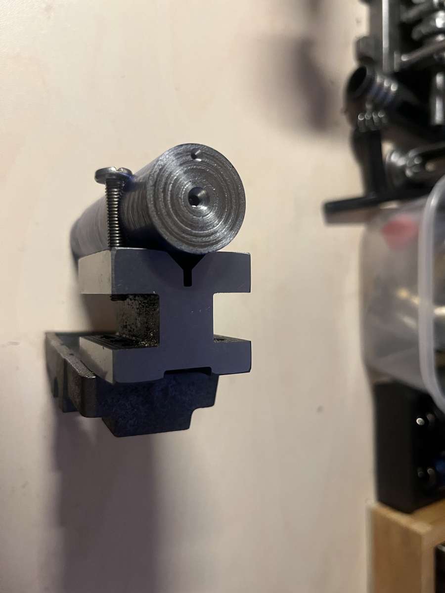
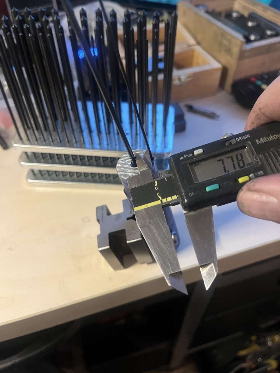
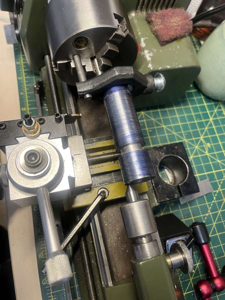
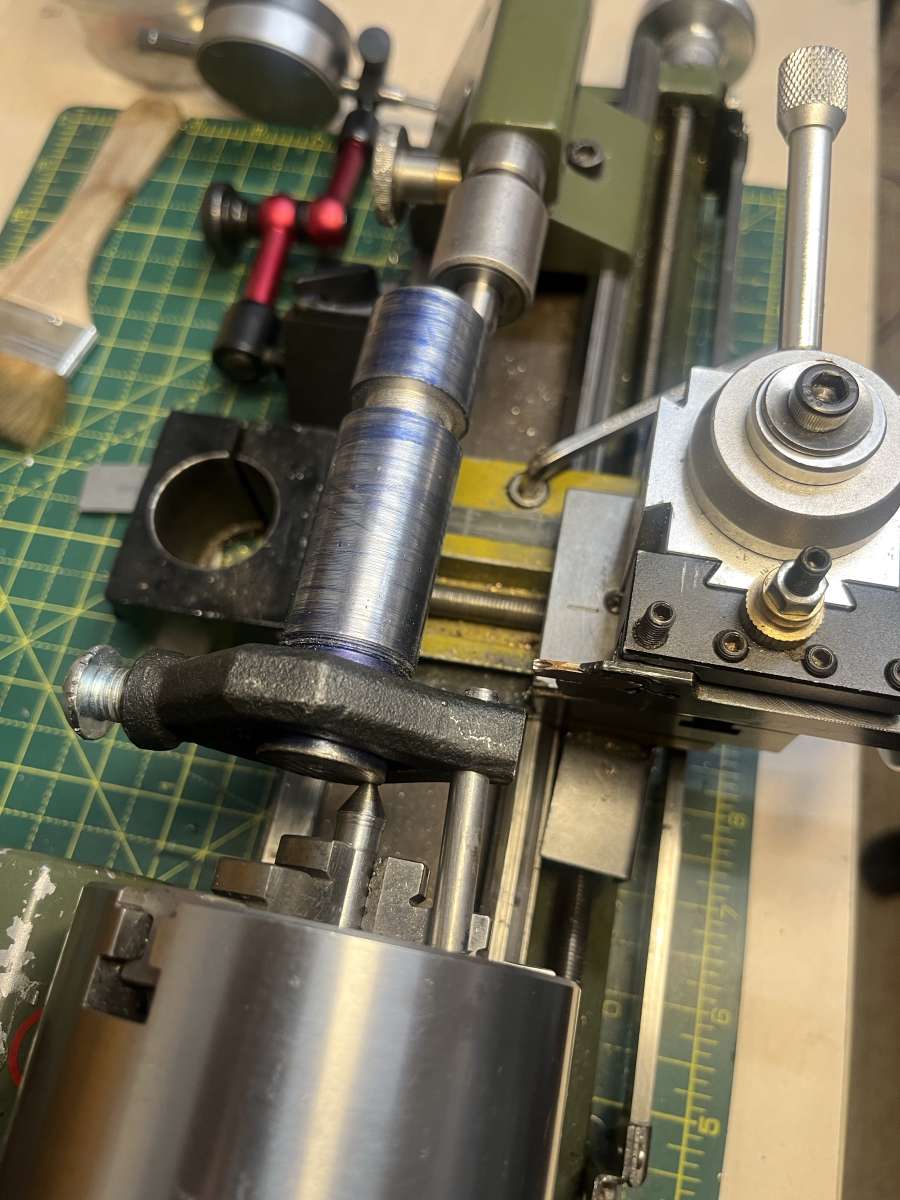
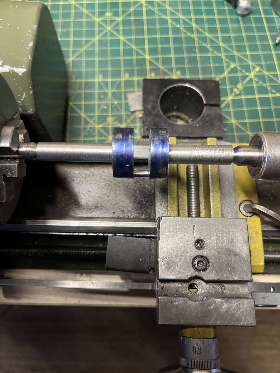
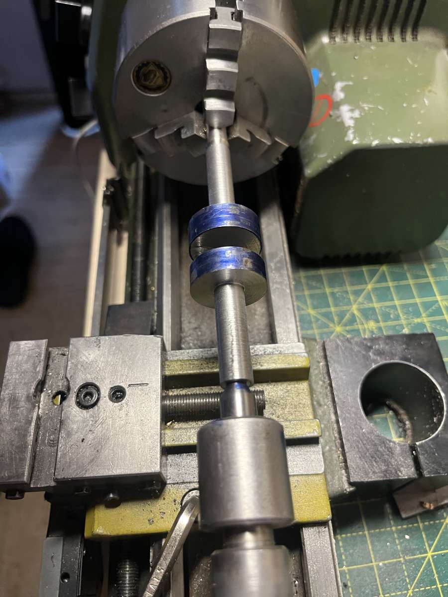
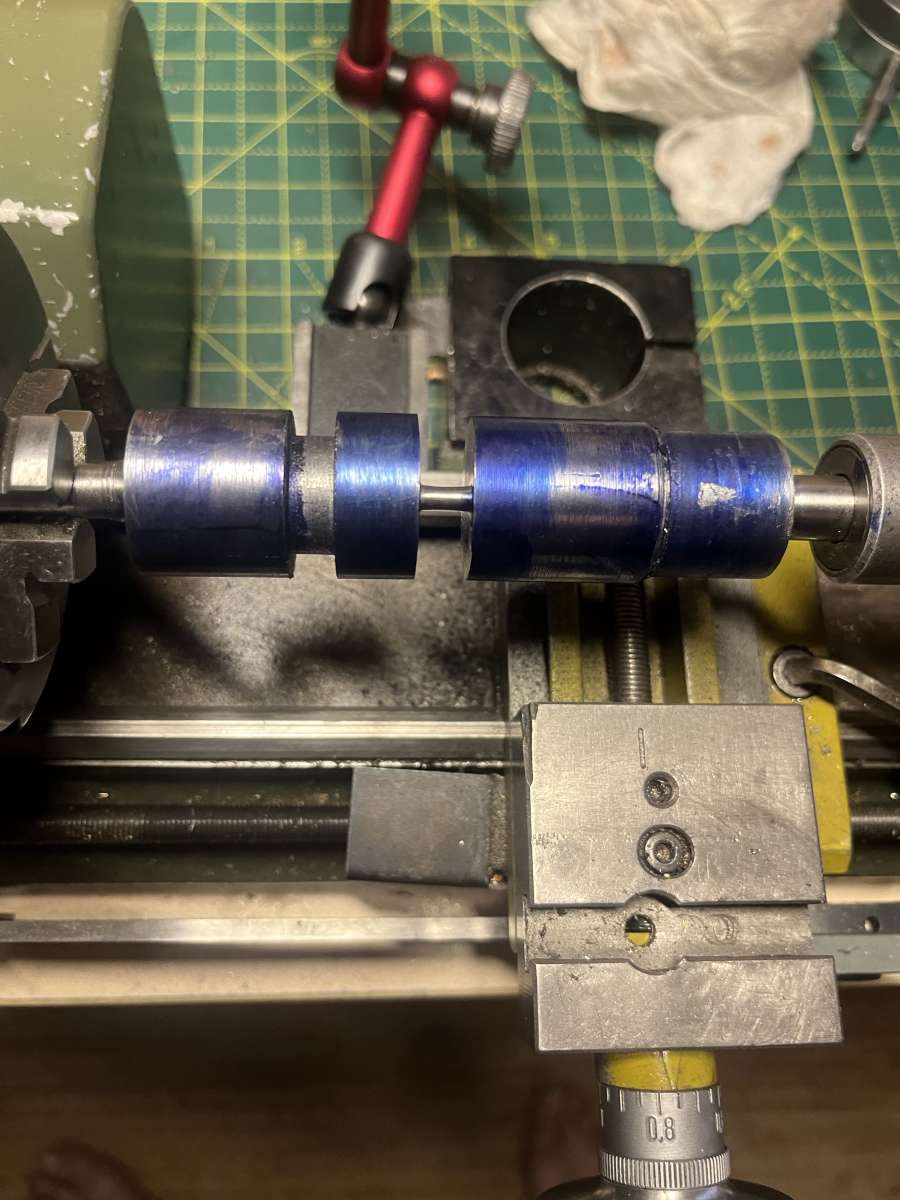
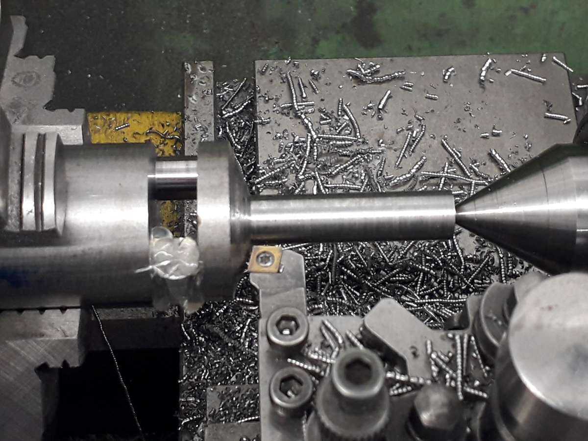
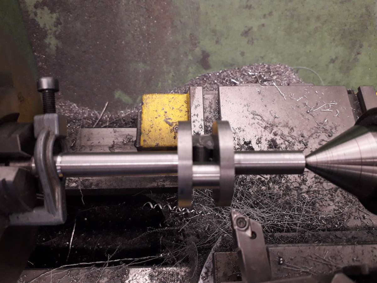
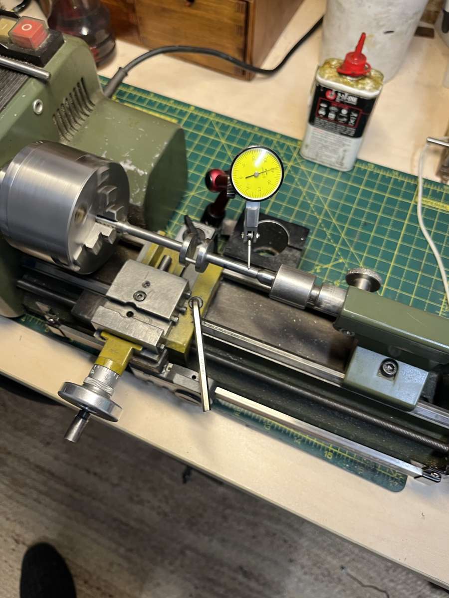
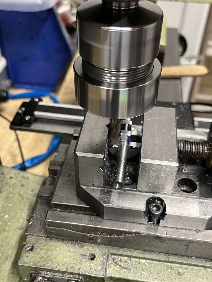
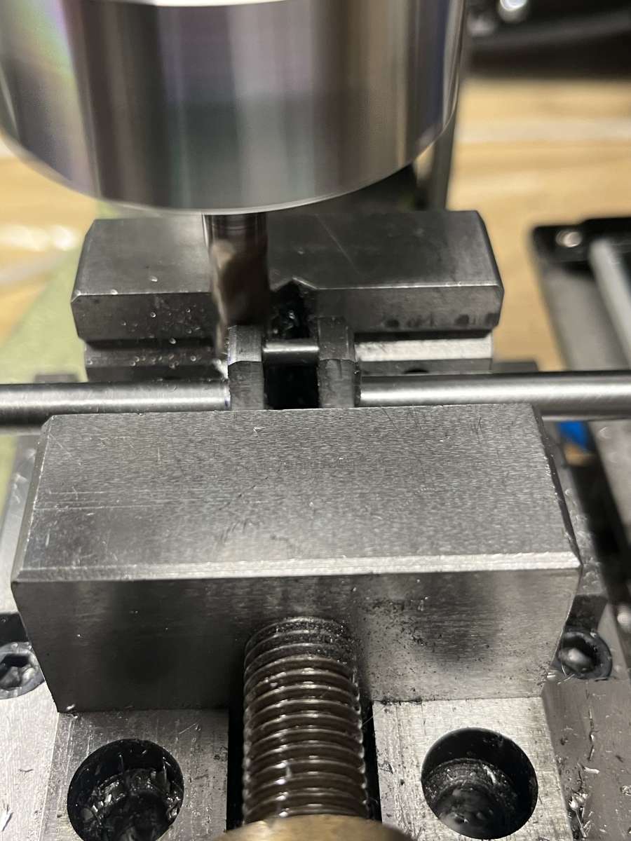
Silver steel crankshaft
Silver steel crankshaft
- This topic has 37 replies, 11 voices, and was last updated 17 July 2025 at 11:49 by
 cogdobbler.
- Please log in to reply to this topic. Registering is free and easy using the links on the menu at the top of this page.
Latest Replies
-
- Topic
- Voices
- Last Post
-
-
Meek style dog-clutch for a Colchester
Started by:
Taris Jewell
in: Manual machine tools
- 2
-
4 August 2025 at 00:50
Clive Foster
-
Chuck- Lathe yet another type.
Started by:
Speedy Builder5
in: Workshop Tools and Tooling
- 7
-
3 August 2025 at 23:45
Nicholas Farr
-
Help recommend a milling machine?
Started by:
richard1989
in: Beginners questions
- 16
-
3 August 2025 at 22:55
Vic
-
Why am I confused?
Started by:
JimmieS
in: The Tea Room
- 7
-
3 August 2025 at 21:55
Harry Wilkes
-
Depth of cut cowells me90
Started by:
kinross1
in: Manual machine tools
- 7
-
3 August 2025 at 20:29
JasonB
-
Beginner with newly bought lathe – many questions
1
2
Started by:
ell81
in: Beginners questions
- 16
-
3 August 2025 at 20:17
peterrivers
-
New member – mid 50s Zyto Lathe
Started by:
peterrivers
in: Introduce Yourself – New members start here!
- 1
-
3 August 2025 at 20:14
peterrivers
-
What Did You Do Today 2025
1
2
…
8
9
Started by:
JasonB
in: The Tea Room
- 34
-
3 August 2025 at 20:07
Diogenes
-
Paint stripper does not do what it says on the tin
Started by:
Greensands
in: Hints And Tips for model engineers
- 11
-
3 August 2025 at 20:00
old mart
-
Turning a small radius corner
Started by:
Richard Brickwood
in: Workshop Techniques
- 4
-
3 August 2025 at 19:13
duncan webster 1
-
How to balance a cup grinding wheel
Started by:
Clive B
in: Workshop Tools and Tooling
- 9
-
3 August 2025 at 18:06
David George 1
-
Expansion links
Started by:
Chris West 1
in: Hints And Tips for model engineers
- 3
-
3 August 2025 at 17:49
Speedy Builder5
-
WELL WORTH A READ
Started by:
Speedy Builder5
in: Workshop Techniques
- 2
-
3 August 2025 at 17:23
Speedy Builder5
-
MD65 leadscrew cross-slide stuck in nut
Started by:
leov
in: Manual machine tools
- 5
-
3 August 2025 at 16:49
Martin Kyte
-
Seig SX3.5ZP
Started by:
IanT
in: Manual machine tools
- 8
-
3 August 2025 at 16:46
old mart
-
retirement aaargh!
Started by:
grimme
in: General Questions
- 19
-
3 August 2025 at 16:27
old mart
-
Arc Euro Trade Ltd.
1
2
3
Started by:
Ketan Swali
in: General Questions
- 50
-
3 August 2025 at 16:10
old mart
-
Pratt Bernard Grip true issues
Started by:
teamricky
in: Workshop Tools and Tooling
- 1
-
3 August 2025 at 16:09
teamricky
-
Cut knurling
Started by:
Fulmen
in: Workshop Tools and Tooling
- 13
-
3 August 2025 at 14:17
Wade Beatty
-
CNC Coolant
1
2
Started by:
Steve355
in: CNC machines, Home builds, Conversions, ELS, automation, software, etc tools
- 13
-
3 August 2025 at 14:13
Clive Foster
-
Alternatives for a DRO display change
Started by:
John Hinkley
in: General Questions
- 2
-
3 August 2025 at 13:46
John Hinkley
-
100mm 4 jaw chuck servicing
Started by:
John Millis
in: Workshop Tools and Tooling
- 5
-
3 August 2025 at 13:45
old mart
-
MIG Welder Won’t Weld
Started by:
Martyn Nutland 1
in: Workshop Techniques
- 13
-
3 August 2025 at 13:18
cogdobbler
-
Hi I’m a newcomer
Started by:
brumfan1991
in: Introduce Yourself – New members start here!
- 2
-
3 August 2025 at 13:12
bernard towers
-
Cutting thin slots in 12mm mild steel
Started by:
Peter Simpson 3
in: Beginners questions
- 9
-
2 August 2025 at 20:26
JasonB
-
Meek style dog-clutch for a Colchester
Latest Issue

Newsletter Sign-up
Latest Replies
- Meek style dog-clutch for a Colchester
- Chuck- Lathe yet another type.
- Help recommend a milling machine?
- Why am I confused?
- Depth of cut cowells me90
- Beginner with newly bought lathe – many questions
- New member – mid 50s Zyto Lathe
- What Did You Do Today 2025
- Paint stripper does not do what it says on the tin
- Turning a small radius corner

