Ian,
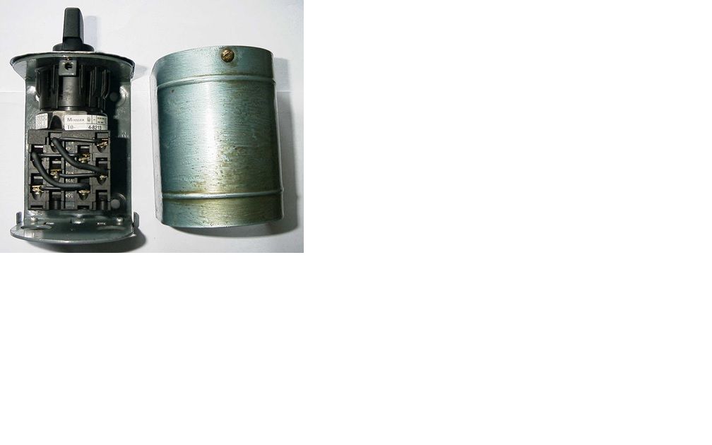
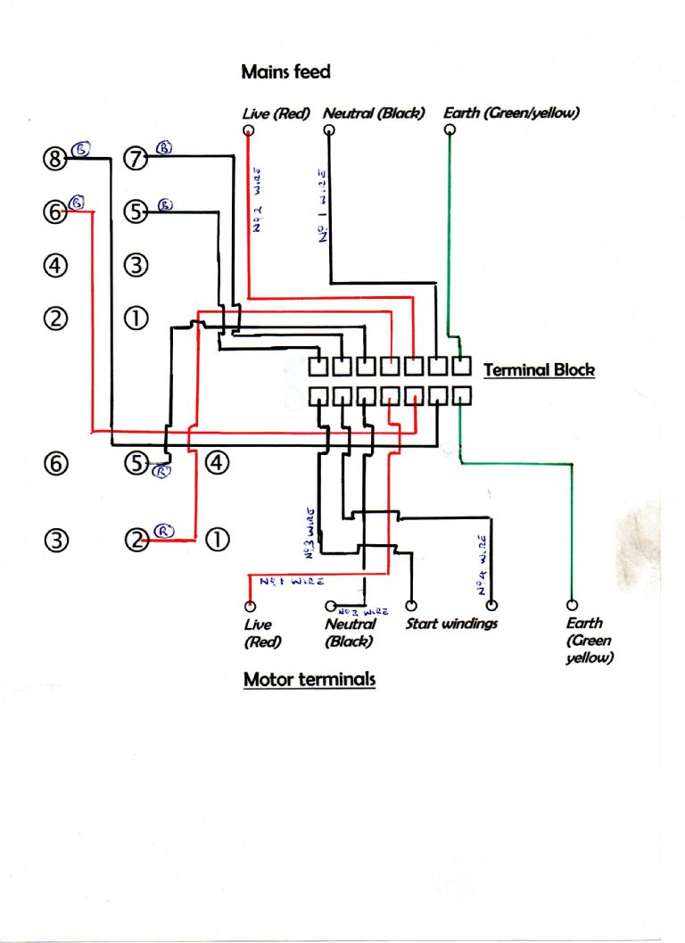
I'm just wiring up one of those Chester switches. The wiring as supplied is as shown in Jon's pic, (minus the terminal block) but in the latest iteration the wires are not all black. The mains input wires are the short black pair attached to terminals 6 and 8.
Be aware that throughout this switch, contrary to domestic wiring convention a red wire does not indicate "live" nor does black indicate "neutral".
The pair of red wires coming from the centre terminals of the rocker switch are one set (i.e. one is live and one is neutral) and are used on one of the two windings on the motor. Similarly the black wires coming out of terminals 7 and 5 are another set for the second winding.
I've used coloured tape to identify the various polarities as in the pic below.
26231873978_da9915166a_c.jpg
This is the rear of the rocker switch showing the pair of red leads that feed one of the windings on the motor.
40106234341_a5354d209c_b.jpg
To check which of these is the live or neutral, I first wired terminals 5 and 7 (the black pair) to a lamp. With your live mains input attached to terminal 8, terminal 7 is your live to the lamp. The lamp lit when I switched on. Then I removed the neutral and substituted on of the red leads. It didn't light up, so it must have been another live feed. Changed it for the other red, the lamp lit so I'd positively identified the neutral.
It all sounds complicated but when you study the switch unit it's pretty simple.
Two other things I'm going to do is make much better provision for earthing than the old Dewhurst did: there was no earth to the motor casing at all, just to the switch body, plus add in an emergency stop button.
Tried to embed the pics but the album function wasn't having it.
Hope this helps, Eug
Edited By Eugene on 05/02/2018 23:24:53
Edited By Eugene on 05/02/2018 23:29:52
Eugene.


