Thanks Chaps.
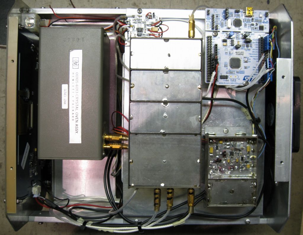
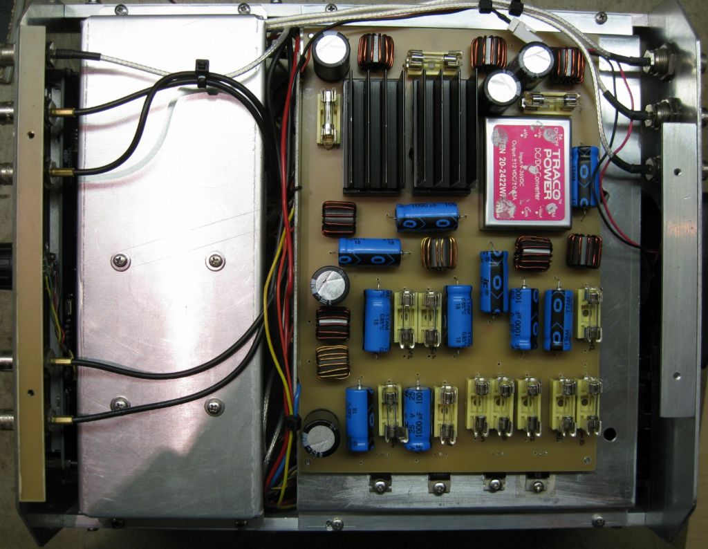
Dave, it was about a hundred hours of work, but took around 2 months. A lot of development work! The 5 to 10MHz doubler and subsequent amplifiers and splitters to generate 4 independent 10dBM 10MHz outputs took some doing to get clean signals, all harmonics better than -70dBc, etc.
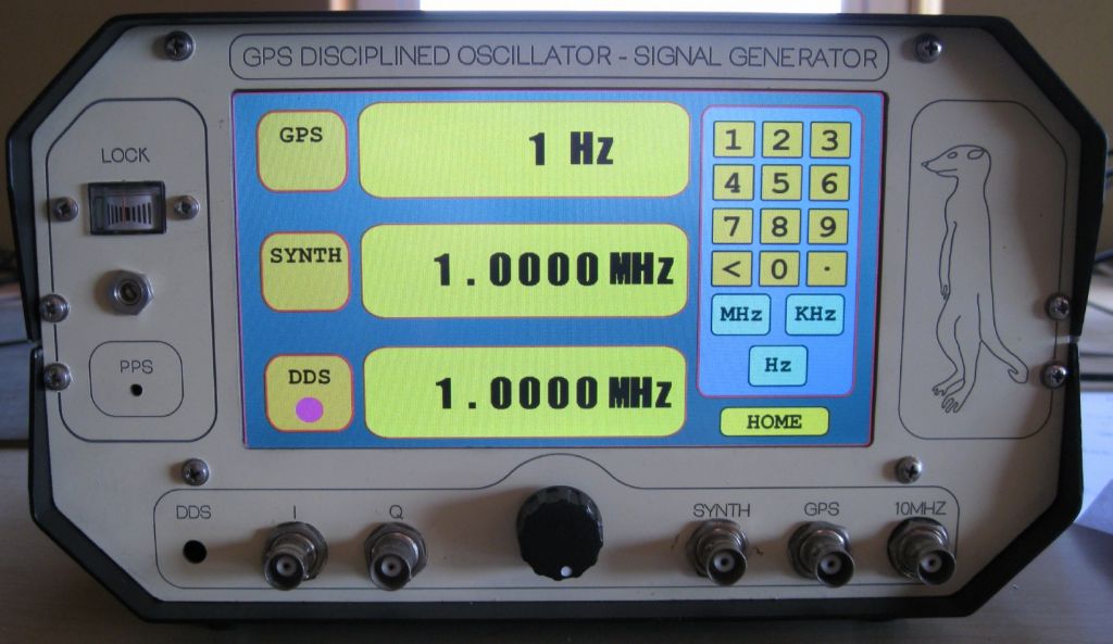
The signal gen and DDS outputs are also around 10dBM, but not so clean – quite adequate as a signal for , say, receiver alignment or diagnostics, but lots of strong harmonics. The PLL (Si5351) essentially generates a square wave output up to 200MHz. I only have 2 switched low-pass filters, one at 80MHz, one at 200MHz. Likewise the DDS has switched Lo-pass at 30MHz and at 60MHz.
Had to seriously filter the 26MHz from the Si5351 PPL to the GPS – a 12 pole Cauer low-pass – to make sure the GPS clock is good 'n clean..
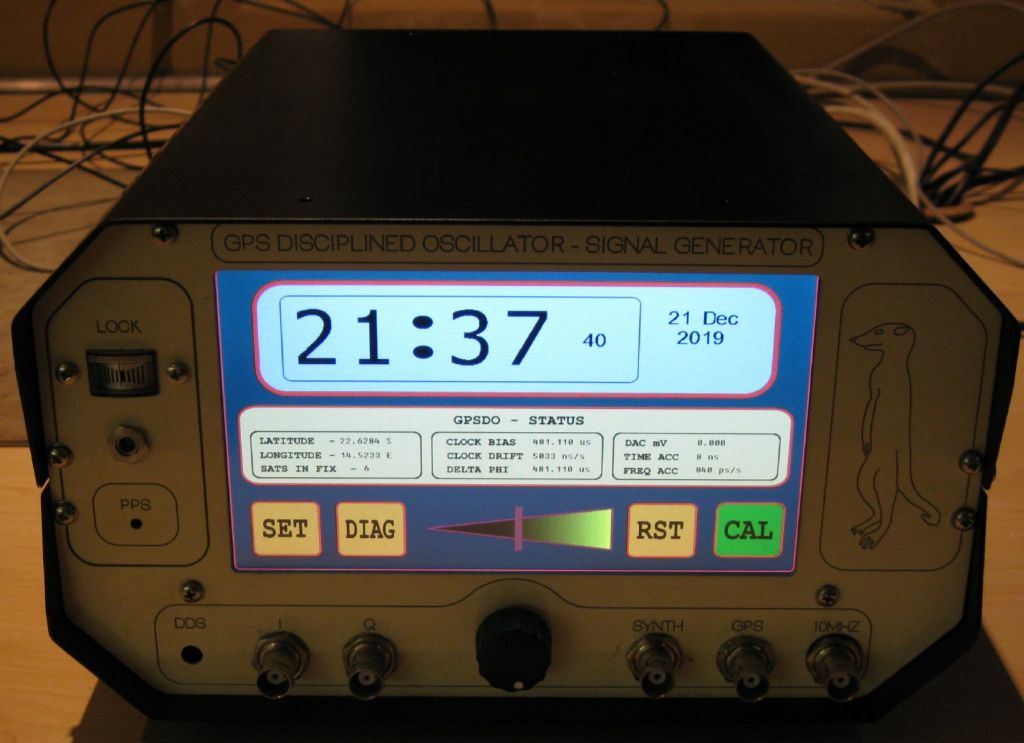
The display – a 7inch Nextion, is a treat – they are easy to use, and give a pro look to the unit – also, if you forget a switch or control in the front panel layout, you can just add it on the touch display! I use inkscape ( a freebie) to generate the imagery and transfer that to the display.
Interesting mind image that, Lions at the Dentist..
Robert –
Not sure I understand your question? I think you are asking why did I not just program the GPS Time Pulse output to output 10MHz? This gives a very accurate signal as well, since it is locked to the SAT reference, but unless you choose your GPS VERY carefully, you end up with signals that have very high jitter. You need to use a GPS intended for Time Pulse generation, and not all of those do it either. There were some GPS's ( the Jupiter, some 8 years old) that worked well this way and gave a stable, low jitter output, but that one is no longer available. The problem is that the GPS internal reference ( on most) is based on a 48MHz clock, and that does not divide down to 5 or 10MHz..the jitter on 10MHz is terrible, many 10's of ns. If you select say 8MHz, you get a jitter free signal ( well , a few ns.)
So, most 'good' GPSDO's use an external, low drift reference oscillator, and since most of these are not at the GPS module reference frequency, you 'multiply' the ref osc up to the required freq ( 26MHz in my case) via a PLL synth.
Then there are two typical ways to determine the frequency offset- Use the ref osc to also feed a counter whose gate is controlled by the 1PPs from the GPS module ( this can have a few 10's on ns jitter as well…)
If the counter overflows a set value, the clock is too fast, and vise versa. That over/underflow then is integrated and creates a control voltage that drives the ref osc up or down in frequency. The integrator must have a long time constant, etc.
A alternative way is to use the data the GPS provides in the NAV-CLOCK message – Clock Bias ( essentially the amount of TIME the GPS is ahead or behind the GPS SAT Time) and the Clock drift rate ( normally in us/s or ns/s)
If behind time, we speed the clock up by increasing the clock control voltage. The amount we increase the clock control voltage per GPS cycle is dependent on the clock drift rate – a high drift demands a bigger voltage jump in each cycle – almost an inherent PID control loop. The Loop is actually an FFT/filter with a 32 second cycle time.
I implemented both the above concepts, and found the latter improved the clock bias from 7ppb to 3ppb over a 4 day period..
Sorry, too long a story with nothing to do with 'engineering' as exercised on this forum! ( except for the metal bashed box.)
Joe
 Robert Atkinson 2.


