Myford S7 Cutting Barrel Shaped Cylinders

Advert

Myford S7 Cutting Barrel Shaped Cylinders

Home Forums Workshop Tools and Tooling Myford S7 Cutting Barrel Shaped Cylinders

Viewing 25 posts - 51 through 75 (of 114 total)
  • Author
    Posts
  • #476037
    SillyOldDuffer
    Moderator
      @sillyoldduffer
      Posted by Hopper on 30/05/2020 09:42:45:

      Posted by blowlamp on 29/05/2020 22:26:47:

      I'm wondering how worn or loose spindle bearings could move to allow both the near & the far end of a test-piece to be cut narrower than the middle portion. indecision

      Martin.

      My Myford had almost 15 thou of spindle movement when I got it.

      … Then add in bed wear moving the tool in another weird direction, both vertically and horizontally, plus wear on the carriage allowing carriage to pivot. Leadscrew alignment and halfnut adjustment can then get involved. And we havent even mentioned gib adjustment. It gets complicated, and weird. Anything can happen.

      You can't align a bed to a spindle that is flopping about all over the place like mine was. It's something that needs to be checked.

      Hopper makes a really good point when he says 'anything can happen'. Been up the garden path myself many a time due to misleading measurements.

      Struck me often since joining the forum that much lathe adjustment advice assumes the machine is in generally good order, for example levelling a lathe to remove bed twist assumes the ways are flat.

      Unfortunately a pre-loved machine might well have multiple problems : worn bed, floppy spindle bearings, loose gibs, wonky head and tailstocks etc. And in addition to wear and tear, the machine might have been bodged in the past by CoCo the Clown.

      I've never seen a comprehensive assessment guide explaining how to check an untrustworthy lathe for several faults. Faced with a well-used lathe in unknown condition where everything is suspect, how would the team go about making the machine fit for use again, and in what order should tests be made?

      Dave

      Advert
      #476039
      Hopper
      Participant
        @hopper

        See my recent articles in MEW on doing just that with the Myford.

        Pete Barker

        #476043
        Mike Donnerstag
        Participant
          @mikedonnerstag

          Apologies all – I'm struggling to keep up with all of the information, but I'm formulating a plan for today:

          • Check the spindle bearing play
          • Adjust the bearings
          • Take spindle nose measurements again, this time without belt tension (last time measured under tension)
          • Try turning between centres to eliminate the possibility of headstock misalignment
          • Test the concentricity of the test bar
          • Lay in the sun to recover and contemplate findings

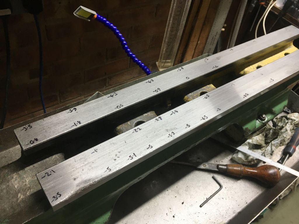
          Gray: below is a photo of the measurements showing the difference from the unworn end of the bed in thousands of an inch. This only shows the thickness difference. Somewhere I have a photo showing the width difference. I know there is an unexplained very worn area on the front of the front shear that I've posted about before, but I'm fairly convinced this is not influencing anything.

          img_0522.jpg

          Mike

          Edited By Mike Donnerstag on 30/05/2020 10:48:21

          #476044
          blowlamp
          Participant
            @blowlamp

            There are too many variables with using a test bar in the spindle of a generally worn lathe to reach a reliable conclusion, in my opinion. If it's not concentric, not coaxial with the spindle axis, and there's some play in the spindle, then it's hard to find a true reference plane – couple this with wear in the bed and it becomes almost impossible to obtain readings which can be trusted.

            I'd be inclined to take wear measurements of the faces of the vertical shears by comparing against a known straight edge. It could be clamped to the top of the bed and aligned parallel to a less worn part of the vertical shear being tested. Then run a DTI along this straight edge whilst noting variations in the reading along the shear. Other methods could be used as well.


            Martin.

            Edited By blowlamp on 30/05/2020 10:44:53

            #476045
            Mike Donnerstag
            Participant
              @mikedonnerstag
              Posted by Hopper on 30/05/2020 10:27:34:

              See my recent articles in MEW on doing just that with the Myford.

              Pete Barker

              Hi Hopper, can you tell me which articles you are referring to, and I'll look them up.

              Many thanks,

              Mike

              #476050
              Hopper
              Participant
                @hopper
                Posted by Mike Donnerstag on 30/05/2020 10:43:39:

                Apologies all – I'm struggling to keep up with all of the information, but I'm formulating a plan for today:

                • Check the spindle bearing play
                • Adjust the bearings
                • Take spindle nose measurements again, this time without belt tension (last time measured under tension)
                • Try turning between centres to eliminate the possibility of headstock misalignment
                • Test the concentricity of the test bar
                • Lay in the sun to recover and contemplate findings

                Gray: below is a photo of the measurements showing the difference from the unworn end of the bed in thousands of an inch. This only shows the thickness difference. Somewhere I have a photo showing the width difference. I know there is an unexplained very worn area on the front of the front shear that I've posted about before, but I'm fairly convinced this is not influencing anything.

                img_0522.jpg

                Mike

                Edited By Mike Donnerstag on 30/05/2020 10:48:21

                Wow look at the wear on the front corner of the bed there at the left. She's been rode hard and put away wet. Looks like long and repeated use of a die stock or tap wrench on largish threads with the steel handle of the wrench/stock resting straight on the bed there. Was this lathe used commercially or for production work of some kind before your stewardship?

                But yes, that scarring will not unduly change carriage travel overall. Provided you have run a flat file over it to knock off any raised burrs and bumps that could well be there. Especially on the front vertical surface. A 10" single cut mill file is perfect for this job. It does look in the photo as if there could be some raised bruising around the edges of the scar. Hard to tell from pics though.

                More than the thickness of the shears shown here, it is the width across the outside (in your case of wide guide bed) that is critical. The wear on the rear vertical surface that guides the wide guide saddle is critical, allowed only 3 thou wear before a regrind according to Myford literature. You can also measure the width of the rear shear itself to ascertain the amount of wear on the rear surface. Wear on the inner vertical surface that far up the bed should be negligible as the tailstock does not go that far. Tailstock does wear those inner vertical surfaces where it runs bak and forth.

                Pete Barker


                Edited By Hopper on 30/05/2020 11:00:47

                #476054
                Hopper
                Participant
                  @hopper
                  Posted by Mike Donnerstag on 30/05/2020 10:49:45:

                  Posted by Hopper on 30/05/2020 10:27:34:

                  See my recent articles in MEW on doing just that with the Myford.

                  Pete Barker

                  Hi Hopper, can you tell me which articles you are referring to, and I'll look them up.

                  Many thanks,

                  Mike

                  If you can search an up to date index for Pete Barker you should find them. But digging through my pile by the armchair it seems like issues:

                  285 — Measuring bed wear and saddle wear on the Myford

                  287 — My simplified wide guide conversion requiring no milling machine to perform. (No use to you though with factory wide model) This includes setting up leadscrew alignment and half nut adjustment.

                  289 — Using a vertical slide on the carriage to machine the bed's inner shears that guide the tailstock. (After the wide guide conversion so the carriage is now running true on the new unworn surface at the back.)

                  290 — Setting tailstock alignment to turn parallel between centres.

                  292 — Spindle bearing measurement, scraping, shimming and installing. ML7 bearings, not Super 7. (Which is actually the first step in the overall process despite being last in series as it was not a formal series per se.)

                  Pete


                  Edited By Hopper on 30/05/2020 11:17:46

                  #476055
                  Martin Kyte
                  Participant
                    @martinkyte99762

                    Correct me if I'm wrong but you cannot assume that wear on the top surface of the bed only affects tool hight. If the front surface wears more then the back the toolpost will drop away from the work as well as down.

                    Just to simplify the argument and to make my case, assume a right angled triangle with side lengths 3.5" (ABC where abc is a right angle) the base A B representing two points on each top way and the apex C The tool tip. If B drops by 5 thou and A is unworn then point C moves out by 5 thou.

                    Agreed if the wear is even on both top faces anly the tool hight changes and this has little effect on diameter.

                    regards Martin

                    #476063
                    Hopper
                    Participant
                      @hopper
                      Posted by Martin Kyte on 30/05/2020 11:16:29:

                      Correct me if I'm wrong but you cannot assume that wear on the top surface of the bed only affects tool hight. If the front surface wears more then the back the toolpost will drop away from the work as well as down.

                      Just to simplify the argument and to make my case, assume a right angled triangle with side lengths 3.5" (ABC where abc is a right angle) the base A B representing two points on each top way and the apex C The tool tip. If B drops by 5 thou and A is unworn then point C moves out by 5 thou.

                      Agreed if the wear is even on both top faces anly the tool hight changes and this has little effect on diameter.

                      regards Martin

                      Yes it sure will add to the mix. In reality, there is usually some wear on the back shear as well though. But Myford literature does specify a max wear of 5 thou on the top faces and only 3 thou on the vertical faces before a regrind is recommended. So they seem to see the vertical surfaces as almost (about) double the importance of the top flat surface.

                      On my ML7 I had from memory about 4 thou wear on the top flat surface so left it as is. But there was about 3 thou wear on the vertical shear. So I did the wide guide conversion. Now with the wide guide vertical surface but still running on the 4 thou worn top flat surface, the lathe turns parallel to well less than 2 tenths of a thou over six inches.

                      Setting it up to do that when I moved it to a new bench recently was a matter of putting a 3 thou shim under the front tailstock end foot of the lathe after a turning test.

                      I didn't use a level. Just followed the Myford manual's instructions of bolting it down with a dial indicator bearing on the far end of a 12" length of 1" bar in the chuck and making sure the needle did not move during bolting down. If it does move, a shim is needed under that foot to fill the tiny gap there. That way, the lathe is sitting totally unstressed and if it has not developed a twist of its own over the years, should be sitting straight.

                      The turning test was then done and the extra 3 thou shim added to remove the 1 thou taper it was turning over a six inch length. Not bad for a bed with a 4 thou dip in the front bed way on top. I think if I added another 1 thou of shim I could eliminate the last  tenth per six inches of taper but sometimes you have to quit while you are ahead. Besides, that's what emery cloth is for. laugh


                      Edited By Hopper on 30/05/2020 11:53:32

                      Edited By Hopper on 30/05/2020 11:56:32

                      #476100
                      Mike Donnerstag
                      Participant
                        @mikedonnerstag

                        Hopper: I don’t know much about the use the machine had been put to prior to my owning it, but I think your suggestion of a previous owner threading using a die-holder would account for that bed wear.

                        Measuring again, apart from the last 2 inches of the bed, the bed width across both shears shows no more than 1thou of wear (not bad at all!), according to my digital calipers (the only micrometer I have is 0-1&rdquo. This includes the visibly worn area on the top of the front shear. The final 2” measures 1.5-2thou above that, which accounts for my initial wear measurement of 3.5thou.

                        Slightly off-topic, but where did you get your small red magnetic indicator stand?

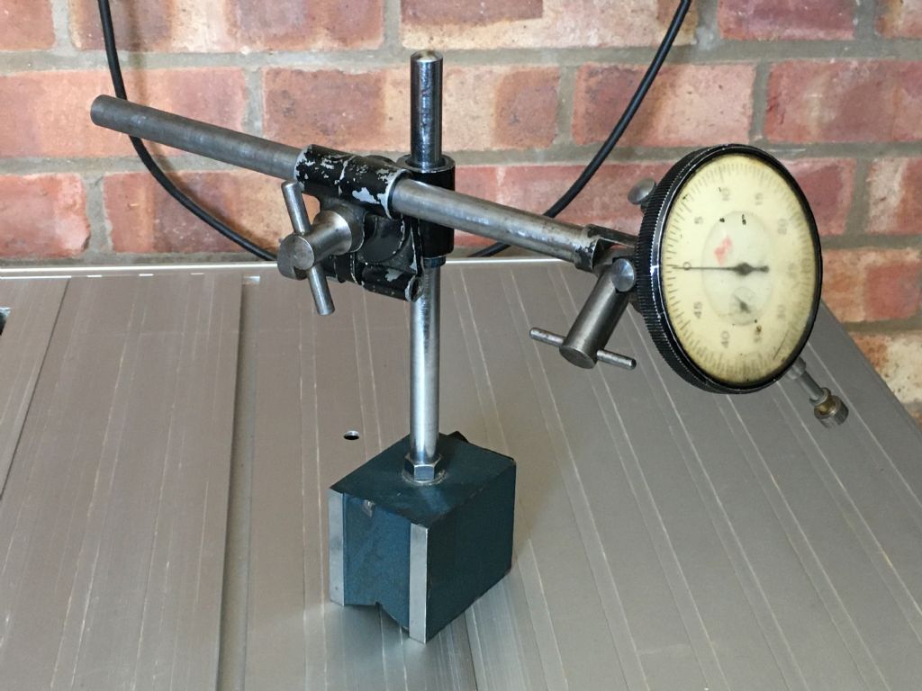
                        Or, is it an expensive Noga? My magnetic stand is quite large and the dial gauge on top is even larger. For that reason I tend to use a sensitive dial test indicator in the toolpost whenever possible, but I do need to buy a more compact magnetic stand to make setting up easier. My Batty in the magnetic stand is pictured below. I don't use it much as it's just too bulky and a pain to set up.

                        magnetic stand and large clock.jpg

                        Edited By Neil Wyatt on 30/05/2020 22:02:03

                        #476101
                        Graham Meek
                        Participant
                          @grahammeek88282

                          Mike,

                          Thanks for the info on the Bed, it does show she has had a hard life. I would hazard at a guess that the Universal Parting Tool has been used quite a bit on this lathe. There are slight nicks showing in the rear bedway which makes me think this is all Hacksaw damage. Having previously owned such an example. Luckily for me mine was not so bad and at the time I had access to the necessary equipment. An hour on the Snow Surface grinder soon had the bed back to new. The question then has to be asked why was the Hacksaw used in the first place, Inexperience perhaps? or Chatter due to a sloppy or worn bearing?

                          Looking at the wear across the bedways then on average you have roughly 1 thou more wear on the front edge when compared to the back edge at that station. This does not concern me as the tool height will only be effected by this.

                          A sloping tool path should produce a Hyperboloid of Rotation, that is the opposite to what you are getting.

                          (For those wanting more information on this then Page 88 Part Two, of Workshop Technology, by W.A.J. Chapman, Third Edition. The chapter also covers machine tool accuracy and alignments)

                          The wear pattern across the ways is more important to me at the moment, and can you tell me if you have a wide bedway bearing saddle.

                          Regards

                          Gray,

                          Generally,

                          Installing a complete workshop during a move of premises for one employer proved to be a good learning curve in installing used and abused machine tools. My training means I never take anything for granted, but check everything at least twice.

                          Regards

                          Gray,

                          #476116
                          Mike Donnerstag
                          Participant
                            @mikedonnerstag

                            Hi Gray,

                            The lathe is from around 1982. The saddle bears on the outside of the two shears (wide bed).

                            Mike

                            #476129
                            Graham Meek
                            Participant
                              @grahammeek88282
                              Posted by Mike Donnerstag on 30/05/2020 13:21:45:

                              Measuring again, apart from the last 2 inches of the bed, the bed width across both shears shows no more than 1thou of wear (not bad at all!), according to my digital calipers (the only micrometer I have is 0-1&rdquo. This includes the visibly worn area on the top of the front shear. The final 2” measures 1.5-2thou above that, which accounts for my initial wear measurement of 3.5thou.

                              Hi Mike,

                              According to the above we are dealing with ONE Thou of wear generally across the bedways. This is the generating surface for parallel parts. With an additional maximum wear of FIVE and a bit Thou in the thickness of the bedways.

                              The FIVE Thou of wear extends the entire length of the front way, where you were turning your test piece, but at the same time the wear on the rear way is roughly FOUR Thou give or take Half a Thou. Thus the tool will drop only ONE and a bit Thou, which will increase the diameter by 0.000002". This is not the 0.0015" you mention at the beginning of the post.

                              Just for reference the tool will need to drop 0.027" in centre height to produce an increase in diameter of 0,0015". Plus this drop would need to be in the middle of the test piece, ("Barrel Shaped&quot, with a gradual slope before and after to give the same diameter at each end.

                              The wear is as we have established fairly constant along the front edge, with no gradual 0.027" drop. Assuming that the Gib is adjusted correctly across the bedway then I am leaning towards the spindle adjustment. I do however think that the bed adjustments to get the two ends the same diameter originally may need revisiting, once the spindle has been checked out.

                              Regards

                              Gray,

                              #476134
                              Mike Donnerstag
                              Participant
                                @mikedonnerstag

                                I’ve just chucked up a bar that gives me around 10” from the bearing as leverage to check bearing play and found the following movement:

                                vertical: 0.0012” TIR

                                horizontal: 0.0016” TIR

                                I’ll search for previous bearing adjustment posts to see if this is ‘normal’

                                For interest, is it still possible to obtain Myford headstock spindles? I can’t see them on the Myford site, and I’d expect them to be £100s.
                                Mike

                                Edited By Mike Donnerstag on 30/05/2020 16:02:16

                                #476146
                                Martin Kyte
                                Participant
                                  @martinkyte99762
                                  Posted by Graham Meek on 30/05/2020 15:40:27:

                                  Posted by Mike Donnerstag on 30/05/2020 13:21:45:

                                  Measuring again, apart from the last 2 inches of the bed, the bed width across both shears shows no more than 1thou of wear (not bad at all!), according to my digital calipers (the only micrometer I have is 0-1&rdquo. This includes the visibly worn area on the top of the front shear. The final 2” measures 1.5-2thou above that, which accounts for my initial wear measurement of 3.5thou.

                                  Hi Mike,

                                  According to the above we are dealing with ONE Thou of wear generally across the bedways. This is the generating surface for parallel parts. With an additional maximum wear of FIVE and a bit Thou in the thickness of the bedways.

                                  The FIVE Thou of wear extends the entire length of the front way, where you were turning your test piece, but at the same time the wear on the rear way is roughly FOUR Thou give or take Half a Thou. Thus the tool will drop only ONE and a bit Thou, which will increase the diameter by 0.000002". This is not the 0.0015" you mention at the beginning of the post.

                                  Just for reference the tool will need to drop 0.027" in centre height to produce an increase in diameter of 0,0015". Plus this drop would need to be in the middle of the test piece, ("Barrel Shaped", with a gradual slope before and after to give the same diameter at each end.

                                  The wear is as we have established fairly constant along the front edge, with no gradual 0.027" drop. Assuming that the Gib is adjusted correctly across the bedway then I am leaning towards the spindle adjustment. I do however think that the bed adjustments to get the two ends the same diameter originally may need revisiting, once the spindle has been checked out.

                                  Regards

                                  Gray,

                                  The FIVE Thou of wear extends the entire length of the front way, where you were turning your test piece, but at the same time the wear on the rear way is roughly FOUR Thou give or take Half a Thou. Thus the tool will drop only ONE and a bit Thou, which will increase the diameter by 0.000002". This is not the 0.0015" you mention at the beginning of the post.

                                  How can it just affect the tool hight.?

                                  If you move the front way down by 1 thou you not only lower the tool hight but move it away from the work. The saddle must rotate about the rear way. If the tool tip was over the rear way the only movement would be horizontal by 1 thou out of the work. If the tool tip was over the centre of the front way 3.5 inches in front of the rear way and 3.5 inches above it it forms a square the back corner of whaich is fixed and the front has dropped by 1 thou, The tool tip must then rotate down by near enough one thou and out by one thou. (Just by similar triangles). The consequence is an increase in diameter of 2 thou.

                                  I woud be perfectly happy for someone to tell me the flaw in this argument. It's no different that the way we level the bed anyway. If you lower the front foot at the tailstock end you move the tool away from the work.

                                  Incidentally I think that the max wear on the bed is 0.0005" variation not 5thou. I think the 5 thou refers to the maximum amount you can take off the top of the bed before more regrinds are not possible. Myford used to mount the bed o the bedway grinder and pull the centre down by half a thou producing a bed with a hump of 0.0005" from new, with wear this goes through 'flat and eventually to 0.0005" hollow when it's time for a regrind.

                                  I'm sure there are many people more expirienced on here than me so perhaps someone could explain why I'm wrong.

                                  regards Martin

                                  #476149
                                  Mike Donnerstag
                                  Participant
                                    @mikedonnerstag

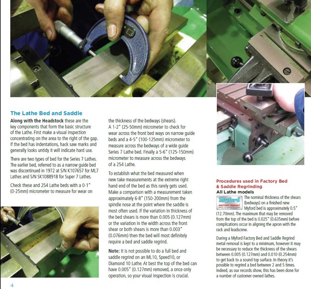
                                    Martin: The maximum wear on the bed, according to Myford, is given below, which is indeed 5thou, not 0.0005" (1/2 thou):

                                    myford factory rebuilt - bed regrinding.jpg

                                    Mike

                                    Edited By Mike Donnerstag on 30/05/2020 18:07:09

                                    #476153
                                    Mike Donnerstag
                                    Participant
                                      @mikedonnerstag

                                      Having spent the last few hours searching to no avail, can anyone tell me:

                                      1. What radial movement they would expect at the spindle nose, using a bar held in a chuck as a lever?
                                      2. How to measure the spindle end float (axial movement)? Do I need to use some kind of lever against the bull wheel for example? I understand this should be 'measured' as zero.

                                      Most of the ME threads I have been reading about setting up Myford bearings say how sensitive it all is, and several people have complained about end float resulting in the spindle locking up under an axial load, e.g. tailstock drilling. Mine runs nicely despite some fairly heavy tailstock drilling I've done recently, with no excess noise, no chatter and no locking up. I'm loathe to mess about again with the bearings unless I really need to.

                                      Many thanks,
                                      Mike

                                      #476155
                                      Martin Kyte
                                      Participant
                                        @martinkyte99762

                                        Mike

                                        That is not how I read it. The above really talks about the maximum metal that can be removed before the bed is scrap. (0.0025&quot and goes on to say that whilst they keep the material removed to a minimum they may have to take between 0.005" and 0.010" off to get to a CLEAN surface. By this I take the meaning as 'ding free'. If you use your logic you could just as well assume that the allowance is 10 thou.

                                        regards Martin

                                        #476160
                                        Mike Donnerstag
                                        Participant
                                          @mikedonnerstag

                                          Martin: Apologies – I had only given you half the information! I've updated the photo in my last post with ALL the information that Myford gave on assessing lathe beds.

                                          According to the document, the allowance in thickness is 5thou.

                                          Mike

                                          Edited By Mike Donnerstag on 30/05/2020 18:27:11

                                          #476163
                                          speelwerk
                                          Participant
                                            @speelwerk

                                            When I push very hard against the chuck with the dti set on the backplate I get less than 0.01mm movement. You can see hardly any movement of the indicator hand, it still has its factory setting from 1998. The other lathe from 1972 is much more used and gives a movement from around 0.01mm. Niko

                                            Edited By speelwerk on 30/05/2020 18:17:59

                                            #476171
                                            Mike Donnerstag
                                            Participant
                                              @mikedonnerstag

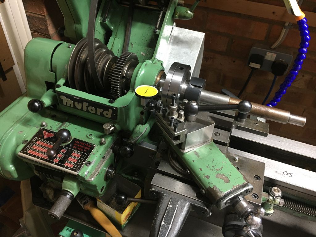
                                              Niko: I was using a bar held in a chuck, giving 10" of leverage from the front bearing, with all my might! Not that I'm all that mighty! wink I got between 0.03mm and 0.04mm on my metric gauge.

                                              Here is my setup:

                                              img_0543.jpg

                                              Anyone: Is this what you would expect?

                                              Just to reiterate my questions stated earlier:

                                              1. What radial movement they would expect at the spindle nose, using a bar held in a chuck as a lever?
                                              2. How do I measure the spindle end float (axial movement)? Do I need to use some kind of lever against the bull wheel for example? I understand this should be 'measured' as zero.
                                              3. Is it possible to obtain a 'new' spindle, if I deemed that mine needed replacement?

                                              Edited By Mike Donnerstag on 30/05/2020 18:32:00

                                              #476189
                                              speelwerk
                                              Participant
                                                @speelwerk

                                                Using your method the newer one gives 0.02 mm and the older around 0.04 mm of indicator movement. Niko.

                                                #476197
                                                Mike Donnerstag
                                                Participant
                                                  @mikedonnerstag

                                                  Niko: Interesting. So, only just under my own measurement. I think I’ll assume the bearings are adjusted okay and try something else, such as doing a test-cut between centres.

                                                  Mike

                                                  #476198
                                                  blowlamp
                                                  Participant
                                                    @blowlamp

                                                    Is the lathe turning 'round'? Machine a short length of stock and use your micrometer to check its roundness – you should lock the micrometer once set to a nice slop-free fit and rotate the freshly turned portion to feel if it is notchy or tight then loose, which would suggest that there might be a problem with the spindle or bearings.

                                                    If that is OK, then I wouldn't worry about the spindle or its adjustment too much. You don't use the test bar as a lever at all – just light to firm finger pressure will do to establish wear, any more pressure is displayed as deflection and adds to the confusion.

                                                    Don't forget that the front bearing needs some clearance for an oil film to develop when it is rotating. The fact you stated earlier on that it was cutting cleanly makes me think there's not a lot to be concerned about with the headstock in general.

                                                    Martin.

                                                    #476200
                                                    Martin Kyte
                                                    Participant
                                                      @martinkyte99762
                                                      Posted by Mike Donnerstag on 30/05/2020 18:08:40:

                                                      Martin: Apologies – I had only given you half the information! I've updated the photo in my last post with ALL the information that Myford gave on assessing lathe beds.

                                                      According to the document, the allowance in thickness is 5thou.

                                                      Mike

                                                      Edited By Mike Donnerstag on 30/05/2020 18:27:11

                                                      OK. Point taken, I was working from memory, never the most reliable of sources which is why I asked where the info had come from. It still seems a large allowance to me but if that's what they say, that is what they say.

                                                      I still would be concerned about the variation front to rear. If it was even, as has been stated it would not matter too much. I'm fascinated to see the resolution of this.

                                                      regards Martin

                                                    Viewing 25 posts - 51 through 75 (of 114 total)
                                                    • Please log in to reply to this topic. Registering is free and easy using the links on the menu at the top of this page.

                                                    Advert

                                                    Latest Replies

                                                    Viewing 25 topics - 1 through 25 (of 25 total)
                                                    Viewing 25 topics - 1 through 25 (of 25 total)

                                                    View full reply list.

                                                    Advert

                                                    Newsletter Sign-up