Marlo A3 Milling Machine

Advert

Marlo A3 Milling Machine

Home Forums Manual machine tools Marlo A3 Milling Machine

Viewing 24 posts - 1 through 24 (of 24 total)
  • Author
    Posts
  • #12366
    OuBallie
    Participant
      @ouballie

      Converting to 3-phase with VFD control

      Advert
      #166887
      OuBallie
      Participant
        @ouballie

        Back asking for more advise please.

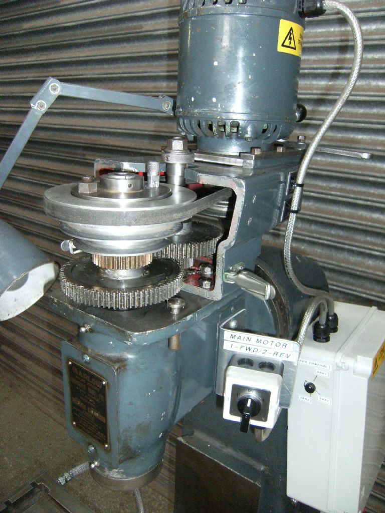
        A previous owner fitted the intermediate pulley as shown below, together with a DIY motor mount, all well done.

        That mounting plate is big and heavy!

        Now, do I leave well alone or remove?

        I do not, however, have the original motor mount with shield that bolted to the spindle pulley shield, that I do have.

        I'm very tempted to leave well alone a see how I get on with that extra pulley in the system with VFD.

        Marlo A3 Album added that has a side-on photo of that big plate.

        Geoff – A cup of Earl Grey makes a change from coffee

        Marlo A3 Milling Machine

        #166895
        Bob Brown 1
        Participant
          @bobbrown1

          The motor on my Marlow mill is a 3 phase flange mount and it is possible that in the past the motor failed and the previous owner fitted a foot mounted motor and to get the drive to work added the pulley.

          Mine runs fine on a micromaster converter and I tend to use the middle ratio on the pulleys for most jobs allowing the micromaster to vary the speed.

          Does yours have one belt or two?

          Bob

          #166925
          Robbo
          Participant
            @robbo

            Bob is right in his suggestion that a previous owner has used a foot mount motor (mounted on that bracket at the rear) and added an intermediate pulley to increase the range of speeds available on the pulleys, and has removed the original backgear.

            Originally had a flange mounted motor with 3-speed pulley drive and a further 3 speeds available through the backgear.

            I don't think there is much option other than to stick with what you've got unless you want to do another complete redesign of the drive system.

            Picture attached of how it originally looked. Apologies if you already know this

            Phil

            Note for H&S –  front cover removed so we can see the innards


            marlow-2.jpg


            Edited By Robbo on 18/10/2014 21:57:56

            #166927
            Bob Brown 1
            Participant
              @bobbrown1

              Mine is not like that as it has no gear wheels just belt driven 5 speeds originally but variable now due to the micromaster converter. I think mine originally went from 375 to 2250rpm and the geared 6 speed version from 85 to 1450rpm.

              Edited By Bob Brown 1 on 18/10/2014 22:06:47

              #166934
              Robbo
              Participant
                @robbo

                Bob,

                I think the detailed spec varies depending on where the machine was built. You can see from the plate that Geoff's was made by Victa Engineering, I've forgotten where that was, but mine was made by Dronsfield Brothers in Oldham.

                Even so my feedscrews are different from those detailed in Dronsfield own advertising literature. There is sparse information on when and where they were built

                Phil

                #166963
                Robbo
                Participant
                  @robbo

                  Memory let me down again, so once more talking bo****ks.

                  Found my Marlow advertising leaflet, and there were 2 drive options, the 5-speed direct, and the 6-speed with backgear and 3-speed pulley. The 5-speed is illustrated on the leaflet.

                  So Bob's and Geoff's are the 5-speed option, mine is the 6-speed.

                  Bob is quite correct about the speeds, 375 – 2250 on the 5-speed, and 85 – 1450 on the 6-speed. Given the noise the backgear makes, a VFD would make for a quieter life on the 6-speed.

                  Geoff, with a VFD fitted, why not forget the intermediate pulley and have a direct 5-speed from motor to spindle.

                  Oh, and Victa Engineering were in Maidenhead.

                  Phil

                  #166969
                  Bob Brown 1
                  Participant
                    @bobbrown1

                    On either of the original drive designs changing speeds was reasonably easy as it it's just a case of releasing the lock and moving the motor forward, change the position of the belt and then tighten up and lock. Not sure how this is achieved on the three pulley set up.

                    Mine runs almost silent!

                    Bob

                    #166976
                    OuBallie
                    Participant
                      @ouballie

                      Thanks once again guys.

                      Bob,

                      One belt, and the motor had a 3-step pulley ranging from 65-48mm measured at the outer edges, 5/8" shaft.

                      New motor has 24mm shaft so a new pulley ordered from RDG.

                      The intermediate pulley is easy to remove, but I think I will use it as a jockey pulley, as a belt from motor to spindle will be somewhat long with possible mismatch with pulleys, so a bit of tensioning will not go amiss I think. Can always remove it.

                      Robbo,

                      Its the first time I've seen that set-up.

                      The motor I've taken off is a 1hp Gryphon, foot mount.

                      The thought of redesigning the drive train fills me with the heeby jeebies. Let's play with what I have.

                      Geoff – Those Russian dash cam videos make me glad I drive in this country!

                      #168346
                      OuBallie
                      Participant
                        @ouballie

                        !WHOOHOO!

                        It's actually running, after sitting in the Workshop since 2008

                        Haven't used it in anger yet, but photos and details to follow.

                        Just one more thing to do, and that's to connect power to the Power Feed motor, but I need help please with wiring it up.

                        The machine came with a box of switches and cable, but no info on how they should be connected to the motor.

                        There is a connection box on the side of the motor, with five wires coming out, namely, white, red, green and two yellow.

                        No idea if the motor even works or not.

                        Geoff – Satisfactory week

                        #168349
                        Bob Brown 1
                        Participant
                          @bobbrown1

                          Mine did not have a power feed so can not help with the wiring but I have fitted a BLDC motor and variable speed controller with a belt drive which works really well.

                          Bob

                          #168356
                          Les Jones 1
                          Participant
                            @lesjones1

                            Hi Geoff,
                            Is there any information on the motor to suggest if it AC or DC ?

                            Les.

                            #168361
                            Bob Brown 1
                            Participant
                              @bobbrown1

                              As the original motor is 3 phase then as a thought, a 3 phase motor only needs 2 phases reversed to change direction. That said it could be single phase a pair as run terminals, a pair as start and an earth, I doubt very much if it is original that it is DC.

                              Anything under the motor terminal cover?

                              Bob

                              #168379
                              WALLACE
                              Participant
                                @wallace

                                Hi Robbo.

                                Mine’s the same as Phils – and changing belts is a doddle. Just wondering if it’s possible to convert a foot mount motor to a flange one ? Can’t imagine it would be too difficult to add a flange to the existing end plate of the motor with a lathe ! Do you have the original motor mount and pulley guard with your machine ?

                                I also run mine of a vfd – the one disadvantage I’ve found is the few seconds it takes to run up to speed – if you try to take a cut before it has,it’s easy to break the cutter !!

                                No feed on mine so I can’t help you there I’m afraid – but I do like my machine – the eventual plan is to cnc it which will be fun !

                                W.

                                #168381
                                Gary Wooding
                                Participant
                                  @garywooding25363
                                  Posted by WALLACE on 02/11/2014 00:33:26:

                                  I also run mine of a vfd – the one disadvantage I've found is the few seconds it takes to run up to speed – if you try to take a cut before it has,it's easy to break the cutter !!

                                  Can you not change the Acceleration Time parameter? On my Mitsubishi VFD it's parameter 7. Parameter 8 is for the Deceleration Time.

                                  #168387
                                  WALLACE
                                  Participant
                                    @wallace

                                    Hi Gary.

                                    Yes….but I also use it to drive the lathe and I prefer the slower run up as it’s quite big – the 4 jaw is a 9″….

                                    It’s a bit awkward as well – it’s done by a preset on the main pcb – it’s a home made one based on the Elektor design published quite a few years ago.

                                    I’ve got used to it now and will wait before taking a cut – I have half a broken 16mm end mill on the shelf as a permanent reminder !

                                    W

                                    #168410
                                    OuBallie
                                    Participant
                                      @ouballie

                                      More photos just added to the Album.

                                      Replies:

                                      Bob,

                                      Details of mounting the BLDC please.

                                      Les & Bob,

                                      Cannot see any terminal cover or info about the motor.

                                      As can be seen in the photos, the motor is at the rear of the column and up against the wall, and even a mirror doesn't show any plate that may of course be on the underside of said motor.

                                      General:

                                      Fitted the new pulley to the motor shaft then an 'Oh' as the largest step prevented the motor from being bolted to the upright, so four spacers made from 20mm sq tubing and all well.

                                      Now came the time to 'gird ones loins' and heave that combination up onto that aircraft carrier size plate on top of the milling machine, and catch my breath once done.

                                      Now to get that unwieldy assembly into place to slide into the square 'dovetails' but an 'OH B@LL@cks' as the pulley got in the way! Once I'd calmed down and thought in a calmer mood, I realised that the only solution was to remove one of the pulley steps, and for some reason chose the largest diameter step, so off it came, into the lathe and the use of parting tool and boring bar had that step cleanly sheared off. Didn't fancy reducing it to swarf, so now have two pieces of possible useful packing.

                                      Pulley back and it all fitted as before, ordered a V-belt for motor to intermediate pulleys and wired up the VFD whilst waiting for the belt. I could probably remove the motor spacers, but life's just too short, so they are there for keeps.

                                      Switch everything on, twiddle the VFD frequency knob, and motor sprang into life, for the first time since I got the machine.

                                      I did a jig around the Garage floor in celebration and relief.

                                      The VFD is on a bracket that hangs from the OverheadCrane DIN rail, and easily taken out the way.

                                      Just need to sort out the table power feed now.

                                      Bolted one of the aluminium trays and the packing block set to the LH and RH side of the column respectively.

                                      Geoff – Finish the Tom Senior next.

                                      #168413
                                      Bob Brown 1
                                      Participant
                                        @bobbrown1

                                        My mill is a tad inaccessible at the moment as I await a load of concrete (Wednesday) to complete the floor and once that is dry (week or 2) arrange the workshop/garage.

                                        dscf0416.jpg

                                        Its all in there somewhere!

                                        #172413
                                        OuBallie
                                        Participant
                                          @ouballie

                                          Need help from the Collective please.

                                          Last stage to finish the Auto-eject drawbar, made from the Hemingway kit.

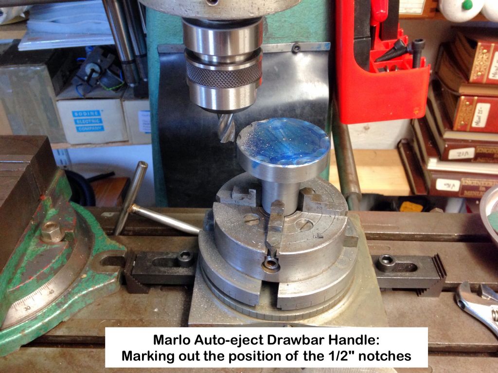
                                          I need to machine the half round 1/2" notches in/around the periphery of the handle.

                                          Any ideas please.

                                          This set-up for marking them out is just a little light weight for either a slot drill or milling cutter:

                                          Marlo A3 Milling Machine Drawbar

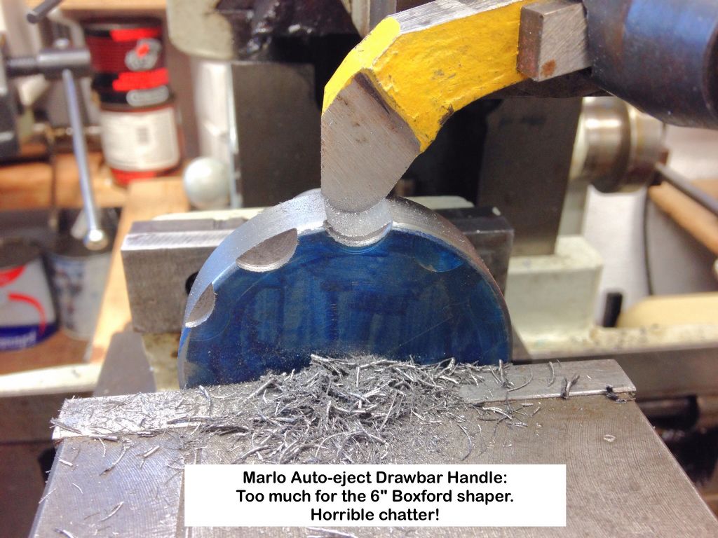
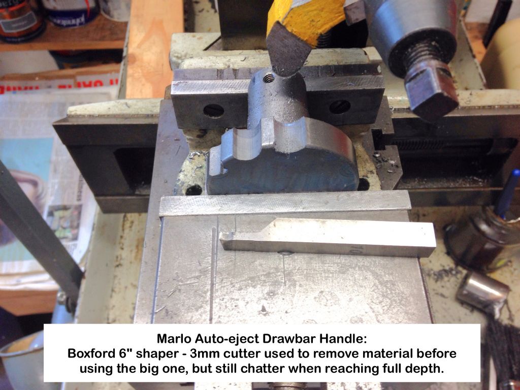
                                          This on the Boxford 6" just produces such monumental chatter, it feels as if the shaper will shake itself to pieces:

                                          Marlo A3 Milling Machine Drawbar

                                          Have used the 3mm cutter to remove material first:

                                          Marlo A3 Milling Machine Drawbar

                                          Geoff – Actually getting things done disgust

                                          #172415
                                          Bob Brown 1
                                          Participant
                                            @bobbrown1

                                            If I was doing that job I would use a round nose (ball) cutter in the mill


                                            Edited By Bob Brown 1 on 13/12/2014 14:21:53

                                            #172434
                                            OuBallie
                                            Participant
                                              @ouballie
                                              Posted by Bob Brown 1 on 13/12/2014 14:20:06:

                                              If I was doing that job I would use a round nose (ball) cutter in the mill

                                              Edited By Bob Brown 1 on 13/12/2014 14:21:53

                                              "Damn and blast" as my old man was fond of saying when something obvious was pointed out.

                                              I have one of those, as well as the Excel filing machine that has been giving me verbals for not remembering what it's used for.

                                              May have already made too much of a whatsits so far, but will see tomorrow.

                                              Geoff – teeth crying 2 face 7 Time for a cup of Earl Grey to calm down.

                                              #172513
                                              mechman48
                                              Participant
                                                @mechman48

                                                I would have used a 1/2" slot mill in the mill machine & plunge cut down or an end mill coming in from the OD as in your original set up, just take lighter cuts, or use a ball end mill as said, bearing in mind theoretically you can cut a depth of 1/2 the cutter dia. X 1/4 the width with an end mill… or is it Viky verky…. thinking , the old grey matter is slow today.

                                                George.

                                                Edited By mechman48 on 14/12/2014 12:25:48

                                                #172549
                                                OuBallie
                                                Participant
                                                  @ouballie

                                                  George,

                                                  I did try that way, but I was either too greedy with the cut or that DIY rotary table is not up to it, so gave up.

                                                  Drawbar:

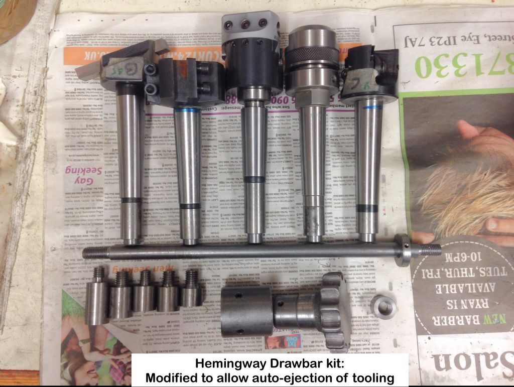
                                                  I have just finished it and the photo shows all the completed parts, plus at bottom left, my first attempt at the MT tool extensions that have now been added to the scrap bin.

                                                  In my post when I said I had sorted the height of those extensions to allow the use of one drawbar, I spoke far far too soon, with fate giving me a real kick in the posterior.

                                                  I could not have made a bigger codswallop even if I tried, and then spent days trying to figure out where I went wrong, but eventually giving up in utter disgust with myself.

                                                  That was on Friday 28th November! I know I know, slow coach.

                                                  Then on the Saturday I thought (bad move) that I had sussed it out using Touchdraw on the iPad, but no, so retired to recuperate and give the old grey matter time to come to its senses.

                                                  Tuesday 2nd of this month brain at last started to operate, and I came up with the perfect solution of determining what length to make those MT tool extensions so that they all reached the same height inside the spindle, when screwed onto each tool.

                                                  The method I used can be seen on two of the MT tools in the photo.

                                                  Who can see how/what I did?

                                                  Will explain later of course if needed.

                                                  The handle was finished off using a combination of Excel filing machine, hand file then small grind stone in the battery drill.

                                                  The Auto-eject collar is attached to the drawbar, with the spindle cap, that the collar pushes against, and handle below.

                                                  All the 3MT tooling is shown at top, each fitted with its specific extension that allows for a single common drawbar to be used.

                                                  It took a little trial & error to get it to eject the 3MT tool, but does so now with about a 1/10th turn of the bar.

                                                  All I can say is that the time and angst this has caused me has proved well worth the effort, and I can recommend the system without reservation.

                                                  Now need to do one for the Tom Senior horizontal arbor.

                                                  Geoff – It feels good when something comes to a satisfactory conclusion beer

                                                  #172618
                                                  OuBallie
                                                  Participant
                                                    @ouballie

                                                    Oops.

                                                    Alway better late than never.

                                                    Milling machine auto-eject drawbar

                                                  Viewing 24 posts - 1 through 24 (of 24 total)
                                                  • Please log in to reply to this topic. Registering is free and easy using the links on the menu at the top of this page.

                                                  Advert

                                                  Latest Replies

                                                  Home Forums Manual machine tools Topics

                                                  Viewing 25 topics - 1 through 25 (of 25 total)
                                                  Viewing 25 topics - 1 through 25 (of 25 total)

                                                  View full reply list.

                                                  Advert

                                                  Newsletter Sign-up