Knurling/Nurling tool

Advert

Knurling/Nurling tool

Home Forums General Questions Knurling/Nurling tool

Viewing 19 posts - 1 through 19 (of 19 total)
  • Author
    Posts
  • #281775
    bricky
    Participant
      @bricky

      Reference the plan in the February issue of MEW of the nurling tools by T H Miller.I am interested in making the bottom one. As my existing nurling tools centres are verticle I wandered if someone could explain the merits of the approximate 10 deg angle of the centres.

      Frank

      Advert
      #25056
      bricky
      Participant
        @bricky
        #281790
        Neil Wyatt
        Moderator
          @neilwyatt

          Hi Frank,

          Having read the patent, I think that's a bit of a mystery, however note that (unlike more modern designs) there is a pivot in the shank so the head can 'nod up and down' to find the best position – not obvious from the drawings. This means the actual angle doesn't matter, but neither does the height of the tool in the toolpost.

          It's abit late for us to ask Mr Miller!

          Neil

          #281792
          Clive Foster
          Participant
            @clivefoster55965

            Mr Miller probably thought that the angle would make the tool more stable in cut than a vertical arrangement.

            With the centres vertical the point of contact of the knurls on the workpiece and the rotationa centres of workpiece and knurls all lie on the same straight line. Any attempt by the workpiece to squirm sideways will pull it out of cut so it will continue to pull out.

            With the centres at an angle the points where the knurls engage the workpiece no longer lie on the same straight line as the rotational centres of knurls and workpiece. Hence it is possible to arrange things so that if the workpiece tries to get out from under the knurls the effective cutting forces increase pushing it back central. Cleary the system isn't symmetrical so any anti-squirm effects one way are balanced by similar pro squirm the other so things only behave if the workpiece is turning the right way. Looks as if the whole thing falls apart for anything more than small angles of offset. Effect also reduces as the workpiece becomes larger. But larger workpieces are stiffer anyway so the reducing potential problems. I suspect that once you get workpieces beyond 1/4" to 1/2" diameter the whole thing becomes moot anyway.

            Practice has shown that conventional vertical alignment of the knurls works fine. But small parts will try to squirm out if you are careless setting up. So its not completely theoretical.

            Clive.

            #281800
            Clive Foster
            Participant
              @clivefoster55965

              Neil posted while I was typing. His points about the effect of pivoting are valid and best dealt with separately anyway as they really apply more to conventional push knurls.

              Push knurl tools are generally set on a pivoted carrier to provide inherent equalisation of forces between the knurls which should promote nice even knurling with no mis-registration. In the conventional arrangement the pivot is on centre height with one knurl a little above and the other a little below centre. This vertical spacing also generates forces apposing any attempt by the workpiece to climb out of engagement with the knurls. Although this generally more or less works you need a hefty, steady, push to keep things working properly. Its generally considered that small lathes aren't really up to generating the necessary forces for reliable push knurling which is why scissors types are favoured. Even on larger machines care is needed on small workpieces which can easily bend and run away from the knurls.

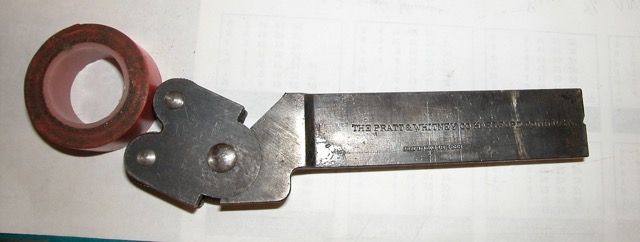
              There is an alternative, somewhat uncommon, arrangement of push kurling tool where the knurl carrier is L shaped with the pivot low down and slightly above the bottom arm of the L. In use the upper knurl is pretty much on the centre line of the workpiece whilst the lower knurl pivots up from below the centre line. The knurls engage sequentially with the upper one contacting first and pulling the lower one up into engagement from below. I have a couple of such tools made by Pratt & Whitney and find them well behaved. Sequential engagement of the knurls means you don't have to slam the tool into the workpiece so hard and the pull up from below arrangement seems to keep the second knurl tracking accurately. Especially on small parts. Doesn't seem to be of any great advantage on parts over 1 1/2" or so diameter.

              I imagine that Mr Miller was thinking along the same lines as the man who devised the arrangement used on my Pratt & Whitney tools. My experience is that the lower pivot point really is of benefit with push knurl tools but whether than reads across to clamp types I know not. It occurs to me that playing about with pivot height relative to workpiece diameter could theoretically improve knurl stability. I wonder how good and how sharp knurls were in those days?

              Clive.

              Edited By Clive Foster on 01/02/2017 19:20:52

              #281809
              Neil Wyatt
              Moderator
                @neilwyatt

                My home made knurling tool has pivots for both the top and bottom arms, so it 'floats' into proper alignment.

                With the centres at an angle the points where the knurls engage the workpiece no longer lie on the same straight line as the rotational centres of knurls and workpiece.

                I don't think that's true as each of his drawings actually shows a straight line, angled, but through all five points.

                Neil

                #281860
                John Reese
                Participant
                  @johnreese12848

                  I learned several years ago that it was not possible to get a good knurl if the centers of the knurls were on a diameter of the workpiece. Because of backlash in the cross slide the knurling tool would drift. I found that setting the opening between knurls a bit less than the part diameter solved the problem. It maintained a constant force against the cross slide and eliminated drift, I don't know if the makers of the tools mention that in their instructions. I have never seen an instruction sheet for a commercial knurling tool.

                  #281876
                  bricky
                  Participant
                    @bricky

                    Thanks for the corrections Tim ,But as you didn't contribute to the post I don't know why you bothered on my spelling mistakes ,this forum must keep you very busy.Have you got a valid explanation to my question I think that would have been a better response.

                    Frank

                    #281883
                    not done it yet
                    Participant
                      @notdoneityet

                      Tim's point is a serious one. All these threads are archived and available for others to access and learn, so others do not necessarily ask the same question over and over again.

                      At least the title needs to be right for one type of search. There is a lot to be learned from the forum by searching a topic, but the search is not quite so sophisticated as a 'goggle' search which will offer alterntives. 'Fymord' instead of 'Myford'would not be useful to most Myford owners who use the search facility.

                      So Tim is helping the whole forum membership, potentially. I know nowt about knurling. I have used straight knurlers but will now make a/some scissor type(s) in the future.

                      #281889
                      Neil Wyatt
                      Moderator
                        @neilwyatt

                        Actually nurling is a valkid spelling, although an old one, I am sure I have seen it in old MEs. Up until the 1880s 'nurling' was the more commons spelling, according to Google ngram viewer. It had a resurgence in the 1900s and nearly overtook knurling again, but it faded away by the mid 40s.

                        I will change the title to 'knurling' to help searches

                        I deleted Tim's post, not because of the knurling correction, but because we really don't need anyone picking apart other people's postings. Let him who is without sin cast the first stone.

                        Neil

                        #281892
                        Allan B
                        Participant
                          @allanb

                          Thanks for that nugget of information, I have it all the time with students spelling knurling without the K (most of the low level students have some form of learning difficulties) so at least I can now get the government and college grammar police off there backs 😂😂😂

                          #281920
                          Clive Foster
                          Participant
                            @clivefoster55965

                            Neil

                            Judging by the behaviour of my Pratt & Whitney tools I don't think a device with the single offset pivot is going to be unconditionally stable with the contact points on the same straight line as the rotational centres of knurl and workpiece. Of course we will never know until someone builds one and reports back from practical experience.

                            Nice knurling demands equal depths of cut on both knurls which implies equal forces. With the conventional floating twin pivot type clamping down hard pretty much ensures equal forces because you effectively have a parallelogram link system, with no inherent stiffness at the joints, floating around the two pivots and two contact points. So long as the system is strong enough to withstand the cutting forces, which are asymmetrical due to work piece rotation, the system stays balanced.

                            With a single offset pivot you have the option of dynamic balance essentially driven by the cutting action where things settle at the lowest force on knurl point. Done right the forces on the knurls will be equal at the stable point. Any shift in position to unbalance the system increases the force on the pivoted knurl driving things back to the equal force position. Clearly the dynamics fall apart once driven past the straight line position drawn in the patent. Patent drawing are diagrams rather than manufacturing anyway. Given the date of the patent its unlikely that there was any proper engineering analysis involved. I suspect that Mr Miller followed a similar sort of handwaving and "just felt" that such a layout would self balance and work better than a vertical set-up. It would be interesting to know why he didn't go straight to the now normal two pivot layout anyway. I can't believe it didn't occur to him.

                            With a big lathe and normal push knurling tool you just lean on it so hard that all the clever bits get flattened like a walnut under a steamroller. Sometimes BF & I is the way to go!

                            Clive.

                            #281922
                            John Stevenson 1
                            Participant
                              @johnstevenson1

                              Clive,

                              Any chance of any pictures as I'm struggling to envisage this P&W knurling tool. ?

                              #281924
                              Neil Wyatt
                              Moderator
                                @neilwyatt

                                Clive,

                                Miller DID have two pivot points on all but one of his four suggested layouts, it isn't obvious at a glance, but do look again.

                                Imagine rotating the drawing until the line in the patent drawing is vertical, I don't think the angle affects the mechanics at all.

                                I think all the illustrated layouts (including the second page) allow equal and opposite forces on the knurls, and just like modern ones the skill is in applying the right degree of force and moving the toolpost back and forth to get the knurls more or less diametrically opposite for best results.

                                Miller's second page of drawings shows a block being placed between the arms to lock them, and allow them to be used as a standard swivelling push tool on larger work. This is an interesting idea I could use with my own scissors knurl.

                                I think Miller got it dead right first time, and I don't think modern versions are materially different from his designs.

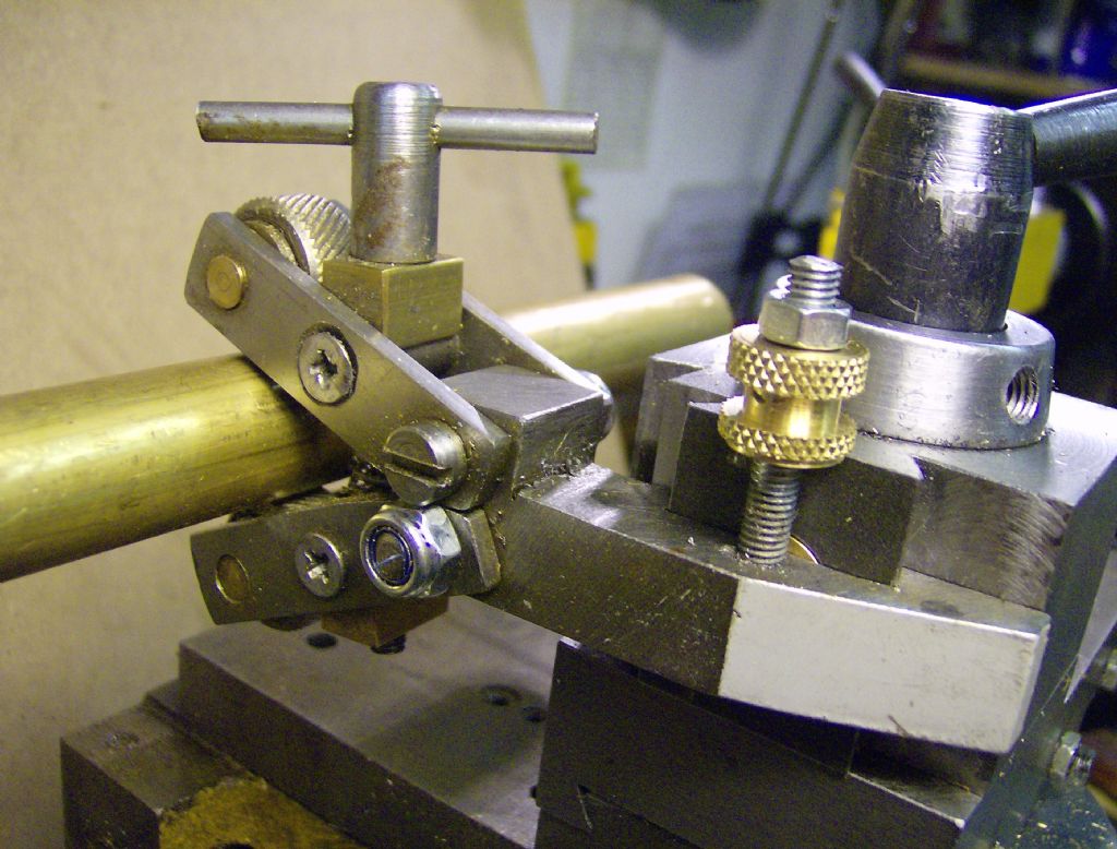
                                I also feel that the forces required for knurling are sometimes over-estimated. My own knurls use a high-tensile M4 bolt to apply the knurling pressure and have lasted years. Both the examples below were push-knurled on a mini lathe without distressing it, and you can see how flimsy my scissor knurl is! I'll let others be the judge of the quality of the results…

                                Neil

                                handwheel dial to graham meek design.jpg

                                bench block.jpg

                                QCTP Knurling Tool

                                #281954
                                Clive Foster
                                Participant
                                  @clivefoster55965

                                  John

                                  Picture of Pratt & Whitney Knurling Tool as requested mocked up with roll of tape to show the position I normally use it in.

                                  dscn2070.jpeg

                                  Patent date stamped on it is December 18 1888. I've tried to find the patent but no luck. I have another clearly later one without the patent date stamping. When it first arrived I simply set it up with the upper knurl on centre and it worked very well indeed. Almost proof against mis-tracking but you can get a bad knurl if really casual. Clearly less pressure needed than with common modern form with the knurls running at more or less equal offsets above and below centre. Out of curiosity I tried setting it up with the pivot as close to centre line as possible, didn't work at all well. So it is geometry not just having a super set of knurls.

                                  Neil

                                  Page 1 of the patent is interesting demonstrating the Mr Miller clearly could have come up with the modern form with two symmetrically disposed pivots. However he clearly decided that the best way to do things was to arrange things asymmetrically with only a single pivot between the two arms. The geometry and relative disposition of forces in his arrangements changes once you move off the dead centre position. The modern layout is essentially constant force at any reasonable set up position so any wobbling around, with reason, makes no difference. Mr Millers arrangements have different effective lever lengths between pivot and knurl contact points so any movement does change things.

                                  Interestingly Mr Millers Figure 3 is effectively an adjustable version of my Pratt & Whitney tool. But his Figure 1 shows it set to a geometry effectively the same as the modern form of straddle clamp tool. Given that tooling was relatively far more expensive in those days it makes sense to have a single tool that can be configured in straddle clamp form for small workpieces and bump push for larger ones. But that can be done as easily with the modern symmetrical form as it can with those shown. So the question remains why go to the extra bother of asymmetry. That said the P&W tool does work very well indeed. P&W made bench and instrument lathes in those days so I guess they knew what worked best on these small, low powered and somewhat lightly built yet very accurate machines.

                                  Clive.

                                  #281988
                                  Neil Wyatt
                                  Moderator
                                    @neilwyatt

                                    Let's just agree to disagree on how we interpret the way the forces work!

                                    I think his two stage pivot method gives equal force however you set it – you obviously don't and prefer two symmetrical pivots.

                                    Let's just agree to disagree on how we interpret the way the forces work!

                                    Neil

                                    #282002
                                    Neil Wyatt
                                    Moderator
                                      @neilwyatt

                                      Footnote:

                                      I've been reminded that Miler himself called it a 'nurling tool' and that's how it's spelled in the patent. I've changed the title again to include both spellings but Bricky is totally exonerated! No doubt the old spelling lodged in his brain after reading the page in MEW which presumably some other people didn't read…

                                      Neil

                                      #282006
                                      JasonB
                                      Moderator
                                        @jasonb

                                        Clive could the same effect as your P&W one by achieved simply by mounting a common or garden pivoting head knurl lower than normal as that looks like it would act in the same way.

                                        The work won't know if the shank is straight or L shaped so long as the pivot point is below ctr line of the lathe.

                                        J

                                        #282035
                                        Clive Foster
                                        Participant
                                          @clivefoster55965

                                          Jason

                                          See no reason why not but my version of the ordinary one doesn't have enough movement to take up the same angles. Pivot radius is rather less too. So it probably wouldn't be a valid test. Knurl size is about the same tho'. Can't get it low enough on either of my lathes or I'd have given it a try just to see.

                                          Its bugging me that the asymmetric layout was clearly seen as the better back in the 1890 to 1900 + whatever period. Symmetrical one knurl above centre and one equal amount below is obvious way and has since become the norm. So why was it done differently in those days and the less obvious approach considered to be sufficiently important to be worth patenting by Pratt & Whitney who were a serious company.

                                          Neil

                                          Yup we shall have to agree to differ on this.

                                          Clive.

                                        Viewing 19 posts - 1 through 19 (of 19 total)
                                        • Please log in to reply to this topic. Registering is free and easy using the links on the menu at the top of this page.

                                        Advert

                                        Latest Replies

                                        Home Forums General Questions Topics

                                        Viewing 25 topics - 1 through 25 (of 25 total)
                                        Viewing 25 topics - 1 through 25 (of 25 total)

                                        View full reply list.

                                        Advert

                                        Newsletter Sign-up