Internal Key-way Shaping

Advert

Internal Key-way Shaping

Home Forums General Questions Internal Key-way Shaping

Viewing 25 posts - 26 through 50 (of 63 total)
  • Author
    Posts
  • #510120
    IanT
    Participant
      @iant
      Posted by Hopper on 27/11/2020 04:48:28:

      Posted by Nigel Graham 2 on 24/11/2020 00:15:33:

      * The shaper. I do know too that the cutting edge should be under the clapper fulcrum, but learnt that only quite recently, and I have seen and probably been guilty of some very unfair tool-setting on shapers.

      Carry on the way you have been doing it and you will be just fine. I can't think of any good reason why the tool should be directly below the fulcrum — unless there is something special about the model-sized machines?

      The reason this is often mentioned Hopper is in relation to "cranked" tools (a swan-neck for instance). On a lathe, a dig-in will tend to pull the cutting edge away from the surface being cut (this surface being round). On a shaper, a dig-in where the cutting edge is in front of the fulcrum will dig-in further (the surface being flat). If the cutting edge is inline or behind the fulcrum, it will be pulled 'out' of the cut. I think Nigel has been looking at Bradleys shaper book or similar – it's mentioned there.

      I have some forged swan-neck tools and there are two types. Those with the cutting edge inline with the top of the tool shank are for lathe use and those with the cutting edge inline with the bottom of the shank are for shaper use. Obvious when you know the reason.

      In practice (using normal tooling) – it's something to be aware of – but not to worry about too much. Just don't over extend the tool (or vertical slide) to avoid any unnecessary deflection and don't take too deep cuts. Also don't "pack" the tool bit to the fore, always get the cutting edge back as far (near to the clapper) as possible.

      Basically try to avoid dig-ins.

      Regards,

      IanT

      Edited By IanT on 27/11/2020 10:21:41

      Advert
      #510135
      Hopper
      Participant
        @hopper

        Crikey. Swan neck tools haven't been used since Noah was a midshipman. But I guess many shapers are of that vintage!

        Possibly more of a concern on the small hand driven jobs than the big industrial Cincinnatis, I would guess.

        But I still cant see how having the tool point in line with the clapper pivot would make a jot of difference to a dig-in because the clapper does not pivot in that direction at all. It is for all intents and purposes fixed on the forward stroke, held firmly against the end of the ram by the pressure of the cut. Surely, its the swan neck tool that does the moving and allows the tip to spring that tiny bit away from the job?

        Interesting.

        #510143
        Hopper
        Participant
          @hopper

          PS all you ever wanted to know about shapers, and then some more, is probably to be found among this amazing collection of PDFs of old shaper manuals and all sorts of other good stuff. (All out of print and copyright by now.)

          http://www.neme-s.org/Shaper%20Books/

          Edited By Hopper on 27/11/2020 11:07:12

          #510950
          Nigel Graham 2
          Participant
            @nigelgraham2

            I've been searching for the text-book I have / had that goes into quite a bit of detail on using the shaper.

            Things vanish in my house and workshop, but I've a sneaking suspicion I lent the book to a friend… before the Covid World Tour.

            I'd wanted to quote from it. Among other things I a m pretty sure it shows the geometry of the tool action, explaining the effect of tool distance from the fulcrum. However I did look in one or two of my old industrial (rather than model-engineering) books, as these show sample machines most of us could not accommodate. In these the shapers do appear intended used rather as in Hopper's photo – no mention of hats though – but that could be misleading.

            A dodge I have found helpful is to file a chamfer along the leading edge of the work, so the tool is slightly eased into the metal rather than having to chop into a vertical face.

            What I also recall from the AWOL book, which I think is a model-engineering text rather than an apprentice-training reference, is a simple shaper tool-holder based on an old bicycle crank. It is trimmed (by shaping?) to fit the clapper box, and a cylindrical holder for round-section tool-bits fits in the crankshaft hole. It was designed for down-cutting both sides of the work as well as the top, with just a simple adjustment.

            * * *

            My original enquiry was prompted by having to build a drive for a small horizontal mill (motor speed nearly 1400rpm, spindle around 60rpm), and thinking of the 2-speed transmission for my steam-wagon – for which there are no drawings.) I've taken a break from the mill project as I'd hit a sort of impasse, to complete a Hemingway kit 'Worden' T&C grinder I started ages ago. That has full drawings, a luxury despite the frustrating way some parts are dimensioned!

            #510960
            Hopper
            Participant
              @hopper

              The link above has manuals for Boxford and other small shapers that might be useful. No hand power that I saw.

              #510966
              not done it yet
              Participant
                @notdoneityet

                A dodge I have found helpful is to file a chamfer along the leading edge of the work, so the tool is slightly eased into the metal rather than having to chop into a vertical face.

                Not a dodge at all. A veritable necessity when cutting hard materials with a hand shaper, particularly if taking a roughing (heavy?) cut.

                #510979
                Ex contributor
                Participant
                  @mgnbuk

                  A dodge I have found helpful is to file a chamfer along the leading edge of the work,

                  A filed or angle grinder ground chamfer was also put on the exit edge of cast iron components when shaping or planing to help prevent the corner from shelling off.

                  The machinists at work mill a chamfer all round the edge of graphite blocks before facing a surface for the same reason.

                  Nigel B.

                  #510985
                  John Haine
                  Participant
                    @johnhaine32865

                    I've only had to do one keyway for which I used the lathe (S7) and fed with the rack. It was tedious but worked, in a pulley that I had to sleeve to fit a motor shaft when I added a VFD to my mill.

                    I have wondered whether the leadscrew would be stronger than the rack – though tedious by hand, since my lathe has CNC one could write a bit of G code that simply drives the Z axis back and forth over the required distance and slowing adds X feed to put the cut on. The same thing might be done on a CNC mill. My lathe has the standard Acme leadscrew on Z.

                    #510987
                    Ady1
                    Participant
                      @ady1

                      Anything that removes material will make life easier for the final cutting

                      Hacksawing, filing, drilling

                      #511002
                      Hopper
                      Participant
                        @hopper
                        Posted by John Haine on 01/12/2020 09:52:58:

                        I've only had to do one keyway for which I used the lathe (S7) and fed with the rack. It was tedious but worked, in a pulley that I had to sleeve to fit a motor shaft when I added a VFD to my mill.

                        I have wondered whether the leadscrew would be stronger than the rack – though tedious by hand, since my lathe has CNC one could write a bit of G code that simply drives the Z axis back and forth over the required distance and slowing adds X feed to put the cut on. The same thing might be done on a CNC mill. My lathe has the standard Acme leadscrew on Z.

                        Could be a bit wearing on the old halfnuts I reckon.

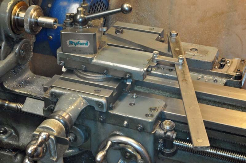
                        LH Sparey or Ian Bradley suggests an easy way of converting the existing topslide into a slotting cutter by removing the topslide feed screw and using a long lever to crank the topslide back and forth.

                        The lever is pivoted on a bolt sticking up from a piece of 2" round bar stood on end and bolted to one of the cross slide T slots behind the topslide. And is attached to the topslide via a nut and bracket etc on the toolpost clamping stud. Lever then sticks out about another 18" or so. Easier to crank and no stress on feedscrews or racks etc.

                        I swore after the last time I tediously slotted a faux-Myford change gear using the rack method I will never do it again and will make one of the above.

                        A bit of fettling and a variable stop could be made to use it for engraving lines on handwheels and the like.

                        Edited By Hopper on 01/12/2020 10:45:14

                        #511009
                        Roderick Jenkins
                        Participant
                          @roderickjenkins93242

                          Like this:


                          slot 1.jpg

                          I think it's  a Len Mason design.  Came with my s/h lathe.

                          Rod

                          Edited By Roderick Jenkins on 01/12/2020 11:19:33

                          #511043
                          IanT
                          Participant
                            @iant
                            Posted by Hopper on 27/11/2020 10:54:18:

                            Surely, its the swan neck tool that does the moving and allows the tip to spring that tiny bit away from the job?

                            Yes, exactly Hopper – it's the tool and/or holder flexing that was being addressed. Some shaper set-ups require quite a lot of tool extension – usually for 'reach' reasons, where the tool has to be over-extended to get to the bottom of a cut (without the ram or slide fouling).

                            The older Shaper references usually are giving examples of 'forged' (carbon steel) tools, where the tool shank was shaped to present the cutting edge in various ways. Swan-necks were only one variation of this, designed to minimise chatter. I've got some examples buried away somewhere, I'll dig them out if I remember later.

                            Nigel, your bicycle crank holder is a version of a what I would call a 'universal' tool holder (as made by Armstrong in the US for instance) which allows the tool bit to be held at a number of angles on either side of the holder. Another advantage of this type is that the tool can be held to the rear of the shank, which is preferred as it also helps with the dig-in issue – although I have seen them mounted to the fore which seems less desirable but may be necessary for other reasons.

                            Regards,

                            IanT

                            #511135
                            Hopper
                            Participant
                              @hopper
                              Posted by Roderick Jenkins on 01/12/2020 11:13:32:

                              Like this:

                              slot 1.jpg

                              I think it's a Len Mason design. Came with my s/h lathe.

                              Rod

                              Edited By Roderick Jenkins on 01/12/2020 11:19:33

                              That's the way to do it. Even simpler than attaching to the toolpost. I have a new project for the week. Thanks for the pic.

                              #511139
                              Nigel Graham 2
                              Participant
                                @nigelgraham2

                                Simpler than attaching to the tool-post, and possibly stronger.

                                Might be worth making a special tool-holder that goes on the stud vacated by the QCTP block, to bring the tool much closer to the line of action, and with a down-projecting flange that transfers much of the force from the stud to the front face of the slide itself.

                                My thinking there is that although taking very light cuts, using the lathe like this may still put more force on the top-slide than does normal turning. The flange would also automatically align the tool every time with the slide, if the clamp part is bored in-situ.

                                #511150
                                not done it yet
                                Participant
                                  @notdoneityet

                                  Lathes are for turning; shapers are for shaping. No contest, really? You have a good manual machine so best to get organised to use it for shaping, are my thoughts on the subject. Why try to make a shaper out of a (small?) lathe when you have the proper machine for the job already?

                                  #511153
                                  Roderick Jenkins
                                  Participant
                                    @roderickjenkins93242
                                    Posted by not done it yet on 02/12/2020 06:25:22:

                                    …Why try to make a shaper out of a (small?) lathe when you have the proper machine for the job already?

                                    In my case it's because the job is already set up and securely held in the lathe and cutting the keyway is just one of a number of operations on the part. Much the same reason that I sometimes choose to use my tool post milling spindle rather than the milling machine. So many ways to skin a cat 🐱

                                    Cheers,

                                    Rod

                                    #511155
                                    Roderick Jenkins
                                    Participant
                                      @roderickjenkins93242

                                      Hopper,

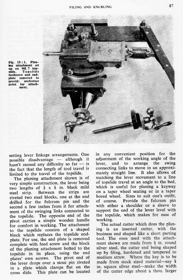
                                      I've found the original source for the slotter in Len Mason's "Using the small lathe"

                                      mason slotter.jpg

                                      Although originally published in 1963 I still find this book a useful source of information on workshop techniques.

                                      Hope this helps,

                                      Rod

                                      #511163
                                      Hopper
                                      Participant
                                        @hopper

                                        Thanks. I'll buy a copy. I have all the other grand masters of yore. Always a treasure trove.

                                        #511167
                                        Howard Lewis
                                        Participant
                                          @howardlewis46836

                                          Hopper,

                                          Once, I cut a small square hole for a scooter speedo drive, by holding a 1/8 toolbit in the tailstock, and racking the barrel to and fro (Having drilled a 1/8 hole and with 90 rotation of the chuck between cuts ) using the traverse screw, with the Tailstock locked to the bed.

                                          If you don't want to mess about with your Top Slide, I can recommend making the Peter Robinson Slotting Tool, using the casting from College Engineering. I added a grease nipple to the top of the casting, to lubricate and improve the "feel".

                                          It was designed for the Myford 7 Series, but after selling the ML7 , I made a riser block to use it on my BL12 – 24.

                                          You may nee to do something similar, if you want to use on your Drummond.

                                          Howard

                                          #511171
                                          John P
                                          Participant
                                            @johnp77052

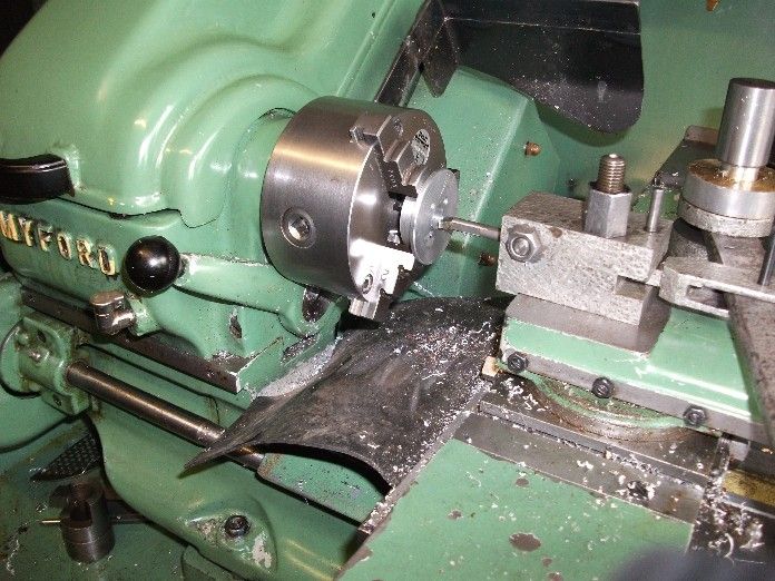
                                            The photo here shows this keyway slotting tool
                                            that was published in the Model engineer in the early
                                            nineties issue 3980 page 541 ,is available in the My
                                            Hobby store plans list as "Slotting attachment for the
                                            Myford super 7 lathe " plan no WE 68.
                                            Although similar to the Mason design is simpler to make
                                            and eliminates the shortcomings in his design ,the lever
                                            thrust position is directly behind the toolbit so there is no
                                            couple effect pushing the tool upwards in use .
                                            The topslide is only a guide for the tool, the tool block
                                            automatically indexes the cutting tool on centre
                                            height and the tooling is provided with reference for
                                            grinding the tool cutting edge.

                                            Johnkeyway slotter.jpg

                                            #511173
                                            John Haine
                                            Participant
                                              @johnhaine32865
                                              Posted by Hopper on 01/12/2020 10:43:50:

                                              Posted by John Haine on 01/12/2020 09:52:58:

                                              I've only had to do one keyway for which I used the lathe (S7) and fed with the rack. It was tedious but worked, in a pulley that I had to sleeve to fit a motor shaft when I added a VFD to my mill.

                                              I have wondered whether the leadscrew would be stronger than the rack – though tedious by hand, since my lathe has CNC one could write a bit of G code that simply drives the Z axis back and forth over the required distance and slowing adds X feed to put the cut on. The same thing might be done on a CNC mill. My lathe has the standard Acme leadscrew on Z.

                                              Could be a bit wearing on the old halfnuts I reckon.

                                              ………..

                                              Well, I wonder. One of the nice things about CNC is that the machine does all the boring work and you can do things that would be much too tedious manually. In this case you could use a very small feed per cut (obviously big enough that the tool actually cuts and doesn't rub) which would make the job impossibly tedious by hand.

                                              #511193
                                              Hopper
                                              Participant
                                                @hopper
                                                Posted by John Haine on 02/12/2020 09:42:15:

                                                Posted by Hopper on 01/12/2020 10:43:50:

                                                Posted by John Haine on 01/12/2020 09:52:58:

                                                I've only had to do one keyway for which I used the lathe (S7) and fed with the rack. It was tedious but worked, in a pulley that I had to sleeve to fit a motor shaft when I added a VFD to my mill.

                                                I have wondered whether the leadscrew would be stronger than the rack – though tedious by hand, since my lathe has CNC one could write a bit of G code that simply drives the Z axis back and forth over the required distance and slowing adds X feed to put the cut on. The same thing might be done on a CNC mill. My lathe has the standard Acme leadscrew on Z.

                                                Could be a bit wearing on the old halfnuts I reckon.

                                                ………..

                                                Well, I wonder. One of the nice things about CNC is that the machine does all the boring work and you can do things that would be much too tedious manually. In this case you could use a very small feed per cut (obviously big enough that the tool actually cuts and doesn't rub) which would make the job impossibly tedious by hand.

                                                Only one way to find out!

                                                One the line of getting away from tedious repetition by hand, I wonder if a modern update of one of the above mentioned slotting tools or topslide conversion could be converted to a powered version using a small drive motor and gearbox cheaply available these days on Aliexpress etc. They seem to have no end of automation components available, There must be something off the shelf that could do the job of powering a slotting tool or topslide conversion?

                                                #511194
                                                John Haine
                                                Participant
                                                  @johnhaine32865

                                                  **LINK**

                                                  Edited By JasonB on 02/12/2020 11:03:23

                                                  #511200
                                                  Hopper
                                                  Participant
                                                    @hopper
                                                    Posted by John Haine on 02/12/2020 10:51:49:

                                                    **LINK**

                                                    Edited By JasonB on 02/12/2020 11:03:23

                                                    ???? Did somebody swear?

                                                    #511517
                                                    Hopper
                                                    Participant
                                                      @hopper

                                                      Heres what I'm talking about:

                                                      Not sure what kind of old motor/gearbox unit he's driving it with. Could be a car starter motor? But looks like a capacitor on the side of it? His wiring is not exactly exemplary and should not be tried at home.

                                                      Anyhow, the modern version of the traditional lathe slotting tools could be made thus with the use of a stupid cheap automation motor and reduction gearbox from China, of which there are a million on sites such as Aliexpress etc. And I suppose that dreaded auction site. Just need to find the right one among the millions listed.

                                                      It would make quick work of cutting keyways in steel or cast iron gears and pulleys and could work for gear cutting too, with suitable indexing device on the lathe spindle.

                                                      Edited By Hopper on 04/12/2020 07:27:20

                                                    Viewing 25 posts - 26 through 50 (of 63 total)
                                                    • Please log in to reply to this topic. Registering is free and easy using the links on the menu at the top of this page.

                                                    Advert

                                                    Latest Replies

                                                    Home Forums General Questions Topics

                                                    Viewing 25 topics - 1 through 25 (of 25 total)
                                                    Viewing 25 topics - 1 through 25 (of 25 total)

                                                    View full reply list.

                                                    Advert

                                                    Newsletter Sign-up