How can I use this motor economically?

Advert

How can I use this motor economically?

Home Forums General Questions How can I use this motor economically?

Viewing 16 posts - 1 through 16 (of 16 total)
  • Author
    Posts
  • #462189
    Ian P
    Participant
      @ianp

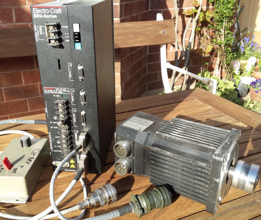
      I have been using this motor and its drive unit for several years in my linisher. Last week I unplugged it from the mains whilst I was having a tidy up and now it does not work. I have the full Electro-Craft manual for the drive and motor and the fault error number the drive shows is one that can only be repaired by board replacement followed by reconfiguring using software only given to authorised repair houses, in other words very expensive!

      As I do not need any of the servo functions but if possible would like to use it as a plain (hopefully variable speed) motor. I wondered whether it could be driven by a VFD, its rating plate describes it as an 'AC Motor' although it contains magnets on the rotor so its not a conventional induction motor.

      If it means anything to anyone here the motor is an 'H-4030-M-H-00AA'. Its continuously rated at 1.1KW 240V and runs up to 4000rpm. There are only 3 wires to the motor itself (plus another 20 or so to the shaft encoder)

      There are companies that supply refurbished drives (mostly in the USA) but at about $2000 not the route I want to take.

      Anybody know how else I could drive the this (and another two similar ones I have) motor?

      Ian P

      20200403_171209.jpg

      Advert
      #27254
      Ian P
      Participant
        @ianp

        Servo Drive unit is faulty

        #462192
        Clive Foster
        Participant
          @clivefoster55965

          Looks to be a bushless permanent magnet servo motor. If so you are stuffed without the drive box. It certainly won't run off a VFD.

          Many variations of this size and style of motor but most of the important bits are consistent for the whole range. Looks like the basic motor can be got fairly cheaply from China so I imagine the drive box can be found too. If its the Allen Bradley 1398 PDM 30 equivalent Google finds one source for £100 (ish) if you buy 100!

          Clive

          #462272
          Nick Clarke 3
          Participant
            @nickclarke3

            eBay has new 2800rpm 1.5HP 3 phase motors at well under £100. OK a bit slower that the present setup but throw in a vfd and would that be a more accessible and more economical way to go?

            #462286
            Frances IoM
            Participant
              @francesiom58905

              Does it have a small CR032 cell (or similar) to keep alive some memory feature – if so then if this cell had discharged from old age then possibly any mains driven standby power would have keep it alive but on unplugging this was lost along with some memory needed to start or run the controller – sometimes replacing such cells allows a factory default to be set up.

              #462292
              Ex contributor
              Participant
                @mgnbuk

                Looks like there is a repair service in the UK here

                I (or, more accurately, my employer ) typically pay around £600 + Vat to repair Fanuc AC servo drives of similar vintage & I would expect it would be a similar amount to repair your unit.

                Looking at a BRU series drive manual available online, it says that the setup parameters are stored in non volatile Ram or Eprom & makes no mention of a backup battery. The manual gives full motor specs & the motors seem to use a standard 5V encoder for feedback, so it may be possible to find a modern drive that will work with the motor – Kinco drives from Zapp Automation use encoders for feedback, so if your motor specs are similar to Kincos that might be an option though not cheap either (£550ish + Vat upwards ) – industrial stuff generally isn't hobbyist wallet friendly !

                From the date on the manual I found, your Electro Craft kit is around 25 years old, so maybe time to retire it ? Might be cheaper overall to stick the motors on Ebay & put any proceeds towards buying a replacement 3 phase motor & VFD for a simple linisher application.

                Nigel B.

                #462296
                Joseph Noci 1
                Participant
                  @josephnoci1
                  Posted by Clive Foster on 03/04/2020 21:48:46:

                  Looks to be a bushless permanent magnet servo motor. If so you are stuffed without the drive box. It certainly won't run off a VFD.

                  Clive

                  Not sure I agree with that..

                  The VFD is not aware of how the magnetic field arises in the rotor. It can be induced by the stator, or from permanent magnets.

                  If the Stator induces the field in the rotor, the motor is termed an induction motor, with attendant rotor slip to enable said induction.

                  If the rotor field is created, for example, an external DC supply through the rotor winding, then the motor is a Synchronous motor, ie, with little or no slip. This field can also arise form a permanent magnet rotor.

                  Almosy any Brushless motor, servo motor or otherwise can be driven by a VFD, assuming it is a 3 phase device, as most are. The key is to match the VFD RMS output voltage to the motor, relative to motor rotation speed and current flowing. Almost any half decent VFD allows that to be set. The is one exception though – VFD's that operate on the Vector principle should not be used with permanent magnet rotors – the vector VFD relies on the back-EMF to assist in rotor position determination, relative to the rotating stator magnetic field. The back-EMF detected is different for an induction motor, with rotor slip, and a synchronous motor, with respect to rotor position.

                  So, I would say, if you have a VFD ( non-vector type), hook it up the the motor windings, set the VFD max output voltage to around 80 or so to start, set max current to 1amp, and try it. If it over-currents without starting, increase the current to maybe 2amps – don't go higher just yet…

                  If is spins, you can open the envelope up , but watch the currents! Since you had the motor running previously, you will know what is 'sounds' like when happy – listen for that sound!

                  BEFORE DOING ANY OF THIS !!—

                  Check that there is no short between any motor winding and the motor body.

                  Connect the motor body to the same ground as the VFD is..

                  Why I suggest this can work? – Well I have done this on a few RC brushless motors, a notable one being an 8KW peak, 1KW RMS outrunner – it is about 160mm diameter and 120mm deep, max applied voltage is 120V, and does 5000RPM at 120V AC 3phase. I use it as a drive motor on a wood cutting spindle table.

                  The VFD I used is a 2KW YASKAWA.

                  Joe

                  #462320
                  Joseph Noci 1
                  Participant
                    @josephnoci1

                    Just dug out my notes I made when I played with this setup –

                    It triggered some memories…

                    Since the motor runs as a Synchronous motor, there is no slip, and so torque is not related to angular slip as in an induction motor, but to amplitude of the magnetic field. What this means is that if you exceed the torque at a given point, the motor will simply stall, and unlike a synchronous motor, will most likely not start up again, till you remove the supply and load, and restart. That stall condition can be catastrophic for the motor! The current will go high, and smoke may come out, hence my hint at keeping the current setting on the VFD as low as possible, while experimenting.

                    Also, I see from the notes, some of the low pole count motors did not run very smoothly either – the 4 pole RC motors were roughest, with some even cogging, stopping, and re-starting in reverse at low AC frequencies ( below 10hertz)

                    Joe


                    Joe

                    Edited By Joseph Noci 1 on 04/04/2020 15:33:37

                    #462322
                    Clive Foster
                    Participant
                      @clivefoster55965

                      Joseph

                      Thats interesting information about possibly running such motors on a VFD.

                      Hafta admit that I assumed the need to run synchronously with no automatic relationship between angular slip and torque made it essentially impossible to drive such motors by open loop style controllers such as a VFD. Obviously if the motor can be bought into synchronous lock with the VFD it will run and keep running but this would seem to be very much a knife edge, balancing a spinning plate on a stick, kind of thing. Any change in load being seemingly sufficient to pull the motor far enough out of sync with the drive to stall.

                      I always thought that the clearly non trivial task of dealing with such things was the main reason why the drives are so expensive.

                      Clearly the real world isn't quite that sensitive. But its not something I'd care to try.

                      Clive

                      #462381
                      Ian P
                      Participant
                        @ianp

                        Thanks for the info and suggestions, I know in my heart that making use of this type of motor without a suitable servo drive is not possible and its unrealistic of me to expect to find an economic way of doing it.

                        As mentioned the 'personality' and the configuration of the drive is stored in a eeprom so no battery involved, why this became corrupted just by unplugging and reconnecting to the mains is a mystery as its something I have done frequently. Using it to drive a linisher is almost a criminal waste of technology but the motor and drive were lying around spare when the original grotty induction motor burnt out. I have the customer version of the Windows 'BRU Master' software which allows configuring all the drive parameters but when I connect it to the drive it communicates but then reports the corrupted NV memory (as does the drives own error number).

                        I do have a second drive unit and motor which are currently working and fitted to a X1 size mill, I very rarely use it so could borrow the drive off that but as suggested it would probably make more sense to fit an induction motor with VFD and then sell the servo motors and drives I have (used kit seems to fetch high prices especially in the USA).

                        Joe's comments and recollections about the motor only running synchronously make it totally unsuitable as a machine power source, I could imagine with determination it would be possible to incorporate a feedback system and then drive with a VFD buts it not something I could tackle.

                        Just to mention as an item of interest. I control the motor speed and direction using the drive's analogue input (+/-10V) with a pot and toggle switch. Even at 4000rpm clicking the switch between forward/reverse is utterly drama free with the motor changing direction almost imperceptibly. If I had the expertise then using one of these as a direct drive lathe spindle motor would be ideal for ELS purposes.

                        Ian P

                        #462382
                        DC31k
                        Participant
                          @dc31k

                          Deep inside the SIM card in my head, there is something that says the LinuxCNC people, before the days it was called LinuxCNC, were developing an open source servo motor driver.

                          Unfortunately, that is all I know.

                          #462388
                          Robert Atkinson 2
                          Participant
                            @robertatkinson2

                            The only resonable option to run the motor would be a cheap brushless DC motor driver if the motor has suitable hall sensors. It's a lot of messing about though. It can be hard enough when you have the drive and motor data and the are supposed to be compatible

                            My suggestion is list it on ebay as working motor and faulty amplifier. do a search for completed listing (do it on ebay.com to include USA) to get an idea what they have old for. You may get enough to buy a 3 phase motor and VFD.

                            Robert G8RPI.

                            #462392
                            Ian P
                            Participant
                              @ianp

                              Thanks Robert, I'm not sure if this motor has integral Hall sensors but even if it did there is quite a lot of work (and some expense) to get it running. Even then it would be a fairly dumb system compared to what features even a cheap VFD has (accel/decel etc etc) so. Since I have three of the motors and two drives (one faulty) putting them on eBay is what I think I will do.

                              I thought it might be best to wait until things get nearer to normal but I've just looked at eBay help pages and surprisingly they say its mostly business as usual.

                              #462408
                              Joseph Noci 1
                              Participant
                                @josephnoci1

                                Unlikely to have hall sensors as there is an encoder used by the servo controller – that would give the controller all the needed shaft position info for proper coil phasing, esp since Ian mentions 'many' wires to the encoder, so most likely an absolute position encoder.

                                Joe

                                ps – I can never leave these things alone – always needed to know what is 'inside'…I would still try a VFD, if you have one available, set up in 'safe mode'… ( dissected my 6 transistor radio birthday gift at 8 years old – to see 'how' it worked..did not manage to make it work as a radio again, but did make a usable intercom out of it,connected with a long wire pair to a similar 'radio' at my buddies place next door..)

                                #462446
                                Ex contributor
                                Participant
                                  @mgnbuk

                                  Unlikely to have hall sensors

                                  I would have expected that as well, but reference to the manual does show Hall A,B & C outputs in the encoder connector at the motor, as well as the usuall A. /A, B, /B. I, /I of an incremental encoder, 5V & ground (two connections for each) and a thermal switch. There is also a asingle output called "ABS" which is described as being an absolute encoder – though how that is achieved through a single pin I don't know.

                                  Strangely the Hall signals do not appear to be used by the BRU amplifier, as they do not appear on the amplifier encoder input port pinout. The copy of the manual I found is here

                                  "Universal" drives are available – one that springs to mind is the Control Techniques Unidrive, which can be connected to pretty well any type of AC motor, with or without feedback. CT also used to do a Vector drive that used a standard squirrel cage 3 phase motor with an encoder fitted & an independant axial blower. I used one of these many years ago as a spindle drive on a Cincinatti NC drilling machine retrofit, but can't recall anything specific about it. I seem to recall that Siemens Simodrive 611 use the same output modules to drive synchronous or asynchronous motors, but they may use different interface cards to suit the type of motor – I try to avoid anything Siemens unless I absolutely have to & have not had to specify or commision one of these systems from scratch.

                                  Nigel B.

                                  #462614
                                  Ian P
                                  Participant
                                    @ianp

                                    I have 'parked' the servo motors and drive for the time being and am fitting a standard motor and VFD to the linisher. There are no Hall sensors in this motor particular motor, The picture is the inside of the motor terminal box and the only wires exiting the motor itself are the three thick wires plus two white ones (probably the thermal sensor).

                                    The manual linked to is a shorter version of the one I have but is essentially correct.

                                    Ian P

                                  Viewing 16 posts - 1 through 16 (of 16 total)
                                  • Please log in to reply to this topic. Registering is free and easy using the links on the menu at the top of this page.

                                  Advert

                                  Latest Replies

                                  Home Forums General Questions Topics

                                  Viewing 25 topics - 1 through 25 (of 25 total)
                                  Viewing 25 topics - 1 through 25 (of 25 total)

                                  View full reply list.

                                  Advert

                                  Newsletter Sign-up