Feeds and Speeds! 0.4mm milling cutters…

Advert

Feeds and Speeds! 0.4mm milling cutters…

Home Forums Beginners questions Feeds and Speeds! 0.4mm milling cutters…

Viewing 17 posts - 1 through 17 (of 17 total)
  • Author
    Posts
  • #9687
    Steve Withnell
    Participant
      @stevewithnell34426
      Advert
      #411562
      Steve Withnell
      Participant
        @stevewithnell34426

        I've just bought some 0.4mm milling cutters, to try to cut some isolation tracks in a PCB. Now I know 0.4mm is pretty small, but cutter in hand, it's scary small.

        Max spindle speed is 7000rpm – so given I use a 0.04mm depth of cut – any views on what the maximum cutting speed should be? My calculator says 50mm per minute, but these things look like they will shatter with a hard stare!

        I know 7000rpm is way short for a cutter of that diameter, but I need to work with what I have.

        The other question would be plunge rates – not only for the 0.4mm cutter, but any cutter. It's something I've never worried about with a manual machine, but no 'feel' with a little CNC means I do need to think about it now.

        Regards

        Steve

        #411564
        JasonB
        Moderator
          @jasonb

          How many flutes?

          ranping would be safer than plunging.

          #411565
          Anonymous

            Not enough information: HSS or carbide, how many flutes and centre cutting or not? What's mind boggling is how they make and grind the cutter in the first place.

            For "plunging" I use a third to a half of the normal feedrate, on the grounds that only one edge will be cutting all the way to the centre. In reality I don't plunge straight down; I program either a ramp or helix that means the centre has a chance to cut rather than rub.

            Andrew

            #411570
            Nick Hulme
            Participant
              @nickhulme30114

              Cutter geometry is required for calculation, if it's 2mm flute length on a 1/8 shank that may not be wide of the mark, it's always a plan to start with 50% of the suggested feed rate as all guides will assume that everything about your machine is ideal for the job.

              #411571
              John Haine
              Participant
                @johnhaine32865

                Sorry to rain on your parade, but better cutters to use are engraving cutters. You can get a pack of 10 TC cutters for not a lot from eBay. Look for LineGrinder SW on Google, I recall it has a lot of useful info about which cutters to use and the process. Run as fast as you can in the spindle – I used 6000 rpm, feeding at 100 mm/min and didn't break a cutter.

                #411572
                blowlamp
                Participant
                  @blowlamp
                  Posted by John Haine on 29/05/2019 20:18:15:

                  Sorry to rain on your parade, but better cutters to use are engraving cutters. You can get a pack of 10 TC cutters for not a lot from eBay. Look for LineGrinder SW on Google, I recall it has a lot of useful info about which cutters to use and the process. Run as fast as you can in the spindle – I used 6000 rpm, feeding at 100 mm/min and didn't break a cutter.

                  Ditto. Beat me to it. smiley

                  They are much stronger due to being tapered.

                  Martin.

                  #411636
                  Alan Wood 4
                  Participant
                    @alanwood4

                    Having spent some time evolving my pcb milling process here are a few comments.

                    I use FlatCam to create the CNC code from Gerber and Excellon files out of GSpark. FlatCam was the first program I tried and it does everything I need without looking further. It allows default start up and shut down GCodes to be embedded in the export code to the mill (in my case a Tormach PCNC440).

                    I run at 10,000 rpm (maximum possible on the 440) and at 150mm per minute with a 5.1 thou cutter. While I ramp and spiral in when cutting metal I rarely have the real estate on my pcbs to allow this luxury. I dive straight in and cut and it has not been an issue.

                    I found that tapered engraving bits to be fine providing the pcb material could be clamped flat. If the material is not flat then variations in cut depth result which in turn leads to a wider cut through the copper (think about the geometry). I tried 10 degree cutters to minimise this and found them to be very fragile. If tracking is wide this may not be an issue.

                    I subsequently found proper fine milling bits from Think & Tinker that which are parallel for the first section and then taper up. They can be supplied with collars so collet mounting is repeatable. They are expensive but are good if you need to go to fine detail.

                    I tried various clamping methods for the pcb material to try to eliminate the bow. Single sided board is the worst as having the copper on one side causes a 'surface tension' style bowing from the laminating process. In the end I solved this by designing and making a simple vacuum table which runs off the 'hoover', This was an amazing success for a finger in the air idea. The Fusion 360 file is available if anyone who wants to try it.

                    The vacuum table while solving the clamping does mean it is not prudent to drill holes all the way through the pcb and potentially damage the vacuum table surface and or damage the carbide pcb drills. I therefore drill to almost break through and then go round the board afterwards with my high speed bench drill. With the centres already spotted it is a quick process.

                    One option that could be used but not tried as yet is to put 'gaffa' tape or similar on the pcb back side to provide a finite spacer and allow some additional depth for through drilling.

                    Finally I use mist coolant (via a Fog Buster) when milling the boards. This is the same as I use for metal machining (Qualichem Xtreme 250C). It helps the finish, protects the tool and also damps down the dust.

                    The finish straight off the mill is sometimes not too pretty but after a gentle rub over with fine wet and dry looks excellent. With a 5 thou tip I can cut very fine SMD tracking.

                    After the wet and dry, while the board has a bright clean untarnished finish, rub over with flux paste and then run a wide bit hot soldering iron quickly over the tracking while feeding fine solder to it. Once you have got the knack you can get a good tinned finish. Clean the flux residue off afterwards with thinners and then wash with Swarfega or similar hand cleaner to get a bright finish on the tin (yes I know it sounds weird but try it).

                    There is a lot more detailed waffle and pictures of my experiments at Woody's Workshop.

                    I hope that helps someone somewhere to get a working result.

                    #411780
                    Steve Withnell
                    Participant
                      @stevewithnell34426

                      Well I got that one wrong – turns out they are not cutters but drills! So I do need to look at getting some engraving cutters…

                      I'll also take a look at ramping, I've seen the function in the CUT2D screens but not tried it out yet.

                      Next stop Woody's Workshop!

                      Regards

                      Steve

                      #411797
                      Anonymous
                        Posted by Steve Withnell on 30/05/2019 21:18:21:

                        …………turns out they are not cutters but drills!

                        Doooh!

                        Some years ago I spent quite a while trying engraving cutters of assorted styles in aluminium on my CNC mill. I didn't have much success; they all broke sooner or later. I came to the conclusion that the top speed of 5000 rpm simply wasn't high enough.

                        Andrew

                        #411819
                        Joseph Noci 1
                        Participant
                          @josephnoci1


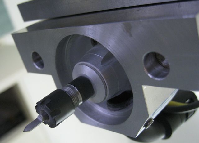
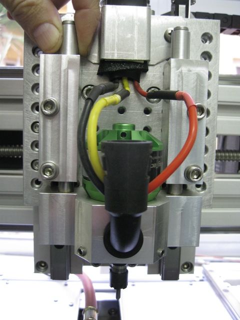
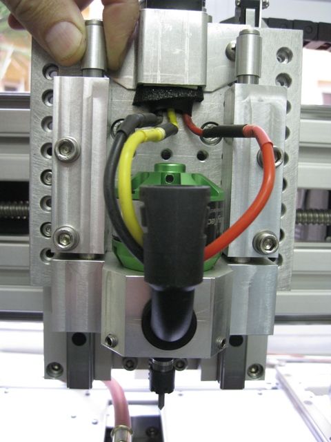
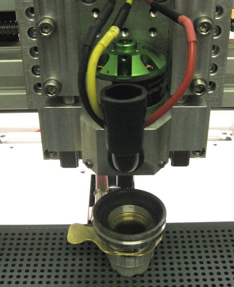
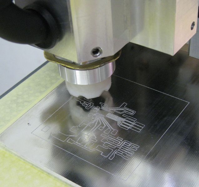
                          As said, rather use a D engraving bit. I have great success with them. I built this CNC engraver specifically for PCB Isolation routing. The spindle motor is an RC Outrunner, turning at about 30.000rpm.

                          The cutter penetrates about 40 to 45um( the copper is around 35um on my FR4 PCB).

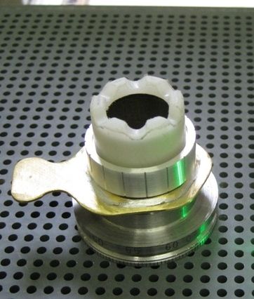
                          The trick with these engraving cutters is that the PCB has to be flat, and co-planar, else the tapered cutter cuts different widths as it penetrates the copper more or less. I gave up on trying to engrave with PCB just mounted 'flat' on the table – it was never flat or co-planar. Some cad packages can do auto-leveling, and you may have success that way. I made a floating head for my machine – floating on a teflon foot, with vacuum cleaning away the cuttings inside the foot, to ensure it always rides on the copper.

                          I also tried a vacuum table, but the PCB still is never flat enough – 20um makes a huge difference, and 20um is very small…

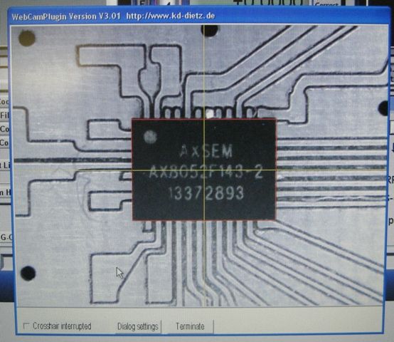
                          The PCB in the photo below has a pad spacing of 0.5mm. Tracks are 0.3mm wide, with 0.1mm isolation cut away.

                          The engraved finish is very good – no burrs, with some cleanup required of fine slivers sometimes left isolated between tracks.


                          EDIT: 

                          Forgot to add – feed is straight down into the material ( only 45um into copper..) @ 400mm/min and cutting @ 600mm/min in X and Y. I can achieve those speeds as the machine is small, and VERY rigid. You would probably have to go down to around 40 to 80mm/min with a spindle speed around 6000rpm…

                          Cutter geometry is VERY critical. The cutting edge and cutter relief makes the difference between a terrible burred edge, and a clean smooth cut. Cutter relief at the very tip of a 10degree engraving cutter is not a trivial exercise to achieve, so get quality cutters if you can. I bought many 10's of cutters from banggood – 10 in a pack, and typically get 3 to 5 in a psck that work well – the rest vary from useless to 'good enough' for rough boards. Then I grind them again on my small T&C grinder, and after 2 or three grind attempts, I have another good set..

                          I use cutters with included angles from 10deg up to 45deg – they all do the job. For very fine tracks and pad spacing you would need the 10deg cutters. I have done down to 0.25mm pad spacing, with tracks of 0.12mm width..

                          Joe

                          spindle1.jpg

                          spindle2.jpg

                          nose and tool1.jpg

                          Floating head lowered

                          head down.jpg

                          And Raised a few mm

                          head up.jpg


                          floating foot.jpg


                          PCB Being Engraved


                          Small IC placed on engraved PCB


                          Edited By Joseph Noci 1 on 30/05/2019 23:42:06

                          #411966
                          Steve Withnell
                          Participant
                            @stevewithnell34426

                            Looks fantastic Joseph!

                            One other poster had a strong recommend for 60 deg cutters – sounds like you are at the other end of the range with 10 deg cutters?

                            The PCB I'm looking to cut is pretty exotic stuff – RT6035HTC. As you say, the cladding is 35um.

                            What I've just discovered is the substrate is ceramic loaded with PTFE! Ceramic doesn't sound good at all, but worth a try. Otherwise its going to have to be back to chemi-etch which I really want to avoid.

                            The board is for a 300Watt 2.4GHz amplifier (think solid state microwave) so needs excellent heat tolerance hence the ceramic.

                            Steve

                            #411968
                            SillyOldDuffer
                            Moderator
                              @sillyoldduffer

                              Posted by Steve Withnell on 31/05/2019 18:08:53:.

                              The board is for a 300Watt 2.4GHz amplifier …

                              Steve

                              Just what I need to swat my neighbours Wifi!

                              devil

                              #411983
                              Joseph Noci 1
                              Participant
                                @josephnoci1
                                Posted by Steve Withnell on 31/05/2019 18:08:53:

                                Looks fantastic Joseph!

                                One other poster had a strong recommend for 60 deg cutters – sounds like you are at the other end of the range with 10 deg cutters?

                                The PCB I'm looking to cut is pretty exotic stuff – RT6035HTC. As you say, the cladding is 35um.

                                What I've just discovered is the substrate is ceramic loaded with PTFE! Ceramic doesn't sound good at all, but worth a try. Otherwise its going to have to be back to chemi-etch which I really want to avoid.

                                The board is for a 300Watt 2.4GHz amplifier (think solid state microwave) so needs excellent heat tolerance hence the ceramic.

                                Steve

                                Hi Steve. I am not really advocating specific included cutter angles at all – My approach is to use the largest angle possible, in keeping with the complexity of the board to be engraved. If your flavour is 0.1" pin spacing with one track between pins, then a 45deg cutter will do fine. The advantage of wider angle cutters is the robustness of the tip improves, and wear is less. Control over width of engraving does suffer though. A 45deg cutter will cut a much wider groove for smaller depth increase than will a 10 degree cutter. So a lot depends on how well you can control cutting depth, how rigid the machine is, etc. A floating head controls depth just fine, assuming a good vacuum system for chip removal so that the float rides on clean BURR FREE (!) PCB.

                                RT6035HTC is a Rogers laminate. It is still quite flexible, ie, it is not like a ceramic kitchen tile….The ceramic is added not really to increase heat resistance but to increase the dielectric constant, so that strip-line lengths are reduced, ie, wavelength of RF propagation reduces, so stripline dimension reduce ( Wavelength = Wavelength in free space / Sq Root of the dielectric constant). PTFE already has a constant around 4 ( effectively halving the propagation wavelength)or so, and the ceramic can take this up to 7 or 8 quite easily.

                                Engraving this material is in fact a lot easier than normal FR4…The laminate is not glass hard as the ceramic powder is embedded in PTFE, so the cutter penetrates and cuts quite easily – easier than in fibreglass. The problem with RF circuits on this type of laminate is that you normally remove large areas of copper, ie, it is not just track isolation as in normal digital or analogue circuitry. Striplines that form the inductors and capacitors in uWave RF PCB circuitry have very critical dimension tolerances and proximity to other conducting surfaces, worsening with increase in frequency..

                                And removing large copper areas on a laminate with even a 90deg cutter is tedious as best…You would need to use carbide flat end mills for that, and depth control is critical if you wish to maintain your stripline size computations…

                                One of my Career Lives was in uWave RF design – up to 76GHz, so experience has burnt many of my fingers…

                                regards

                                Joe.

                                PS – I presume this is for a radio Amateur application? 300 watts in the 2.4GHz ISM band may otherwise land you in none-to-tepid water…

                                #411987
                                Alan Wood 4
                                Participant
                                  @alanwood4

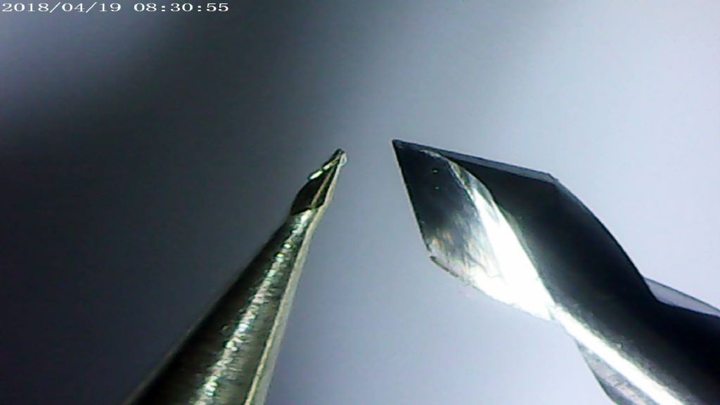
                                  Attached image are two examples of the Think & Tinker bits.

                                  Left hand one is their 15 degree 2 flute tapered stub ZrN coated and right hand one is 60 degree mechanical etching bit.

                                  Both have 5 thou tips.

                                  Sorry about the image but was struggling at this magnification.

                                  I prefer the left hand one as the taper is so slight that it eliminates width of track variations on my vacuum table.

                                  Joe clearly has much more experience than me on the subject. I have seen his set up first hand.

                                  My business life (W&D) also revolved round RF comms where we used a LPKF machine for PCB prototyping on Rogers substrates including brass backed.

                                  Alanpic002.jpg

                                  #411997
                                  Bazyle
                                  Participant
                                    @bazyle

                                    About 20 years ago we got a pcb miller at work that seemed cutting edge tech to us then. Package of software and a machine like the now common far eastern 'CNC Mills' on ebay but probably from Farnel or equivalent. It just whizzed around at several inches per min and the motor was nothing special, more like a dremel. I can't remember any details about the cutter but I'd expect such things still to be around so perhaps searching that kind of supplier would find cutters specific to this sort of operation.

                                    Lots of RF engineers here. laugh I was mostly >6GHz for 20 years on satellites and airborne EW.

                                    #412786
                                    Steve Withnell
                                    Participant
                                      @stevewithnell34426
                                      Posted by Joseph Noci 1 on 31/05/2019 20:19:00:

                                      Posted by Steve Withnell on 31/05/2019 18:08:53:

                                      Looks fantastic Joseph!

                                      One other poster had a strong recommend for 60 deg cutters – sounds like you are at the other end of the range with 10 deg cutters?

                                      The PCB I'm looking to cut is pretty exotic stuff – RT6035HTC. As you say, the cladding is 35um.

                                      What I've just discovered is the substrate is ceramic loaded with PTFE! Ceramic doesn't sound good at all, but worth a try. Otherwise its going to have to be back to chemi-etch which I really want to avoid.

                                      The board is for a 300Watt 2.4GHz amplifier (think solid state microwave) so needs excellent heat tolerance hence the ceramic.

                                      Steve

                                      Hi Steve. I am not really advocating specific included cutter angles at all – My approach is to use the largest angle possible, in keeping with the complexity of the board to be engraved. If your flavour is 0.1" pin spacing with one track between pins, then a 45deg cutter will do fine. The advantage of wider angle cutters is the robustness of the tip improves, and wear is less. Control over width of engraving does suffer though. A 45deg cutter will cut a much wider groove for smaller depth increase than will a 10 degree cutter. So a lot depends on how well you can control cutting depth, how rigid the machine is, etc. A floating head controls depth just fine, assuming a good vacuum system for chip removal so that the float rides on clean BURR FREE (!) PCB.

                                      RT6035HTC is a Rogers laminate. It is still quite flexible, ie, it is not like a ceramic kitchen tile….The ceramic is added not really to increase heat resistance but to increase the dielectric constant, so that strip-line lengths are reduced, ie, wavelength of RF propagation reduces, so stripline dimension reduce ( Wavelength = Wavelength in free space / Sq Root of the dielectric constant). PTFE already has a constant around 4 ( effectively halving the propagation wavelength)or so, and the ceramic can take this up to 7 or 8 quite easily.

                                      Engraving this material is in fact a lot easier than normal FR4…The laminate is not glass hard as the ceramic powder is embedded in PTFE, so the cutter penetrates and cuts quite easily – easier than in fibreglass. The problem with RF circuits on this type of laminate is that you normally remove large areas of copper, ie, it is not just track isolation as in normal digital or analogue circuitry. Striplines that form the inductors and capacitors in uWave RF PCB circuitry have very critical dimension tolerances and proximity to other conducting surfaces, worsening with increase in frequency..

                                      And removing large copper areas on a laminate with even a 90deg cutter is tedious as best…You would need to use carbide flat end mills for that, and depth control is critical if you wish to maintain your stripline size computations…

                                      One of my Career Lives was in uWave RF design – up to 76GHz, so experience has burnt many of my fingers…

                                      regards

                                      Joe.

                                      PS – I presume this is for a radio Amateur application? 300 watts in the 2.4GHz ISM band may otherwise land you in none-to-tepid water…

                                      Interesting! Yes it is for an Amateur Radio application – Oscar 100 satellite. Not me by the way, just enjoy building the stuff. I managed to finish a 2.4Ghz filter to sit in front of the PA which looks like it is proving close on 50dB suppression of the mixer signal whilst the insertion loss is c0.5dB at the centre frequency.

                                      I've been playing with FR4 and with a brand new 5mm carbide cutter, the large areas skim off really nicely. I've experimented with 2mm, 1mm and 0.5mm milling cutters and getting good results. The is no requirement for 0.1inch matrix for this board. My 'customer' has simplified the PCB design, so I might get away with 1mm cutter for the edge of the tracks and a 5mm cutter to remove the waste areas.

                                      Given 5G is targeting 76GHz then there will be plenty of work to keep you busy! Lancaster Uni have developed some backhaul radio systems at 94GHz. for 5G, so lots of interesting stuff going on.

                                      Regards

                                      Steve

                                    Viewing 17 posts - 1 through 17 (of 17 total)
                                    • Please log in to reply to this topic. Registering is free and easy using the links on the menu at the top of this page.

                                    Advert

                                    Latest Replies

                                    Home Forums Beginners questions Topics

                                    Viewing 25 topics - 1 through 25 (of 25 total)
                                    Viewing 25 topics - 1 through 25 (of 25 total)

                                    View full reply list.

                                    Advert

                                    Newsletter Sign-up