Building Bernard Tekippe’s Precision Regulator
Building Bernard Tekippe’s Precision Regulator
- This topic has 146 replies, 14 voices, and was last updated 18 August 2025 at 03:37 by
 Michael Gilligan.


- Please log in to reply to this topic. Registering is free and easy using the links on the menu at the top of this page.
Latest Replies
-
- Topic
- Voices
- Last Post
-
-
Making Unimat DB/SL Steadies
1
2
Started by:
Andy Carlson
in: Workshop Techniques
- 12
-
18 August 2025 at 23:44
Emgee
-
The stand alone weight for tower clock
Started by:
dk0
in: Clocks and Scientific Instruments
- 6
-
18 August 2025 at 22:34
duncan webster 1
-
Greatest Model Engineer
Started by:
Juddy
in: The Tea Room
- 7
-
18 August 2025 at 21:39
Buffer
-
Cheap DRO
Started by:
Steve355
in: General Questions
- 11
-
18 August 2025 at 20:20
Steve355
-
Harold Hall – 1933 -2024
Started by:
Neil Wyatt
in: Website Announcements
- 13
-
18 August 2025 at 18:24
Vic
-
My week this week! My workshop videos
1
2
…
11
12
Started by:
Phil Whitley
in: The Tea Room
- 16
-
18 August 2025 at 17:20
vic newey
-
Who’s to be trusted ?
1
2
Started by:
Michael Gilligan
in: Electronics in the Workshop
- 18
-
18 August 2025 at 16:01
HOWARDT
-
Steam driven air pump for brakes
Started by:
Werner Schleidt
in: Locomotives
- 9
-
18 August 2025 at 13:13
parovoz
-
NU tool milling machine
Started by:
joseph tatler
in: Manual machine tools
- 7
-
18 August 2025 at 11:11
Martin Connelly
-
Opposed Piston Engines
1
2
Started by:
Richard Simpson
in: The Tea Room
- 11
-
18 August 2025 at 10:48
JasonB
-
Model Engineer Magazine Collection
Started by:
mfengine1
in: Books
- 10
-
18 August 2025 at 09:33
bcaddle62
-
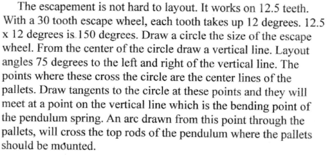
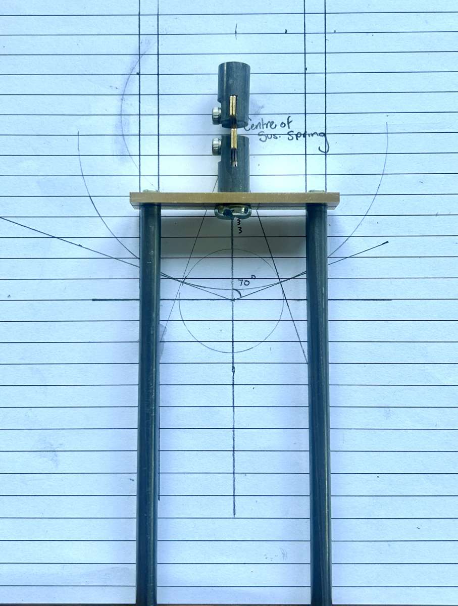
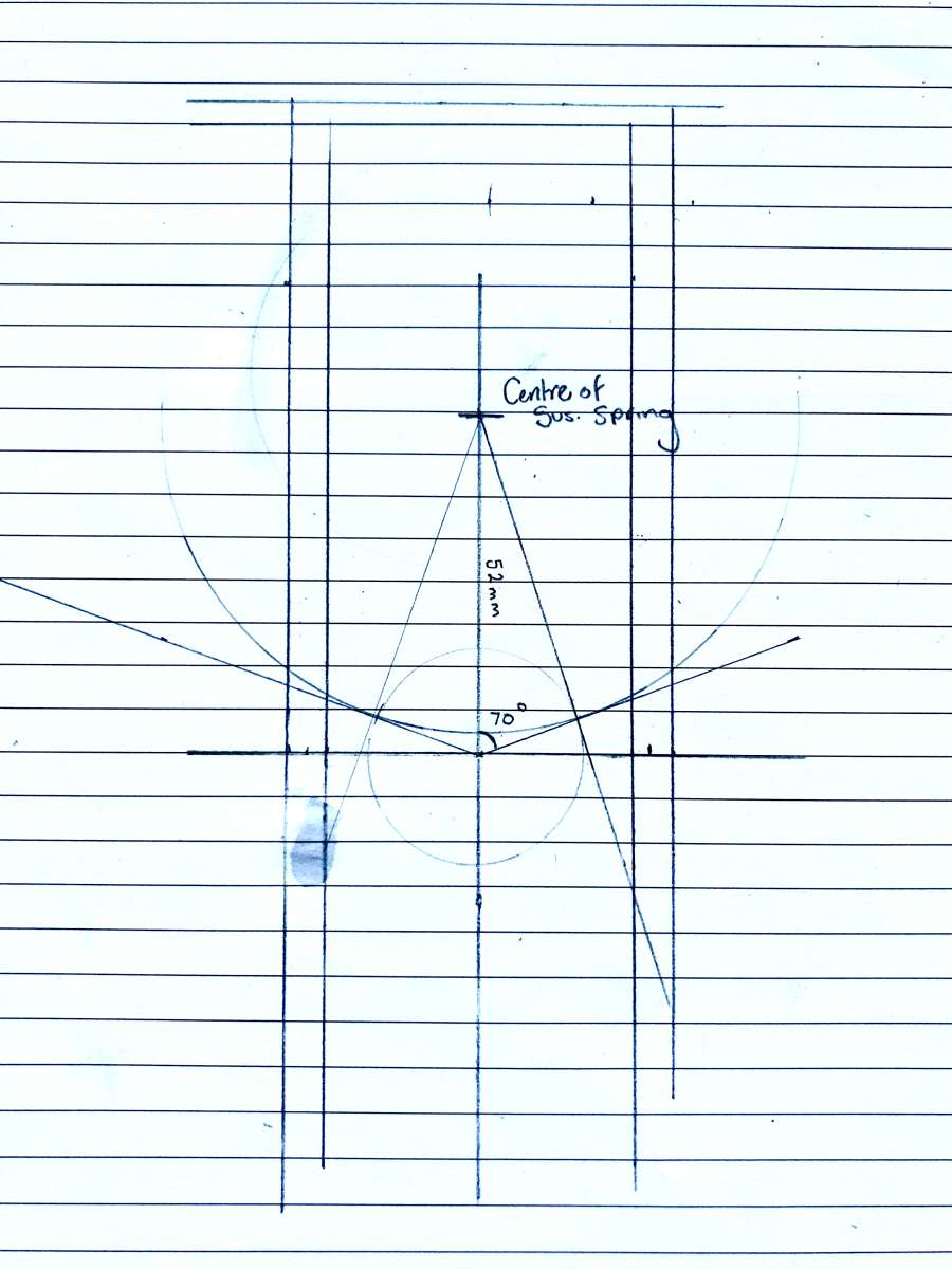
Building Bernard Tekippe’s Precision Regulator
1
2
…
5
6
Started by:
Chris Raynerd 2
in: Clocks and Scientific Instruments
- 14
-
18 August 2025 at 03:37
Michael Gilligan
-
Herbert B Drill Pulley and Lubrication
Started by:
Steve Hunt
in: Help and Assistance! (Offered or Wanted)
- 3
-
18 August 2025 at 00:24
Steve Hunt
-
3 phase supply (again)
1
2
3
Started by:
colin hamilton
in: General Questions
- 21
-
17 August 2025 at 19:33
mark costello 1
-
Vickers Inverted Engine
1
2
3
Started by:
JasonB
in: Stationary engines
- 11
-
17 August 2025 at 19:29
JasonB
-
Henry Buckeldee
Started by:
Michael Gilligan
in: The Tea Room
- 1
-
17 August 2025 at 16:03
Michael Gilligan
-
Old Magazines – Countrymans Steam Suffolk Dredging Tractor
Started by:
Tris Summers
in: The Tea Room
- 1
-
17 August 2025 at 15:49
Tris Summers
-
Open Day at Warrington
Started by:
duncan webster 1
in: The Tea Room
- 2
-
17 August 2025 at 14:52
Martin Kyte
-
Raab Style Heibluftmotor
Started by:
JasonB
in: Miscellaneous models
- 3
-
17 August 2025 at 13:05
JasonB
-
Linear Dividing
Started by:
Michael Gilligan
in: Clocks and Scientific Instruments
- 4
-
17 August 2025 at 13:02
Martin Johnson 1
-
Arc Euro Trade Ltd.
1
2
3
Started by:
Ketan Swali
in: General Questions
- 56
-
16 August 2025 at 21:54
Lathejack
-
MicroSet3 timer – help to set for tacho
Started by:
gerry madden
in: Electronics in the Workshop
- 2
-
16 August 2025 at 19:41
gerry madden
-
New member – mid 50s Zyto Lathe
Started by:
peterrivers
in: Introduce Yourself – New members start here!
- 5
-
16 August 2025 at 16:06
peterrivers
-
Reference lines for dimensions – Fusion 360
Started by:
John McCulla
in: CAD – Technical drawing & design
- 5
-
16 August 2025 at 13:59
blowlamp
-
Using Old Bits and Pieces
Started by:
Richard Simpson
in: Model Boats
- 11
-
16 August 2025 at 13:27
Colin Bishop
-
Making Unimat DB/SL Steadies
1
2


