Boring Bars.

Advert

Boring Bars.

Home Forums Workshop Tools and Tooling Boring Bars.

Viewing 25 posts - 26 through 50 (of 51 total)
  • Author
    Posts
  • #222492
    KWIL
    Participant
      @kwil

      Dorian Tools Inc

      Advert
      #222495
      GoCreate
      Participant
        @gocreate

        Yes, Dorian tools Inc

        Clearly there are various types of carbide boring bars and recommendations from various manufacturers.

        Of course these recommendations are relative to an industrial setting where production rate and tool performance are paramount. Maybe not so relevant in a home workshop however, the OP does report some observed benefits of his set up thus it's worth consideration.

        Nigel

        Nigel

        #222499
        ega
        Participant
          @ega

          Thanks to KWIL and tractionengine42.

          The Dorian document seems to be particularly to do with deep holes but, FWIW, I agree with the latter's comments.

          #222505
          ega
          Participant
            @ega

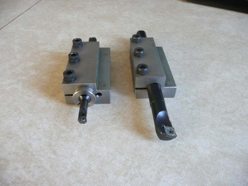
            Further down the Dorian document is a better view of their favoured split collar. A refinement on this was used by GHT as seen on the left in my photo ie a small stress- relieving hole; the other holder is a simpler version without the eccentric bush seen on the left. Proponents of other methods sometimes ask what the standard flats on the bar are for, if not for clamping? The flats do facilitate other methods but in my case the top flat just serves as a reference to the correct radial positioning of the bar in the holder; I have added a cross hole in the smaller bar which takes a tommy/sighting bar for setting the position.

            p1030657.jpg

            Edited By ega on 25/01/2016 11:06:21

            #222579
            Raymond Anderson
            Participant
              @raymondanderson34407

              At last there are folks on here that understand the concept of "Rigidity ". Im not saying use my method, only showing my preferred method. Folks are free to use whatever method suits them. The system shown in ega's pic is excellent,. I like that. and it would be even more rigid were it held in a solid toolblock. The whole concept of split sleeves is that it maximises the contact area around the bar rather than relying on screws. In some of my sleeves that are not split the bar is held by 4 M8 grub screws but each sleeve is bored to a precise fit for the specific bar. and those sleeves are used on my steel shank bars split sleeves for the Carbide ones. Screws directly on Carbide are only point loading stress risers, nothing more.

              some one earlier said that Sandvik Coromant show bars being held by screws, well, that may be, but it is not that firms preferred method and that shows steel bars not carbide, because going through their vast catalogue Sandvik dont make Carbide bars with flats, all their Carbide bars are cylindrical shank.

              There are some on here that are too quick to criticize systems that they have never used and maybe dont even understand . Well thank christ im not so "offhand " as that.

              Goodnight M, Ps, ever though of applying for a job in a circus ? you appear to have all the qualities needed.

              #222581
              JasonB
              Moderator
                @jasonb

                The other method that I've not seen mentioned here that I occasionally use for small round bars is a slit square like this as I only have a couple of V botton toolholders which tend to be kept set on height for their own bar. Just goes in a spare flat bottom tool holder and the screws bear on the top.

                #222584
                Emgee
                Participant
                  @emgee

                  I use the square bar method in Jason's picture, clamp the material in the toolpost and drill and ream from the chuck ensures an accurate bore for a round tool, slit after reaming.

                  In a rotary tool turret on a cnc lathe I use the round style, slit but screw clamped on the collet od, not the tool.

                  Emgee

                  #222585
                  Raymond Anderson
                  Participant
                    @raymondanderson34407

                    For anyone interested, http://americanmachinist.com/machining-cutting/cutting-tool-applications-chapter-10-boring-operations-and-machines. [The section entitled Boring bar clamping ] I'm not sure if this is the correct way to post a link, so apologies if it's not.

                    Jason, the pic in you're link looks the ticket. That will give a fine large area of shank to be clamped. and will result in increased rigidity.

                    #222588
                    Raymond Anderson
                    Participant
                      @raymondanderson34407

                      Emgee, The split collet /sleeve you mention is the same as the one shown in one of me pics [ If I get you correctly ]

                      #222604
                      Emgee
                      Participant
                        @emgee

                        Raymond, picture of my tool turret, boring tool fitted to 1 socket ready for use. I use brass collets made to suit the tool whether a drill, boring bar or reamer. There are 2 M6 grub screws to lock the split collet in place, these can be seen in the pic. I mill a flat where the screws bear on (90 deg to the slit) so any burr does not prevent collet removal.

                        Emgee

                        .short boring tool.jpg

                        #222605
                        Gray62
                        Participant
                          @gray62

                          emgee, is that tool turret a commercial unit or elf build? Looking for something of that ilk for my CNC lathe conversion.

                          #222607
                          John Haine
                          Participant
                            @johnhaine32865

                            On the topic of rigidity, a quick search reveals that TC has about twice the stiffness of steel. For a circular cross section beam the deflection is proportional I think to the inverse of the product of elastic modulus and radius cubed. So for the same stiffness if you double the modulus you can reduce the radius by the cube root of 2, which ain't a lot.

                            #222620
                            John Haine
                            Participant
                              @johnhaine32865


                              On further research the ratio is actually more like 3:1 in Young's modulus so the radius could be reduced by cube root of 3 which is 31% for the same stiffness. So roughly, say 7 mm rather than 10 mm boring bar.  


                              Edited By John Haine on 26/01/2016 07:32:45

                              #222623
                              Neil Lickfold
                              Participant
                                @neillickfold44316

                                I like using the dimple bars by Mitsubishi/ Kyocera or the vibration dampened bars from Sumitomo. I have done my own conversions on some tools by drilling a hole into the tool and then filling the hole with a lose tungsten carbide weight. They work very well at reducing the vibration from the tool and give a much better surface finish. Sandvik also do their range of tunable boring bars that are oil filled and have a piston that is screwed in and increases the pressure inside the bar.

                                Neil

                                #222631
                                Emgee
                                Participant
                                  @emgee
                                  Posted by Graeme W on 25/01/2016 22:17:46:

                                  emgee, is that tool turret a commercial unit or elf build? Looking for something of that ilk for my CNC lathe conversion.

                                  Hi Graeme, made from plans, see info at the following.

                                  http://www.homemodelenginemachinist.com/showthread.php?t=18508

                                  Check my albums for Turret pictures.

                                  Emgee

                                  #222633
                                  Michael Gilligan
                                  Participant
                                    @michaelgilligan61133

                                    Posted by Emgee on 26/01/2016 09:11:02:

                                    made from plans, see info at the following.

                                    http://www.homemodelenginemachinist.com/showthread.php?t=18508

                                    Check my albums for Turret pictures.

                                    .

                                    Emgee,

                                    Great design & very nicely built !!

                                    Thanks for the **LINK**

                                    MichaelG.

                                    #222634
                                    Gray62
                                    Participant
                                      @gray62

                                      Emgee, great stuff, thanks for the info and pics.

                                      #222650
                                      Anonymous
                                        Posted by John Haine on 26/01/2016 07:32:08:

                                        On further research the ratio is actually more like 3:1 in Young's modulus………….

                                        That's more the value I had in my mind. I'm not sure that the potential reduction in boring bar diameter is particularly important. As an aside I think the deflection is inversely proportional to the fourth power of the radius? For a given job the maximum size of bar is fixed. By using a stiffer carbide boring bar the deflection can be reduced in proportion to the increase in Young's modulus. A higher Young's modulus also has the benefit of increasing the resonant frequency of the cantilever and therefore possibly reducing the likelihood of chatter.

                                        Andrew

                                        #222656
                                        Michael Gilligan
                                        Participant
                                          @michaelgilligan61133

                                          Posted by Andrew Johnston on 26/01/2016 11:13:37:

                                          A higher Young's modulus also has the benefit of increasing the resonant frequency of the cantilever and therefore possibly reducing the likelihood of chatter.

                                          .

                                          One small caveat: Generally speaking; materials with high Young's Modulus also have lower internal damping, which gives a higher 'Q' resonance. … It's sometimes a delicate balance.

                                          MichaelG.

                                          #222660
                                          John Haine
                                          Participant
                                            @johnhaine32865

                                            I'm not sure about the power law – but 4th power would make the reduction in diameter for the same stiffness even less! Another factor is that the density of TC is about double that of steel which slightly counteracts the increase in resonant frequency. I noticed when looking up the YM for steel that it reduces with increasing temperature – I haven't seen the same characteristic for TC but I wonder if the reaon for using TC is also that it maintains its stiffness at high temperature for rapid cutting?

                                            #222740
                                            Jon
                                            Participant
                                              @jon

                                              Ray I see the point in rigidity I have done the same for production jobs and little or no other tool changes. The only reason it works better is doing away with top slide mounted on cross slide negating that play/movement.

                                              The other fixation is using the grub screw pinning method where the load is not spread along its length as is the clamp method, the only reason. In other words its a sharp break at contact point.

                                              Must do your head in as Jason enquired, every time have to religiously get rotation correct which may well be set at factory some 15 degrees below cr/line as in one Widia and an Iscar. Junked all the Sandvik some years back, best thing ever did. No way can you put clamp and tool in block without moving been there done it on last lathe.

                                              #222756
                                              Raymond Anderson
                                              Participant
                                                @raymondanderson34407

                                                Hi Jon, What was it you didn’t like about the Sandvik bars? I have a mixture of Sandvik, Arno and Walter and have noticed that each maker has the insert seat at different angles from another maker. I seem to get along fine with whichever make I’m using. Maybe it’s because I can tweak th, angle to suit. I don’t know. As I pointed out to Jason I did think about having a locating pin on the block but decided against it for the very reason stated above. (this allows me to “tweak” which ever bar is being used. There was an earlier thread about boring bars and I checked all me bars, and as pointed out all makes appear to have different seat angles some horizontal, some angled down slightly, and some angled down a bit more!! I’ve never found out the reason behind this.
                                                Cheers.

                                                #222762
                                                JasonB
                                                Moderator
                                                  @jasonb

                                                  I think one of the main reasons the inserts are tilted is to allow an insert with a typical 7deg relief angle to clear the edge of the minimum hole size for a given bar. So smaller bars tend to have a steaper angle than larger ones.

                                                  I think I will stick with my QCTP mounted bars for 95% of what I do as I'm often swapping them or cutting tapers but for things like the cylinders shown set up with the old supplied 4-way post or make something that does not need teh G clamps, I don't mind spending teh time setting up for it once or twice on an engine but not every time I want a boring bar. Its also interesting to see the size of bars you use which are a lot larger than most MEs will use so this suggests larger work where the rigidity would be needed.

                                                  #222767
                                                  Muzzer
                                                  Participant
                                                    @muzzer

                                                    I suspect it's to do with the fact that there are so many different chipbreaker profiles and angles, even with a given insert shape. So even with a C*** positive rake outline, there are dozens of possible inserts that could be used (eg section B of this catalogue). Although the hobby suppliers we use tend to offer just a small subset of these, if you get your hands on an industrial toolholder it could have been designed to take any one of a large number of insert geometries.

                                                    For turning, the insert can be presented horizontally without fear of interference due to the front clearance and the radius of the work but for boring bars where the cutting edge must be a centre height, the insert has to be angled downwards to prevent it fouling the work at the front bottom edge.

                                                    Even though the same insert may be used in the same material in our workshops, it's going to be presented at different top rake angles for turning and boring. Clearly isn't a problem for most of what we do but I use the ground C*G* inserts where possible (for light cuts) – they have larger top rake angles that will lessen the effect as well as sharp edges that seem to cut better and give a better finish.

                                                    #222786
                                                    Neil Wyatt
                                                    Moderator
                                                      @neilwyatt
                                                      Posted by Andrew Johnston on 26/01/2016 11:13:37:

                                                      Posted by John Haine on 26/01/2016 07:32:08:

                                                      On further research the ratio is actually more like 3:1 in Young's modulus………….

                                                      That's more the value I had in my mind. I'm not sure that the potential reduction in boring bar diameter is particularly important. As an aside I think the deflection is inversely proportional to the fourth power of the radius?

                                                      More to the point, this also means that as the boring bar gets thicker you can actually stick it out a lot further in proportion to its diameter, which that simple rule of thumb doesn't allow for.

                                                      Depth of cut also has a big influence.

                                                      Neil

                                                    Viewing 25 posts - 26 through 50 (of 51 total)
                                                    • Please log in to reply to this topic. Registering is free and easy using the links on the menu at the top of this page.

                                                    Advert

                                                    Latest Replies

                                                    Viewing 25 topics - 1 through 25 (of 25 total)
                                                    Viewing 25 topics - 1 through 25 (of 25 total)

                                                    View full reply list.

                                                    Advert

                                                    Newsletter Sign-up