ASEA Motor Wiring

Advert

ASEA Motor Wiring

Home Forums General Questions ASEA Motor Wiring

Viewing 11 posts - 26 through 36 (of 36 total)
  • Author
    Posts
  • #359905
    david homer
    Participant
      @davidhomer12226

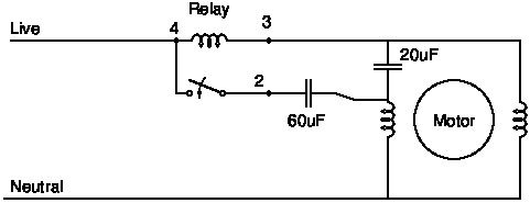
      I think you will find that the circle on the left with the 'headphones' is a klixon overload operated by heat from the motor or from high current passing through the coil. The connection at 9 o,clock is the live connection which goes through the o/l coil to pin 4, when powered up there will be high current drawn by the run winding trying to start the motor and as this goes through the coil between pins 4 and 3 this then operates the relay contacts and puts a live to the start windings, once the motor has started the current will drop and the contacts open taking the live off the start winding. The line crossing along the bottom will be the neutral. This type of relay is used on hermetic compressors on fridges etc where you cannot have a centrifugal switch, but are also useful if the centrifugal switch on a motor is beyond repair just operates by current rather than centrifugal force. But I could be completely wrong as it is 40+ years since I looked at anything like this.

      David

      Advert
      #359906
      Dennis Mulhair
      Participant
        @dennismulhair15799

        The resistance of the coil within the start relay terminals 1 & 3 is low at 0.3ohms and what looks like a capacitor is infact contacts between terminals 2 & 4 as there is no give away capacitance kick on any scale on the ohm meter. As the resistance of the winding between yellow & black is so low I'm inclined to attempt to dismantle it to see how its made. But to do that I am going to have to get bearing puller of sorts to remove the fan from one end.

        Dennis

        #359924
        SillyOldDuffer
        Moderator
          @sillyoldduffer

          Wonder if the two wires previously dismissed as a thermistor are in fact the start winding, while black and yellow are connected together at one end of the run winding. It does explain Dennis' resistance readings.

          Clive's description of how the relay works is convincing but I've not come up with a circuit that uses it and two start capacitors as well. Thought I had a solution but it's wrong. Back to the drawing board…

          Dave

          #359933
          david homer
          Participant
            @davidhomer12226

            To prove the theory that 2 of the wires are from a thermistor, why not put the motor in a warm place or a cold place and see if you get any change in resistance.

            David

            #359935
            SillyOldDuffer
            Moderator
              @sillyoldduffer

              This looks as if it might work (provided the 12ohm pair are a winding, not a thermistor!):

              asea.jpg

              Note there are two connections on top of the run winding that correspond to yellow and black. If my theory is right, the 15 ohm winding is start and the 12 ohm is run.

              Can a motor guru confirm this looks reasonable please.

              Dave

              #359938
              Frances IoM
              Participant
                @francesiom58905

                is the motor known to be good ? as as also the two capacitors? – usually on the small single phase motors I’ve seen (not that many tho) a black wire is the common of the run + start whilst both run + start are the same colour (typ white) the direction of the motor depends on which of the two legs gets the capacitance (ie motor runs as a 2 phase motor with the capacitor giving a phase lag in what is also treated as the start winding)- the larger cap switched in is to give the extra boost to get things started under load – I suspect you should be able to start under no load with just the run cap and might be a simple test ?
                However if the measurements are correct there looks to be something wrong as the two motor windings should be identical with no other link between them

                #360575
                Dennis Mulhair
                Participant
                  @dennismulhair15799

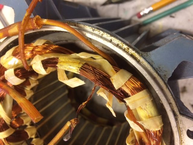
                  I opened up the motor and there are two groups of windings. Please see the enclosed photos:motor1.jpg

                  #360582
                  Dennis Mulhair
                  Participant
                    @dennismulhair15799

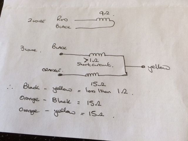
                    the connection you can see in the photo is the connection to the yellow wire from two windings. I seperated these and there was 15 ohms between one and the orange wire but a short circuit between the othere wire and the black wire, so i believe the motor is Kaput!

                    #360583
                    David George 1
                    Participant
                      @davidgeorge1

                      Were do the coloured cables go to. just interested as I am trying to get my head around the resistances in relationship to the coils etc.

                      David

                      #360585
                      Dennis Mulhair
                      Participant
                        @dennismulhair15799

                        Enclosed are my findings. There seems to be no protection device connected to black/red. Could this be the start winding?

                        mmmmm.jpg

                        #360589
                        SillyOldDuffer
                        Moderator
                          @sillyoldduffer

                          Hi Dennis,

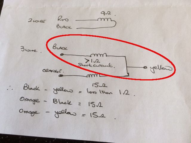
                          I think you may be right – you have a shorted winding. But that implies the motor has a tapped coil which I don't understand.

                          As David asks can you show where the Black wires go. David: this diagram is lifted from Dennis' album. I've circled the peculiar measurement. I was hoping Dennis would find Black and Yellow connected together, and they're not.

                          aseadiag.jpg

                          I feared the motor might be faulty when Dennis posted the original photo. Someone went to the trouble of disconnecting the relay and capacitors, and that could be explained by fault finding in the past.

                          My understanding of single phase motors doesn't cover split start windings, so the whole Yellow/Black/Orange thing has me stumped, if that's what they are.

                          Dave

                        Viewing 11 posts - 26 through 36 (of 36 total)
                        • Please log in to reply to this topic. Registering is free and easy using the links on the menu at the top of this page.

                        Advert

                        Latest Replies

                        Home Forums General Questions Topics

                        Viewing 25 topics - 1 through 25 (of 25 total)
                        Viewing 25 topics - 1 through 25 (of 25 total)

                        View full reply list.

                        Advert

                        Newsletter Sign-up