Sam
There are some rather clever, and distinctly expensive, bolting systems with provision for measuring the stretch when the far end is buried. The simplest way being to drill the bolt almost all the way through so an internal micrometer or special gauge can be pushed down it. Some rather fascinating offerings for really big bolts that I don't understand. I guess when you are bolting a bridge or similar structure together its advisable to get things right.
Smaller things are generally arranged with both ends of the bolt accessible so direct measurement of stretch is easy. I believe Bristol were one of the earlier exponents of this on the bolted up crankpins for the master rod on their radial engines. With up to a couple of thousand hp transmitted via one crank pin its worth taking a bit of trouble.
In general bolts and similar steel rods have two yeild points. One where the extension starts to seriously diverge from the linear expectation of Hookes law followed by a second one at a little higher stress where the material finally gives up and becomes plastic. There is usually a short, flattish, section of the stretch curve between the two sections.
Stretch bolts are made from specially formulated and heat treated material to have a relatively long extension region after the initial yield with comparatively little change in the stress needed for further stretch. The bolt is still elastic in this region so will recover if you don't stretch it far enough to go into the third part of the curve up to the final plastic yield to breaking.
It won't recover past the initial yield which is why you can't, in practice re-use them. There are theoretically arcane methods of doing so but you'd be mad to try.
The extra angular turn needed when fitting stretch bolts is to ensure that the bolt is safely in the stretch zone and able to respond to changes without running out of elasticity.
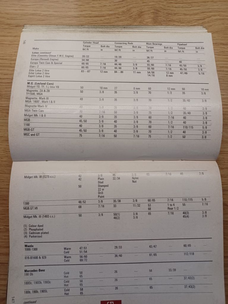
For example the old all alloy push rod V8 engine in my Range Rover has two lengths of stretch bolts to hold the cylinder head on. The manual calls out 50° turn to apply the correct stretch, near enough 10 thou / 0.25 mm. The differential expansion rates of the steel bolts and alloy engine stretch the short bolts by about 5 thou / 0.12 mm and long ones by about 9.5 thou / 0.23 mm between cold and running temperature. Objectively the Rover engine runs the stretch bolts fairly close to the limits. It doesn't take much overheating to drive the bolts out of their recovery range.
Hence the reputation for head problems after overheating when serviced by folk who shouldn't be let loose on anything beyond a Morris Minor.
The oft touted use of non stretch studs (ARP et al) has its own issue. The differential expansion pretty much doubles the clamping forces on the gasket and pushes the stud very close to their yield stress. I'm less than convinced that accepting the very wide variation in clamping force on the head gasket is a better thing than the extra care needed with stretch bolts. Pushing hot running temperature up by 10°C and forcing fast warm up to meet emission regulations was not, in engineering terms, a good thing for the motor.
Clive
Edited By Clive Foster on 26/11/2022 16:54:32
Martin Kyte.


