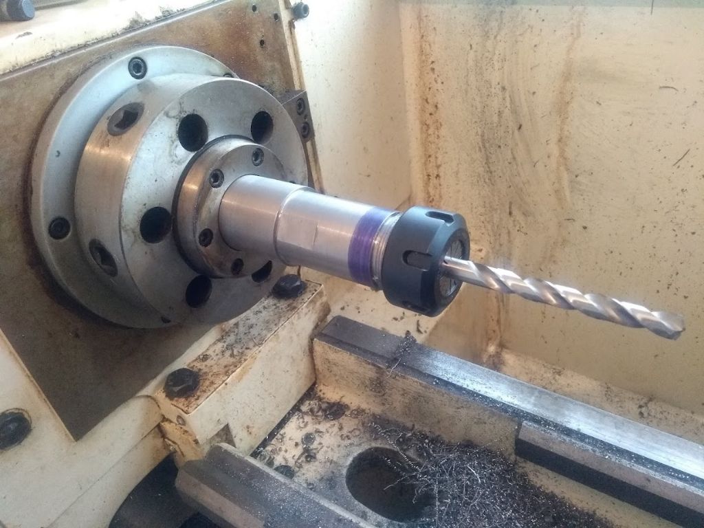
An ER32 MT5 collet holder

Advert

An ER32 MT5 collet holder

Home Forums Workshop Tools and Tooling An ER32 MT5 collet holder

Viewing 20 posts - 1 through 20 (of 20 total)
  • Author
    Posts
  • #594622
    Calum
    Participant
      @calumgalleitch87969

      I'm in the process of getting set up to do some basic milling in the lathe with a vertical slide, so one thing I need is something to hold on to those pesky cutters with. I already have an ER32 collet set, so while ER collets aren't necessarily the ideal for holding miling cutters, they seem an obvious choice. I did consider a collet chuck but I have a D1-5 spindle nose, and I don't fancy making six of those cam pins, or the price of a backplate.

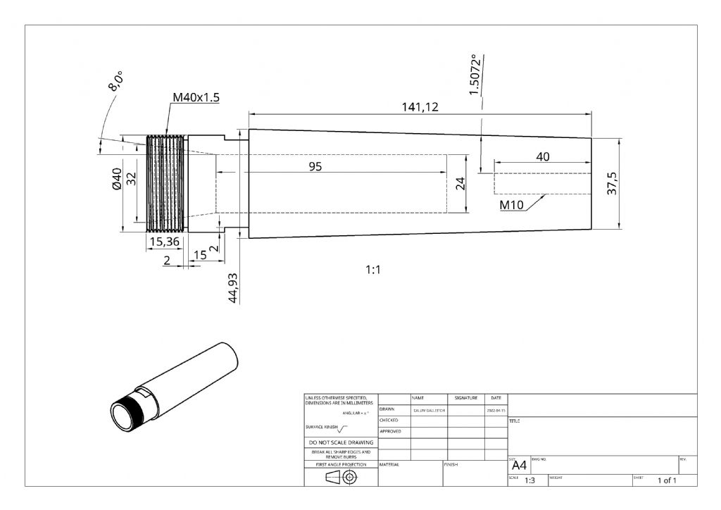
      I have about fifteen metres of M10 threaded rod lying around, as you do, so that will be pressed into service as a drawbar. Otherwise, the part essentially designs itself: an MT5 taper, with an M10 tapped hole, an ER32 nose and taper, and some flats to grip it with.

      er32coleltholder.jpeg

      Plan, such as it is:

      • Face and centre drill
      • Turn down ER end OD
      • Cut taper between centres with set-over tailstock, test fit, etc.
      • Drill out and tap drawbar hole
      • Mounted in spindle, drill and bore
      • Set up compound for 8 degree angle and cut
      • Thread run-out groove and thread.
      • File some flats
      • ???
      • Profit!

      I will also need to make a washer for the far end of the spindle bore.

      Should anyone be interested, my OnShape model is here:

      https://cad.onshape.com/documents/5744ee595b2db9b815f92457/w/5535f6d98d9b44d7634e58ac/e/84d1b32f99a61bd45596f58f

      Advert
      #20669
      Calum
      Participant
        @calumgalleitch87969
        #594627
        DC31k
        Participant
          @dc31k
          Posted by Calum Galleitch on 16/04/2022 01:17:52:

          …while ER collets aren't necessarily the ideal for holding miling cutters…

          Could you expand a little on that statement please. If they are not ideal for milling cutters, what is their designed purpose?

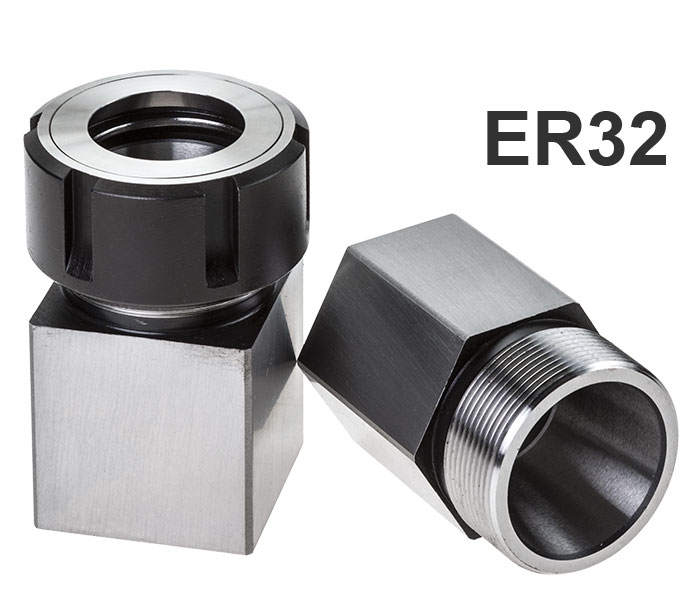
          A purchased ER32 collet block held in a four jaw chuck is an easy way to achieve what you want with very little work, and the collet block can be used on the vertical slide for workholding. It also has through-hole capacity, that a drawbar-retained tool does not.

          It might be useful for you when you are setting up to dimension the taper in terms of radius increase/reduction per unit length. How will you produce the perfectly flat-bottomed holes shown in your drawing?

          When you reverse the raw stock in the chuck to drill the centre hole at the drawbar end, there is no guarantee that the "turn down ER end OD" will remain concentric, so forming this at such an early stage is wasted work.

          You will need very straight, parallel stock to run an indicator against when setting up the offset tailstock.

          How will you check the fit of the taper? Have you a female Morse 5 socket to do that? Consider what part or parts of your between-centres you will need to disturb to check the fit (and how many times this will be necessary).

          #594630
          JasonB
          Moderator
            @jasonb

            MT5 to MT3 sleeve and your existing holder is another option either bought in or made. That way you can also hold other MT3 tooling.

            #594631
            jimmy b
            Participant
              @jimmyb

              For milling in the lathe, mounting the tooling in the spindle would, by far be the best method.

              ER collets are designed to hold all tooling.

              There are many, much more preferred methods of holding in industry, all though, I would not expect these in the home shop.

              Jim

              #594637
              AdrianR
              Participant
                @adrianr18614
                #594638
                MadMike
                Participant
                  @madmike

                  Taking AdrianR's point. Making your own tools is something we all appreciate. however I would do a quick evaluation of time, cost and need for the tool. As others have pointed out there are some potential problems with making this adaptor yourself. As Adrian has pointed out our friends at ArcEuro Trade have the MT5-MT3 adaptor you require in stock. Cost is about £13.50. I would simply buy the adaptor and get on with doing something creative with my machine. After all can you actually produce this apparently simple, but not quite so simple item at that price or anything even close to it?

                  #594641
                  jann west
                  Participant
                    @jannwest71382

                    As much fun as making your own tools is, this will almost certainly be better, quicker, and cheaper purchased (and probably hardened to boot!).

                    And, as others have said, ER is specifically designed to hold cutters.

                    #594646
                    DiogenesII
                    Participant
                      @diogenesii

                      As a 'constructional' point, it doesn't need the 24mm hole up it – the more metal in the neck of the shank the better..

                      ..the collet pockets in both of my 32 collet chucks extend only about 6-7 mm past the back end of the taper, at the back the Warco one has a raggy hole that is the lower end of the drawbar thread, the Bison one also has a through hole, but the portion at the back end of the seat is threaded 12mm L/H with a backstop screw for setting tool height..

                      #594648
                      AdrianR
                      Participant
                        @adrianr18614

                        A small change to your design could be useful. If you drill and tap the M10 all the way through you would make it easier to tap and you can then screw the studding in to act as a back stop.

                        A backstop is not much use for cutters but would be very useful if you are trying to make small parts to repeatable length.

                        #594658
                        SillyOldDuffer
                        Moderator
                          @sillyoldduffer

                          This is the sort of thing I'd rather buy than make, but don't let me put Calum off. This is an interesting challenge, with much to be learned from it.

                          As a simplification I suggest boring the drawbar's 10mm tap hole clean through, rather than leaving a bottom. Makes cutting the thread easier because swarf can escape both sides and there's no risk of the tap (or an internal screw cutter) smacking into the bottom of the hole or into a mass of compacted swarf.
                          DC31k mentions what I perceive to be the hard part of this job, which is firmly holding the part during each machining operation, and keeping it concentric throughout. For example, if the long MT taper is cut first, and the part reversed to cut the ER collar end and thread, it's tricky to grip a taper with a chuck.

                          One way of solving that problem is to machine the whole from a long rod passing through the lathe spindle held in a 4-jaw chuck so it can be accurately re-centred with a DTI each time it's slid forward. The rod inside the spindle is round and easily gripped by the chuck. First step, advance the rod enough to cut the outer collar and drill a centre hole for later, when the tail-stock is needed. Second step, slide the rod forward far enough forward to cut the taper and supporting it with a live centre in the tailstock. The thin end of the taper is near the chuck, so cut a groove just wide and deep enough for the tool and tool-post to run into without hitting anything. This leaves drilling, boring and tapping to the end. As none of these require high accuracy, the taper or collar can be supported by a fixed steady, and parting off the taper to face off and do the 10mm thread shouldn't be too difficult. (Though I'd remove the bar and saw the job off because parting-off long work becomes high-risk just before the cut finishes.)

                          Planning a complex machining job involves answering a few questions:

                          • How can I cut the shape?
                          • How can I hold the job whilst the cutting is going on, especially if maintaining accuracy is important?
                          • Can I overcome any limitations imposed by my machine's geometry?

                          All the questions have to be honestly and completely answered for each stage of production. For example, the method I describe above fails on my lathe, because it's spindle hole is only 26mm, and the bar needed to implement the method is 50mm diameter! The lathe's geometry doesn't support my method, so I need to think again.

                          Milling cutters can be held in an ordinary 3 or 4 jaw chuck. Works for light cuts, and is one of the many reasons lathe's don't make good milling machines. Replacing an ordinary chuck with an MT taper ER chuck and drawbar is an improvement, but it may not be worth the effort because the saddle and vertical vice are still compromised.

                          DC31K also mentioned Stevenson's ER Collet Blocks available square or hexagonal.

                          You could make your own round version and hold it in a 4-jaw. No need for the MT taper or a drawbar, a large diameter shank will be gripped well enough to mill on a lathe, even without flats. Less metal and much easier to make.

                          Hours of fun ahead!

                          Dave

                          #594665
                          DC31k
                          Participant
                            @dc31k

                            To be clear, I am not discouraging him from making this, but it is important to plan the work well so you do not do something at an early stage that screws you up later on, nor paint yourself into a corner by reaching a stage where you cannot easliy proceed (e.g if the the only female 5 Morse taper you have to test the piece on is the one in the spindle).

                            Posted by DiogenesII on 16/04/2022 09:29:30:

                            As a 'constructional' point, it doesn't need the 24mm hole up it – the more metal in the neck of the shank the better…

                            Have you never had to hold a cutter (or drillbit) choked up to the maximum to gain a precious 1/2" of headroom? OK, this is for milling on a lathe but the cavity behind the ER taper, of a diameter to suit the largest available collet in the range, is a good thing IMO. It's easy to add afterwards if you find you do need it.

                            —-

                            << For example, if the long MT taper is cut first, and the part reversed to cut the ER collar end and thread, it's tricky to grip a taper with a chuck. >>

                            Would you not hold the Morse taper you have just cut in the Morse taper in the spindle? That is, after all, what the permanent case will be.

                            #594673
                            John P
                            Participant
                              @johnp77052

                              Hi Calum

                              Something that you should consider before committing to 5 MT tooling,
                              you need to check the the spindle taper runs true at both the top and bottom
                              of the taper ,the sleeve that was supplied with my machine runs out
                              in the 3mt part i think that there is a slight error also within the machine taper.
                              This only matters if you were to buy a ready made piece of 5MT tooling.
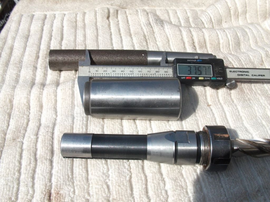
                              As you can see here from the photo the 5 mt sleeve is only 3.570" long.

                              As at some time in the future you have indicated that you will buy a milling
                              machine a useful option may be to buy a 3 MT ER collet chuck or an R8
                              and machine a sleeve to fit the lathe and then machine this in situ to suit the
                              the chuck not forgetting to engrave a mark on the spindle and sleeve and chuck
                              so they will line up in future.An ER 25 R8 chuck as seen here has a maximum
                              diameter 1.265" and the sleeve maximum diameter is 1.760".

                              Johnwarco 5mt to 3 sleeve.jpg

                              #594683
                              Calum
                              Participant
                                @calumgalleitch87969

                                > If they are not ideal for milling cutters, what is their designed purpose?

                                My understanding is that ER collets are not suitable for high torque applications, including heavy milling. Not that I intend to be doing heavy milling in the lathe anyway!

                                > A purchased ER32 collet block held in a four jaw chuck

                                Yes, I have one of these and I considered it, but I don't want to mar the external surface, as I want to be able to use it accurately in a vice, and I definitely don't want to have to dial a tool in every time I move something (my 4-jaw chuck is excessively large, a story for another day!) I was also unsure how secure a hold such a setup would really have, though it's interesting to hear that others have done.

                                > How will you produce the perfectly flat-bottomed holes shown in your drawing?

                                I will assert they are flat, and none of you will be any the wiser 😀 No, the ends of the holes will be left as is, I don't think they're particularly crucial.

                                > there is no guarantee that the "turn down ER end OD" will remain concentric, so forming this at such an early stage is wasted work.

                                It creates a space for the taper to run into, meaning that as I turn the taper down I can easily measure when I have hit the big end dimension that I want, and then use that end as a reference to face the small end to length. No, not concentric, but adequate for the operations that I'll be doing with it, I think – I don't think a drawbar has to achieve perfect concentricity. I might turn that initial OD between centres anyway just for the practice of doing so.

                                > You will need very straight, parallel stock to run an indicator against

                                Quite. It was off topic but part of this exercise will be making a between centres test bar as I've never aligned the tailstock, although it is pretty good as is for the small stuff I have done so far.

                                > How will you check the fit of the taper?

                                I'm planning to use Harold Hall's "flange" method to dial in angles both for the morse taper and the collet taper – if his claims for the accuracy of the method are true then there shouldn't be much test fitting required. But taking the piece out and removing the dead centre for a test fit isn't that onerous.

                                > MT5 to MT3 sleeve and your existing holder

                                Yes, and it would probably be sensible to have a couple of such sleeves on hand. My existing holder is MT2 which feels like a big step for these sleeves. I want to make from scratch for a few reasons though – the experience of having done it (these are all skills I want to use on trickier projects), less fiddling around hunting for things (given my ability to lose things this is not unimportant…), plus (hopefully) the accuracy of the thing being made in situ.

                                > As a 'constructional' point, it doesn't need the 24mm hole up it – the more metal in the neck of the shank the better..

                                I take the point, but there's over 8mm between the bottom of the hole and the outside taper – an MT5 taper is a beefy thing! For milling I certainly don't need all that depth, but it might well come in handy at some point for other purposes.

                                > If you drill and tap the M10 all the way through you would make it easier to tap and you can then screw the studding in to act as a back stop.

                                That's a good idea – thinking about it a drawbar probably isn't ideal as a precision backstop as it will probably move when tightened a bit but there's plenty room there to run say an M6 thread down the middle. I'd probably make it adjustable from the spindle end though as my spindle is about 400mm long so getting an allen key down there might be tricky!

                                #594696
                                Calum
                                Participant
                                  @calumgalleitch87969

                                  > This is the sort of thing I'd rather buy than make

                                  The irony is I agree with you on the principle, but for various reasons I think this one is worth tackling myself as a learning exercise (and I very much appreciate all the comments and caveats, which are a huge help). One of the things I want to make later on is a tapered reamer for chanters, which will be about 400mm long, have a taper of about 2.5 degrees, and will then need to be ground to a D section

                                  > firmly holding the part during each machining operation

                                  My thought was initial facing, centre drilling and OD turning in the three jaw, then between centres to cut the Morse taper, possibly back in the three jaw to drill the drawbar hole and face to length, and the rest of the machining in situ. I do need to check I can get my toolpost up that close to the spindle nose.

                                  > machine the whole from a long rod passing through the lathe

                                  I did think of this, the main issue being my compound only has 80mm of travel – I know with a bit of care one can overcome this sort of problem but I think it's easier not to give myself problems to start with!

                                  > you need to check the the spindle taper runs true

                                  Thanks John, a very good point – I think I measured the parallel section of the bore as being very close to 38mm but I will check it again. I have an MT5 dead centre on the way so that will be a useful check as well.

                                  #594714
                                  AdrianR
                                  Participant
                                    @adrianr18614

                                    Callum,

                                    A backstop does not need to be accurately set, it just has to be accurately repeatable. Once the collet holder is in the spindle, backstop set and tightened down, it won't move.

                                    To get an accurate length, face off the pice slightly longer than needed, then remove and measure the length. Now you know how much more to move the tool to get the length you need. Now every piece can be made to that length.

                                    Adrian

                                    #598884
                                    Calum
                                    Participant
                                      @calumgalleitch87969

                                      Well, finally a quick progress report – no pictures so far, I'm afraid, I forgot to bring the phone to the workshop two days running. I've been following the process I outlined in my original post and have the taper cut and the drawbar thread drilled and tapped. I've also made the drawbar washer and chopped off a piece of studding to length.

                                      It's been a very educational experience so far. One of the preliminary projects I had to do before this one was make a driving pin for a lathe dog; I decided to make a pin with a camlock stud on one end. I have two quick tips here: one, you have to put a shoulder where the ISO drawings show a setting line, and secondly, interestingly the length of a D1-5 stud to the setting line is the same as the overall length of a D1-4 stud, so I managed to read the wrong set of measurements and now possess the world's only double-ended camlock driving pin. The good news was that the circular cutout on the stud is about the same radius as my semi-circular bastard file.

                                      On the collet holder itself, I used two indicators to establish the offset angle, but it hadn't occurred to me that it only works if your stock is parallel to start with, and it wasn't until several iterations of altering the tailstock had occurred that I worked this out – so back to getting it on centre, an adventure in itself. It took quite some time to dial in the angle I wanted, and one thing I should have worked out before I started was the necessary tolerance.

                                      Using the change in the indicator readings, I was working out the tangent of the angle defined by the tailstock offset, aiming for tan(1.5072), which is about 0.026312. I found trying to get that fourth decimal place was a frustrating exercise; it's at the point where merely taking the slack off one set screw and retightening the other moved it further than you want. Having got to about 0.0264, I decided that I wasn't going to get closer and went ahead and cut it.

                                      The actual cutting was straightforward and having cut the stock over length in case of error, when I got the small end to dimension I tried a test fit and…a solid fit. I had to knock it out again. Being a simple creature, I stopped there, on the premise you should quit while you're ahead.

                                      The next day involved the making of a test bar to get the tailstock back on centre, which I hadn't previously done. It turned into a faff, as it was too small for the driving dog, so I made a little cutout piece on the bandsaw to clamp it properly, during which the bandsaw threw the blade off, then I couldn't get the cover back on…some hours later though I had two flanges, one reading 24.71mm and one reading 24.72mm which as we all know is the same thing.

                                      The drawbar hole has now been drilled and tapped, just held in the three jaw, and the part is now sitting in the spindle held by the drawbar. I've turned the straight section to a hair under 40mm ready for external threading, and drilled the first pilot hole for the internal hole.

                                      The part is quite a bit longer than it needs to be at the moment; I think I'm quite happy leaving it as is as it gives me scope to screw up and will work fine if I get it right first time.

                                      #598985
                                      Howard Lewis
                                      Participant
                                        @howardlewis46836

                                        Good work Callum.

                                        Have you ever heard the song "There's a hole in my bucket, Dear Liza"?

                                        As always, every apparently simple job spawns three others!

                                        Howard

                                        #598992
                                        Calum
                                        Participant
                                          @calumgalleitch87969

                                          Good heavens, Howard, that brings back memories. Somewhere I have a very, very old LP with Pete Seeger's rendition of it.

                                          #599722
                                          Calum
                                          Participant
                                            @calumgalleitch87969

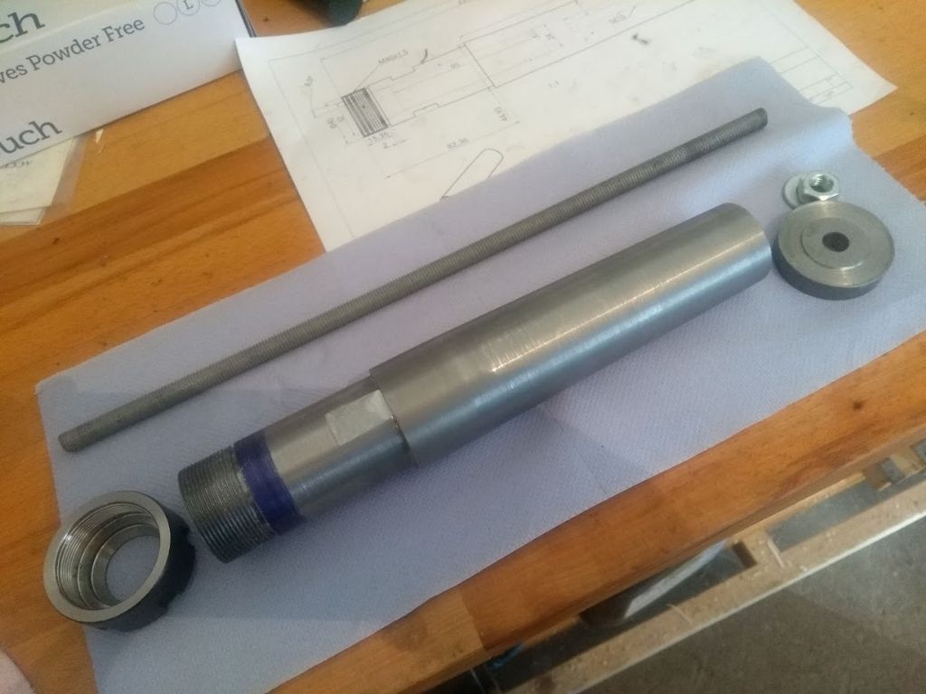
                                            img_20220528_180405216.jpg

                                            A finished collet holder, along with drawbar and washer. As can be seen from the (posed) action shot below, it's ended up a good bit longer than necessary:

                                            img_20220528_181003282.jpg

                                            I cannot lie, the temptation to chop the nose off and make it a bit shorter is tempting. However, it works, and while it looks a bit daft I can't see it causing a practical problem, and I'm not short of room on the bed of the lathe. Plus, if I use it to hold stock I have lots of depth, and there's actually lots of meat to drill it even deeper if I wanted to.

                                            A couple of things do bother me: the finish is terrible. I'm using cheap carbide inserts and these are probably part of the problem, but I think the biggest problem was the the dog and driving pin contained enough mass to cause a good bit of vibration while turning the morse taper. I tried several iterations of speed and feed and depth of cut and was never really happy with anything by the time I hit dimension.

                                            The other thing is that the threads are really poor in appearance. I was having a senior moment and started cutting the threads by plunging into the work with the cross-slide, rather than setting the compound at an angle and using that to advance the cut. Whether that was the cause or something else, I am not sure but the threads look awful – lots of tearing/scaliness. Would a thread file clean it up a bit? There is a bit of wiggle room, as I stopped as soon as the nut threaded on, so a little more could come off safely.

                                            One issue I had was that it turns out my toolpost doesn't have enough vertical height to put boring bars on centre. I ended up bolting the 16mm dia boring bar to a piece of 8x20mm flat stock and clamping that in the toolpost with lots of shim; I think well-boiled spaghetti might have been more rigid. It took a bit of fiddling to learn to take an effective cut with it – too small, chatter, too big, it shifted under the load.

                                            All in all, I learnt a lot from this that will be useful in future, so I'm glad I went ahead with it. I'm finding myself getting a lot more comfortable working with the lathe and knowing what to do to get good results.

                                            The next project is to setup my comically oversized milling vice ('hmm, 4" doesn't sound like much, that's do fine', I said to myself) to the vertical slide, and once I have that secure and square I can bash on with the QCTP build, and then maybe I can make things 😀

                                          Viewing 20 posts - 1 through 20 (of 20 total)
                                          • Please log in to reply to this topic. Registering is free and easy using the links on the menu at the top of this page.

                                          Advert

                                          Latest Replies

                                          Viewing 25 topics - 1 through 25 (of 25 total)
                                          Viewing 25 topics - 1 through 25 (of 25 total)

                                          View full reply list.

                                          Advert

                                          Newsletter Sign-up