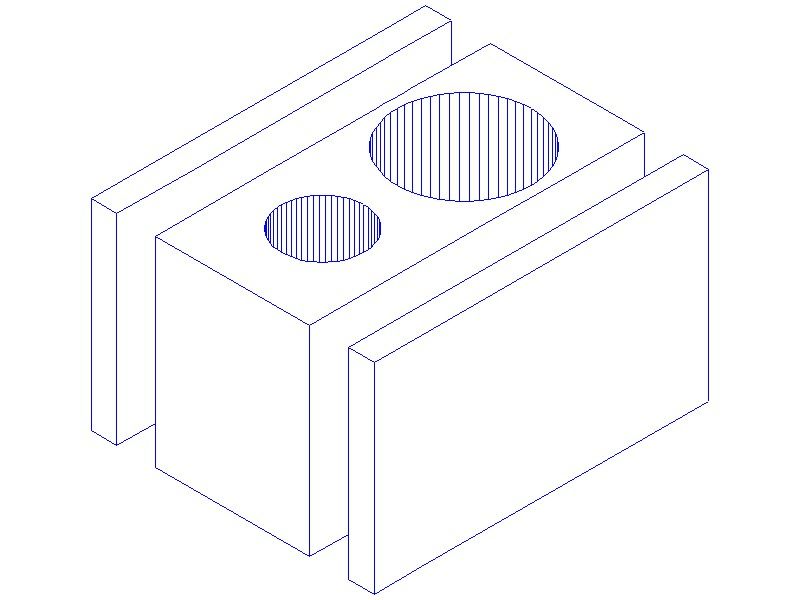
This is a sketch of Option 1, exploded. It is to scale using the candidate block of iron; but I have omitted all details including the ports – which would have been very difficult to draw.
The ports are dug out of the end faces so there is not very much depth left for the LP passages. The 52mm (2" ) LP cylinder wall is only 15mm from the port face at its closest, and on the arrangement above only about 3mm from the sides of the casting. The screwed-on plates are drawn at 10mm thick, the block nominally 60 mm wide, to hold an LP cylinder cover 75mm / 3" diameter.
The ports, the overall length over port-faces, and the valve-spindle and cylinder centres, are all set. I can't change them.
.
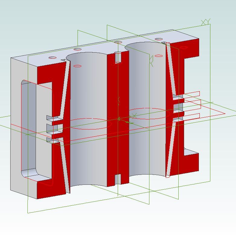
The existing block is much wider, but I drilled the passages parallel to the port faces, so quite shallow-lying, and when I drilled the valve-chest studs years (literally) later, some go straight into them.
The passages meet the bores by milled recesses that leave very narrow lands for sealing at the ends of the block, though the gasket would receive some support from the valve-chests – if I had thought to make the chests slightly over-long.
This arrangement was easy to machine but creates disproportionately large clearance volumes. One of Luker's locomotive drawings in ME showed me what I should have done!
I've also now problems trying to find room for the HP steam inlet, and the connecting and starting-valve pipes or passages. The ancient photograph that is my GA "drawing" shows the steam pipe meets the back face of the HP valve-chest via a fitting with a long vertical lever, which I take to be the starting-valve. The regulator is merely a globe-valve on the top of the boiler!
.
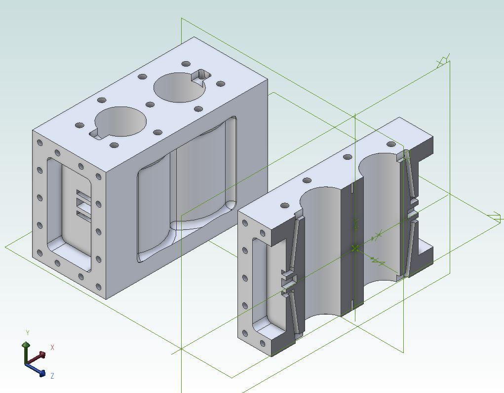
The attached drawing, in TurboCAD, is on my 3D CAD limit. I aligned 3 rectangles and 2 circles along the Y-axis, spaced then extruded them with the circles over height and depth, so subtracting the "solid" cylinders from the block left the two holes.
The facets are a result of how TC extrudes circles. It imprints a polygon on the base circle then extrudes that to form a prism it calls a "TC surface", but you can edit the appearance by raising the facet count – I chose 60 here. These are horrors – some basic editing tools break the prism into separate facets you cannot reunite; and I have never discovered what if any pattern there is to it.
I don't have drawings for the original block. To investigate milling out the original passages and fitting inserts to give properly-inclined passages, I found drawing it in 3D CAD far too difficult. If I ever had a paper drawing of it, drawn some 20 years ago, it would be on a sheet too large to scan.
Nigel Graham 2.


