I'd like to install a 3-phase motor (0.37 or 0.25 kW would fit) into my Hobbymat MD65, and control it with a VFD. I've been reading on the topic of VFDs, and looks like the most proper way to install one is to hardwire it to the mains, as well as to the motor.
But in my case, that is not very practical. My little lathe normally sleeps on a shelf, when I want to use it, I take it out and bring it to the workbench. Ideally, I would like a portable VFD unit that would normally stay on another shelf (the lathe takes a whole shelf), and can be brought out and connected to the lathe, when needed. It would be also possible to have the VFD permanently mounted on the wall, but still it would need some way to quickly connect it's output to the lathe when I bring it to the workbench.
I'm contemplating a metal enclosure (perhaps an old PC case?), with an IEC socket for connecting the mains power. Inside would be an EMC filter, the VFD, and possibly a braking resistor (maybe overkill for such a little lathe). Both the lathe and the VFD enclosure should have some sort of 4-pin sockets that could be connected together with a suitable pigtail. Another option would be to pass a cable from the VFD out from the enclosure (through a gland), with a 4-pin plug on it's end, to connect to the lathe.
For forward/stop/reverse/E-stop/speed control on the lathe, I'm thinking about adding RJ-45 connectors on both the VFD enclosure and the lathe, connected via a shielded patch cord.
I have a couple of concerns:
Safety. Most VFD manuals mention that the motor should never be disconnected from the drive during operation (this could destroy the VFD). With 1 or 2 plugs/sockets which could be disconnected, this could be an issue. So the connectors must be lockable, to prevent accidental disconnecting. It might also be a problem if, when setting things up, the VFD is plugged in first and turned on while forgetting to connect the motor. This can be fixed either by proper discipline, or adding an extra pin to the motor connector, which would be a part of safety interlock circuit (until it's connected, the VFD can't be turned on).
EMC/RFI: Reading the VFD manuals and information available on the net (mostly geared towards professional industry), it appears that there are many requirements in wiring up a VFD to avoid excessive interference (I'm in residential environment – my "workshop" is in a cellar inside an apartment building). The connection between the VFD and the motor seems to be an important aspect of that wiring, using a shielded cable, correctly grounding that shield on both VFD and motor sides. I couldn't find any info on properly wiring an arrangement like I'm imagining. I wonder how the plugs/sockets on the motor power wire will affect EMC.
I would like to hear opinions, whether or not this plan makes sense or should be forgotten. If it makes a bit of sense, I hope someone can offer suggestions on implementing this project, for example which connectors would be good to use for the power wire, how to deal with the wire's shield, and any other advice 
Thanks!
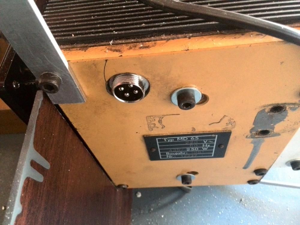
P.S. Here's a picture from a Russian-language machinists forum, this user installed a "VEM 0,4 kW 1500 RPM, frame size 71" motor and a VFD, and used some kind of screw-on 4-pin socket to connect power to the lathe.

 Robert Atkinson 2.


