Myford ML2 Change gear headache help needed.

Advert

Myford ML2 Change gear headache help needed.

Home Forums General Questions Myford ML2 Change gear headache help needed.

Viewing 25 posts - 1 through 25 (of 33 total)
  • Author
    Posts
  • #240041
    Richard Hardcastle
    Participant
      @richardhardcastle

      Hi.

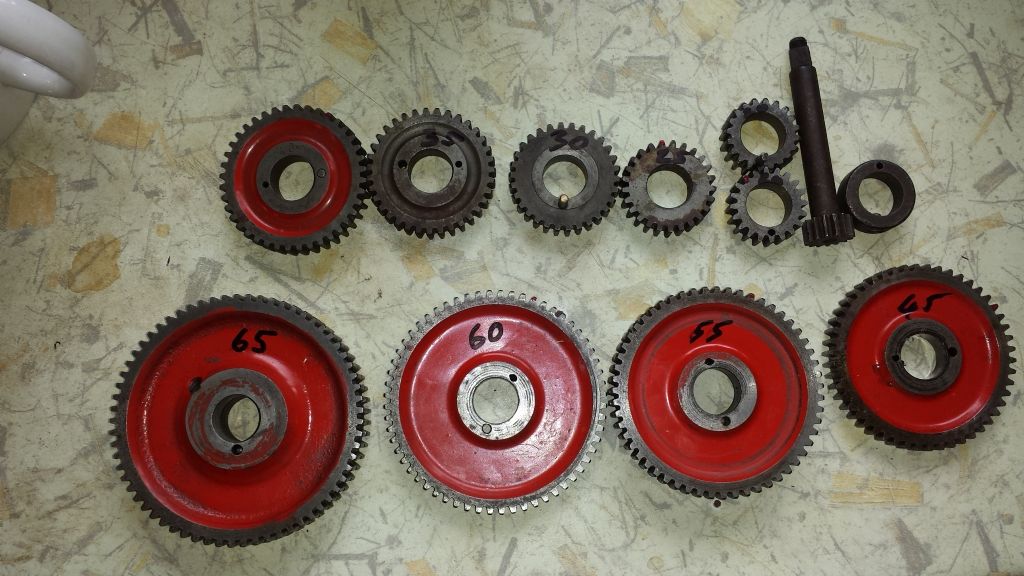
      I'm wanting to start practicing cutting threads on my ML. I have most of the change gears, 1 x 15t on a shaft???, 2 x 20t, 1 x 25t, 1 x 30t, 1 x 35t, 1 x 40t, 1 x 45t, 0 x 50t, 2 x 55t, 1 x 60t, 5 x 65t and one collar. I'm certain I have a 50t as well but I can;t find it and it's one of the gears I need for a 20UNF thread

      Anyway the little chart in my garage says I need a 20t on the mandrel and 50t on the leadscrew and idlers on the 1st (upper?) and 2nd (lower?) studs. When I take the gears of the leadscrew and try and fit a 50t (must have been a 55t) the lower idler can't reach it as it's a compound gear and the larger of the 2 gears prevents the smaller one engaging with the 50t on the leadscrew.

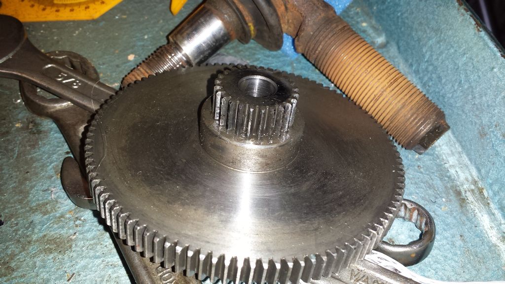
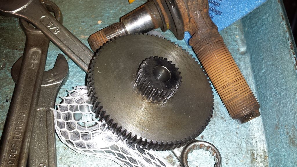
      So I'm wondering just what the idler gears should be. I recently bought the lathe of a chap who didn't really seem to know much about lathes so couldn't give much . On the upper rearmost stud (1st stud?) there's a single peace compound gear with MOD1-100 written on it.

      mod1-100_1st-stud-a.jpg

      On the lower stud(2nd stud?) is another compound gear with MOD1-80 written on it.

      mod1-80_2nd-stud-b.jpg

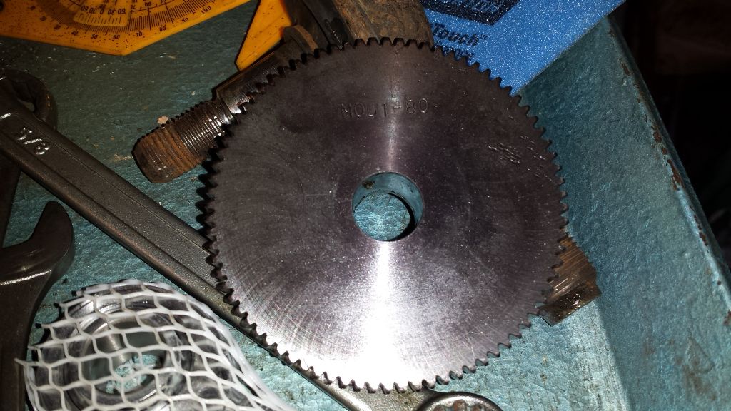
      And on the leadscrew is a single gear with MOD1-80 written on it.

      mod1-80_screwthread-b.jpg

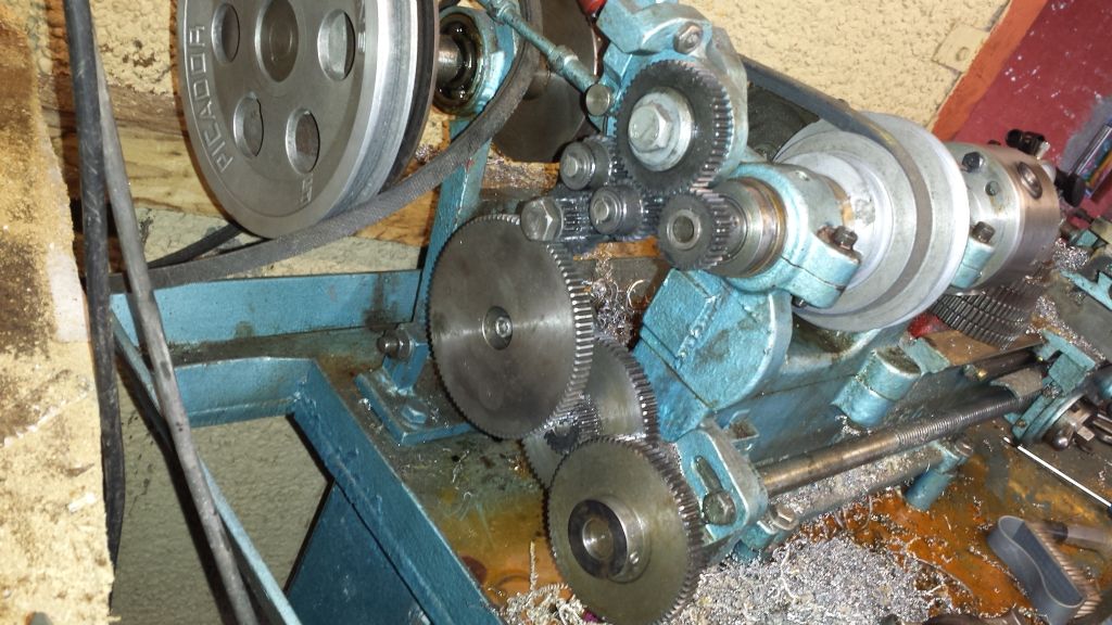
      This is how they are arranged,

      changegears.jpg

      Also the diameter of te 1st and 2nd studs are much smaller than the holes in my change gears is there supposed to be some sort of bush I should have?

      Here are my change gears.

      20160524_132059.jpg

      If somebody could help me understand what gears I need and where/how to fit them I would be very grateful as I have been brought to an abrupt stop with my little project

      Many thanks

      Rich

      Advert
      #24558
      Richard Hardcastle
      Participant
        @richardhardcastle
        #240047
        Martin Kyte
        Participant
          @martinkyte99762

          Um guessing a little here as I have never used a ML2 but you don't need two idlers if you have a tumbler reverse and you almost definitely need a sleeve. Looks like the ML2 used pins to lock the gears together as pairs the same way Drummond did. Later Myford used keyed gears.

          regards Martin

          #240048
          Howard Lewis
          Participant
            @howardlewis46836

            Its a long time since I sold my ML7, but do not think that Myford used Mod 1 gears, but 20DP; so your lathe may have been hybridised (or a previous owner did know what he was seeing, and labelled them wrongly).

            The ML2 and 4 used pins to connect gears, and gears were prone to breakage because of the small wall sections, if abused.

            (Once made a couple of 20DP replacements for a friend with a ML4, who had just that problem)

            Would be worth checking what the gears that you have, really are.   If 20DP, a 20T gear will measure 1.1" OD Formula is OD = (T+2 ) / DP, if you want to check some of the other gears.

            H T H

            Howard

            Edited By Howard Lewis on 24/05/2016 15:18:22

            #240064
            John Fielding
            Participant
              @johnfielding34086

              Hi Richard,

              That ML2 looks awfully like my Grayson lathe! In fact Myford bought Grayson and copied it.

              The idlers are exactly what they say they are, they simply allow you to span the two wanted gears to get from the mandrel to the leadscrew. So any two suitable gears will do that fit OK. Assume the mandrel has a 20T gear and the leadscrew has a 60T gear. If you could couple them directly then the reduction would be 1:3.

              Now interpose any idler gear, let us say it is 40T. Then the idler gear will rotate 1 turn for every two turns of the mandrel gear. Now couple that 40T to the 60T leadscrew gear and it will rotate the leadscrew 40/60 per rev, that is a reduction of 1:1.5. Multiply 1.5 x 2 for the two ratios and you 3:1, which is what you would get without the idler gear in place.

              So the idler does not effect the overall ratio and hence any suitable gear will work. Cascade as many idler gears as you like and the overall ratio is simply the first and last gear – as long as you have each idler on a separate spindle. However, if you couple two gears on a common spindle with the drive pins then it becomes a "compound gear" and the number of teeth do have an effect.

              I hope that helps?

              #240088
              Richard Hardcastle
              Participant
                @richardhardcastle
                Posted by Martin Kyte on 24/05/2016 15:11:20:

                Um guessing a little here as I have never used a ML2 but you don't need two idlers if you have a tumbler reverse and you almost definitely need a sleeve. Looks like the ML2 used pins to lock the gears together as pairs the same way Drummond did. Later Myford used keyed gears.

                regards Martin

                Yep the gears are drilled for pins…2 different diameters for some reason. I think the mandrel gear is currently a 25t or a 30T but I'm not sure in the tumbler reverse will still engage properly, I'll have to check that. When you say "almost definitely need a sleeve" do you mean for the 1st and 2nd stud so they will accept the changegears?

                #240090
                Richard Hardcastle
                Participant
                  @richardhardcastle
                  Posted by Howard Lewis on 24/05/2016 15:14:19:

                  Its a long time since I sold my ML7, but do not think that Myford used Mod 1 gears, but 20DP; so your lathe may have been hybridised (or a previous owner did know what he was seeing, and labelled them wrongly).

                  The ML2 and 4 used pins to connect gears, and gears were prone to breakage because of the small wall sections, if abused.

                  (Once made a couple of 20DP replacements for a friend with a ML4, who had just that problem)

                  Would be worth checking what the gears that you have, really are. If 20DP, a 20T gear will measure 1.1" OD Formula is OD = (T+2 ) / DP, if you want to check some of the other gears.

                  H T H

                  Howard

                  Edited By Howard Lewis on 24/05/2016 15:18:22

                  The original owner of the lathe was an engineer and it was his personal lathe that he had at home so he could have altered things I guess. Apparently he used it for making model jet engines. I've checked a few of the gears and they seem to be 20DP….what does 20DP actually stand for lol???

                  #240093
                  Bazyle
                  Participant
                    @bazyle

                    The 'MOD' gears you have are NOT the same a the rest of the gears. The holes and pins for locking them together should be a clue. They should clearly have different teeth sizes and don't try to run them together.

                    ML 2 is NOT the same as ML7. The early Myfords used the same 14DP gears a the Drummond. Only for later models were the smaller 20 DP gears introduced.

                    DP is Diametric Pitch (which google seems to want to call Diametral Pitch). It is a standard measuring system for gears used in imperial units. Mod is short for Modular which is the standard for metric gears. Look them up.

                    #240095
                    Brian Wood
                    Participant
                      @brianwood45127

                      Hello Richard,

                      Myford used 20 DP cast iron gears, with steel as the material in 20T and 25T gears, being a lot stronger. As others have said, they are linked by pins in the lower part of the gear. The gear bore was always 5/8 inches [0.625]

                      Ideally you need two working gears in the chain, a 20T as the mandrel gear [the one sharing the reversing gear cluster] through two idlers [size immaterial] to a 50T wheel on the leadscrew. That will give you the right gearing for a 20 tpi pitch thread. It would pay you to get a 50T wheel from Myford, or find the one you the missing one, you will need it frequently and make your own pin drilling in the wheel boss. It will come with a keyway, but that won't matter.

                      Certainly, Myford did not use module gears, the pressure angles don't match and the nearest size to 20 DP is 1.25 mod. Even that would won't mesh well so your 1 mod wheels won't mesh at all with the Myford wheels you do have. I would sell those on ebay, they are effectively useless for this lathe.

                      Regards

                      Brian


                      Edited By Brian Wood on 24/05/2016 18:39:33

                      #240096
                      Richard Hardcastle
                      Participant
                        @richardhardcastle
                        Posted by John Fielding on 24/05/2016 16:29:39:

                        Hi Richard,


                        That ML2 looks awfully like my Grayson lathe! In fact Myford bought Grayson and copied it.

                        The idlers are exactly what they say they are, they simply allow you to span the two wanted gears to get from the mandrel to the leadscrew. So any two suitable gears will do that fit OK. Assume the mandrel has a 20T gear and the leadscrew has a 60T gear. If you could couple them directly then the reduction would be 1:3.

                        Now interpose any idler gear, let us say it is 40T. Then the idler gear will rotate 1 turn for every two turns of the mandrel gear. Now couple that 40T to the 60T leadscrew gear and it will rotate the leadscrew 40/60 per rev, that is a reduction of 1:1.5. Multiply 1.5 x 2 for the two ratios and you 3:1, which is what you would get without the idler gear in place.

                        So the idler does not effect the overall ratio and hence any suitable gear will work. Cascade as many idler gears as you like and the overall ratio is simply the first and last gear – as long as you have each idler on a separate spindle. However, if you couple two gears on a common spindle with the drive pins then it becomes a "compound gear" and the number of teeth do have an effect.

                        I hope that helps?


                        Yep I can see how that will work for single gears per spindle as they are just passing the drive onto the next gear a tooth at a time. So to have the lead screw turning in the correct direction I'll need to use 2 idlers…unless I can still use the tumbler reverse after changing the mandrel gear?


                        So if I have a 20t on the mandrel, a 50t on the lead screw and the lead screw is 1/8" per revolution and I want to cut a 20tpi thread the sum is 20(turns of mandrel) x 20(teeth) / 50(teeth) / 8(turns of lead screw) = 1(inch travelled along work peace)? Or is that all wrong lol?

                        Edited By Richard Hardcastle on 24/05/2016 18:42:41

                        #240097
                        Bazyle
                        Participant
                          @bazyle

                          If you read the last 6 months of threads on the forum you will find a few previous topics about thread cutting gear selection. You should find in that some computer programmes that help you calculate alternative gear combinations that do not need the missing gear.

                          #240107
                          Richard Hardcastle
                          Participant
                            @richardhardcastle

                            Thanks for all the info I'll have a look through the forum an see what I can dig up. I have nthreadp which is stating;

                            Driven gears 25 40 Driver gears 20 20 TPI 20 error % 0
                            Driven gears 25 60 Driver gears 20 30 TPI 20 error % 0

                            So I think that's a 20t on the mandrel driving a 25t on a compound locked to a 20t which drives a 40t on the leadscrew.

                            #240164
                            Brian Wood
                            Participant
                              @brianwood45127

                              Hello Richard,

                              That assumption is correct.

                              The reduction you need between mandrel and leadscrew is 0.4, so whatever combination you build up should achieve that to give you the pitch you need. The sums are simple; drivers multi[plied together divided by driven wheels multiplied together.

                              The product of that should be 0.4 and then multiply by 0.125, [the pitch of the leadscrew]. For 20 tpi, the pitch will be 0.05, the inverse of which is 20

                              Regards

                              Brian

                              #240169
                              John Fielding
                              Participant
                                @johnfielding34086

                                Hi Richard,

                                A very good book to tell you all you want to know is by Ivan Law, which Tee Publishing advertises. IIRC it is Gears and Gear Cutting, or something like that.

                                As others have mentioned the Myford/Grayson series of the smaller lathes used 20DP with a 14 1/2 degree pressure angle. The angle isn't important for now but the DP bit is. Basically the DP is the number of teeth for each inch on the periphery of the gear. So a 20DP gear of 20T is about 1-inch in diameter, a 40T gear is about 2-inch etc. The reason I say "about" is because the pitch circle diameter is measured part way up the tooth profile and not at the top. By measuring the number of teeth and the OD you get a pretty good idea what the DP number is, it is usually a whole number but there can be exceptions to that rule!

                                Any 20DP gear will mesh correctly with any other irrespective of diameter or number of teeth, you only need to adjust the center distance to have a good transmission via the gears.

                                The direction the lead screw rotates can be changed by the tumbler reverse gears and it depends on the number of idlers in the chain. With one idler the mandrel and lead screw will both turn in the same direction. With two idlers the lead screw is reversed, hence why the tumbler reverse gears are fitted.

                                On my Grayson 3 /13-inch lathe, the fore-runner of the ML7 it seems, the change gears have two types of studs and some have a spacer sleeve to change diameter as well. The nominal center hole is 5/8-inch and they have either one or two pin-holes for the driving pins. When Myford brought out the ML7 they added key ways and left out the pin-holes, but otherwise the gears are the same.

                                #240178
                                Martin Kyte
                                Participant
                                  @martinkyte99762

                                  You may find this previous thread handy too.

                                  **LINK**

                                  Martin

                                  #240197
                                  Richard Hardcastle
                                  Participant
                                    @richardhardcastle

                                    OK I’m a little concerned now add more than one person has said that the MOD1 gears won’t mesh with the standard gears for my lathe. However they were fitted when I collected the lathe and I’ve been using it like that ever since. Does that mean the tumbler reverse gears are also MOD1 type and will also need removing?

                                    #240205
                                    Martin Kyte
                                    Participant
                                      @martinkyte99762

                                      Sounds like you do need to go through and find out exactly what each gear you have is.

                                      Any Module 1 gears will mesh with any other module 1 gear and any 20DP will mesh with any other 20DP.

                                      The operative word is mesh. I assume that your first gear is just going on the tumbler gear shaft and doesn't mesh with the tumbler gears. In that case it does not matter what is in the change wheel train so long as they are all the same pitch.

                                      Think screw threads if you like. you cannot put a 1/4" BSF bolt into a 1/4" BSW nut. The BSF is 26 Threads Per Inch and the BSW is 20 per TPI so they dont mesh and lock up part way in. Gears are exactly the same. The previous owner of the lathe may well have machined up some gears with tooth numbers he didn't have for a job and only had a Module 1 cutter to hand. So long as you mesh same with same that is fine just a little confusing when you receive a box of bits with a lathe you have just bought.

                                      Module 1 is 25.4 DP so will not mesh with 20DP or if they do they will not mesh correctly.

                                      regards Martin

                                      #240213
                                      Hopper
                                      Participant
                                        @hopper

                                        Don't ger rid of your Mod 1 gears! They look very useful. It is entirely possible, and indeed was not unusual practice in the days before the cornucopia of cheap internet tools were upon us, to use gears of two or more modules or DPs to construct a gear train.

                                        It looks like the Mod1 gears you have are set up to provide a nice fine feed for turning, finer than the standard Myfrod gears would provide. It looks like the Mod1 compound gears with the 100T and 80 tooth and 20tooth gears coupled together mesh with a Mod1 gear that has been attached outboard of the original 20DP output gear on the reversing quadrant.


                                        So keep your big and little MOD1 gears and use them meshed as shown in your pic for nice fine turning feed.


                                        For screwcutting, use the original 20dp gears but set up to mesh with the inboard gear on the reversing mechanism's output shaft. Plenty of Myford 20dp change wheels come up on Ebay UK every week. So you should be able to buy one for a few pounds. Or keep using the compound gearing app you have already discovered.

                                        And if you get Martin Cleeve's excellent little book "Screw Cutting in the Lathe" (workshop Practice series, Tee publishing) he has a chart in there of how to cut metric threads using your standard change gears on an 8tpi leadscrew lathe. No need for fancy 127T gears or the likes. Just the magic of compound gearing.

                                        YOu may even be able to use your MOD1 gears for screwcutting in combination with the 20dp by using compound gearing. You have to be able to put a MOD1 gear and a 20dp gear on one stud as a compound combination, then the rest of the train is made up of MOD1 gears that mate up with one of the compound gears, then the rest of the train is made up of DP gears that mate with the other gear on the compound pair.

                                        Edited By Hopper on 25/05/2016 13:09:15

                                        #240224
                                        Richard Hardcastle
                                        Participant
                                          @richardhardcastle

                                          Thanks to everybody for your help so far. I'll see if I can get hold of the books you mention as there is so much for me to learn and I really do have to get my head around gear ratios especially compound gear ratios so that I can "feel" if the ratios suggested by software seem right.

                                          Martin I've book marked the discussion your link points to as it is quite helpful.

                                          Hopper I will keep the Mod1 gears as the feed rate they produce is very slow which is ideal for me as it keeps things happening slowly and also takes some of the strain off the lathe if I try to take too big a cut. If I'm right you are saying that all the gears from the mandrel to the inner gear of the compound on the reverse tumbler will be 20dp and then the outer gear is Mod1 to mesh with the rest of the gear train which is also Mod1?

                                          If that is so then to set up a 20t-50t (my new 50t arrived this morning) to cut a 20tpi thread I'd swap the outer Mod1 gear of the reverse tumbler compound for a 20t 20dp gear and fit the 50t 20dp to the lead screw and fit suitable 20dp idlers between them?

                                          I also like your comment about being able to mix and match the 20dp and Mod1 gears provided I always have them meshed like for like, so the switch would take place on a compound gear. For instance no harm would be done by leaving the Mod1 outer gear on the reverse tumbler output compound which could drive a Mod1 compound which in turn could mesh with a Mod1 gear locked to a 20dp gear to form the 2nd compound which in turn could mesh to a 20dp on the lead screw…I think lol.

                                          I will put the gears back in their original positions and make some bushes so I can fit the 20dp gears onto the studs for the Mod1 gears…it'll give me a little practice

                                          #240225
                                          John Fielding
                                          Participant
                                            @johnfielding34086

                                            You got me thinking about the Grayson gears and as I don't use this old lathe any more all the bits are stored away.

                                            Out of curiosity I dug out the change gears and the quadrant etc to take a closer look. I was surprised when I cleaned off all the dirt that the big gear which normally fitted on the lead screw is a bit odd. I had measured it some years ago before storing everything away. It has what looks like a makers name cast into the side, seems to be PK and the other side has the number 112, presumably the number of teeth. But on looking more closely it actually has 90T and they are not 20DP. After faffing around a bit they seem to be either 16DP or 17DP depending where on the teeth you assume the pitch circle is. My assumption is it is a 16DP as odd number were considered an "oddity". I wonder if the previous owner used a 112T and machined the teeth off to cut new ones? There isn't a lot of metal left on the rim and that suggests that is what they did. The gear does have a key way but someone had fitted a sleeve to adapt to the 5/8-inch lead screw stub shaft.

                                            The other smaller gears are definitely 20DP, same as the Super 7 ones and they are interchangeable. I have a fixed compound gear set that goes between the quadrant gears and the large 112/90T lead screw gear. Never noticed they were different! The age of the lathe predates Mod gears I think?

                                            The tumbler reverse gears are also not 20DP, which I never noticed before. So it seems that Grayson may have used two different types and Myford simply copied the design when they bought Grayson all those years ago. The plot thickens!

                                            #240234
                                            Hopper
                                            Participant
                                              @hopper
                                              Posted by Richard Hardcastle on 25/05/2016 13:47:41:

                                              Hopper … If I'm right you are saying that all the gears from the mandrel to the inner gear of the compound on the reverse tumbler will be 20dp and then the outer gear is Mod1 to mesh with the rest of the gear train which is also Mod1?

                                              Yes, that is what I am saying.


                                              If that is so then to set up a 20t-50t (my new 50t arrived this morning) to cut a 20tpi thread I'd swap the outer Mod1 gear of the reverse tumbler compound for a 20t 20dp gear and fit the 50t 20dp to the lead screw and fit suitable 20dp idlers between them?

                                              Yes and no. To get a 20/50 overall ratio, you would need a 20 on the actual lathe headstock spindle, aka mandrel, and a 50 on the leadscrew. You can then run any string of idlers in between the two gears and the ratio is still 20/50. But if you run two gears on one stud, such as that reversing tumbler output shaft, ie compound combination, the two gears must be the same number of teeth each in order to give a 1:1 compound ratio. It might be possible rather to use the inner gear on that output stud, assuming it is a 20dp and mesh the next idler gear with that gear.

                                              I also like your comment about being able to mix and match the 20dp and Mod1 gears provided I always have them meshed like for like, so the switch would take place on a compound gear. For instance no harm would be done by leaving the Mod1 outer gear on the reverse tumbler output compound which could drive a Mod1 compound which in turn could mesh with a Mod1 gear locked to a 20dp gear to form the 2nd compound which in turn could mesh to a 20dp on the lead screw…I think lol.

                                              Yep, you got it. I think it was Prof Chaddock of Quorn fame who suggested in one of his books or articles that the model engineer should collect any gears they could scrounge up and use them in such a way to build compound gear trains of varying DP's where needed. It was probably just easier and cheaper for your old engineer previous owner to buy off the shelf (or "borrow" out of the store at work) MOD1 gears than to try to source 100tooth 20dp gears etc.

                                              I will put the gears back in their original positions and make some bushes so I can fit the 20dp gears onto the studs for the Mod1 gears…it'll give me a little practice

                                              Also, can you post a few more pics of that reversing tumbler set up? It looks different from other ML2 ones I have seen and might be something the old engineer set up himself. So you might want to check that the gears on the mandrel and the reversing tumbler are all 20dp and not something different again that he set up from whatever was in his scrap box! Or as John has suggested above, maybe that's the way they were copied from Grayson with varying DPs to suit whatever needs they had in manufacturing.

                                              Edited By Hopper on 25/05/2016 14:13:13

                                              #240239
                                              Hopper
                                              Participant
                                                @hopper

                                                PS, that 15T gear on a small diameter shaft is not actually a 16T that meshes with the leadscrew for the thread chaser/indicator dial is it?

                                                #240279
                                                Richard Hardcastle
                                                Participant
                                                  @richardhardcastle

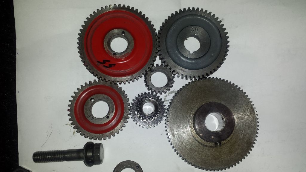
                                                  Evening John and Hopper, the plot does indeed thicken as I've just been in the garage for a closer look at the tumbler reverse and it turns out that all the gears currently fitted to the lathe are Mod1. I've taken the little compound gear off the tumbler to compare it to the standard 20dp change gears and the difference is so obvious I'm surprised I hadn't noticed before. Also that grey 50t gear i just bought of a certain Myford seller on eBay looks a bit p1ssed to me lol20160525_181106.jpg

                                                  I'll go back into the garage and get you that pic of the tumbler reverse set up you asked for.

                                                  #240299
                                                  Richard Hardcastle
                                                  Participant
                                                    @richardhardcastle

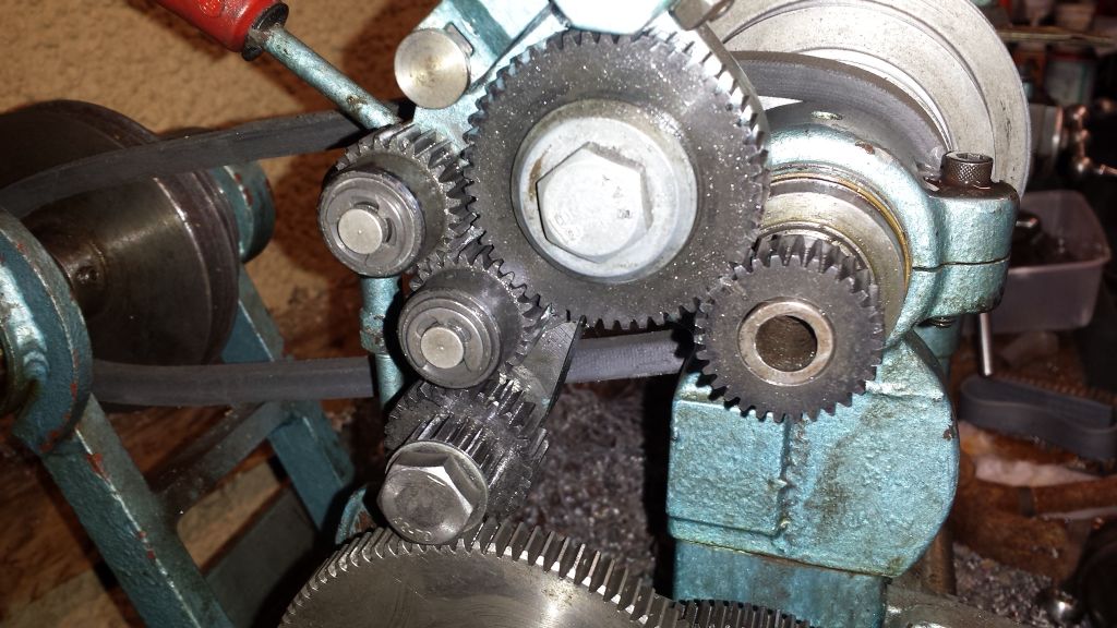
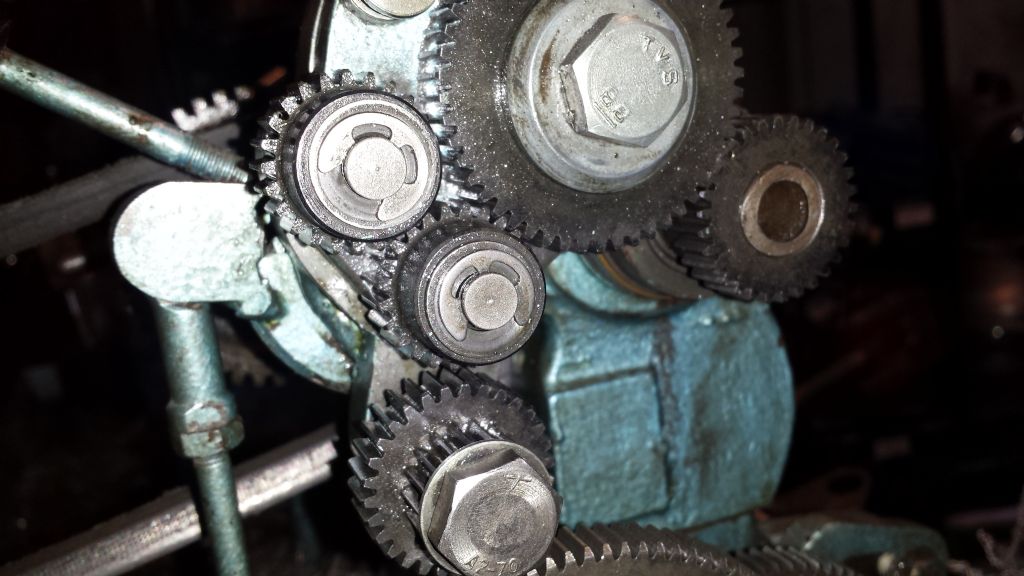
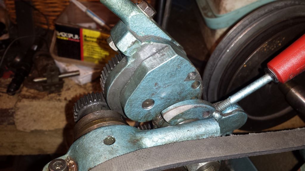
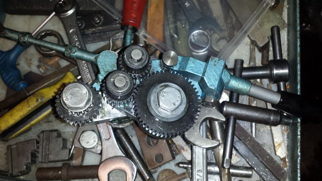
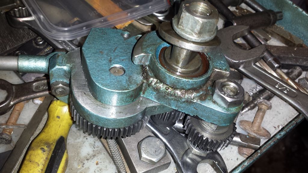
                                                    Here are the photos of the reverse tumblers . I think my quadrant may be different as well as in other photos of peoples ML lathes they have a quadrant with 2 slots arranged in a sort of V where as mine just has the single slot. I don't know if that will matter but there are plenty on ebay if I need the V type.

                                                    20160525_184026.jpg

                                                    20160525_184033.jpg

                                                    20160525_184045.jpg

                                                    20160525_184112.jpg

                                                    20160525_184144.jpg

                                                    The black handle selects forward, reverse or not engaged, the red handle just tightens the v belt.

                                                    #240341
                                                    Andy Ash
                                                    Participant
                                                      @andyash24902

                                                      I have an old ML4 which is very similar to that, and I'm sure that your change gears and mounting are very different. Someone has heavily modified your machine, but that is likely to be a good thing. The actual Myford gears were quite good, but the original method of mounting left a lot to be desired.

                                                      I don't know if all of your gears are metric or not. There's no reason not to use metric gears if that's what your machine has been converted to use. The main thing of importance is that all the gears you use have the same pitch.

                                                      Don't forget that idler gears can be anything. An easy way to think about this is one tooth in, one tooth out. The only way you get a change is to have two gears on one shaft. Then you certainly don't get one tooth in one tooth out.

                                                      Your lead screw is probably 8 TPI, but that might have been changed too. If it is 8TPI then the 20T and 50T gears sound right for 20TPI. Just use whatever idlers bridge the gap. It looks like you have a tumbler reverse, so you can have odd or even numbers of idlers, as you find convenient.

                                                      Edited By Andy Ash on 25/05/2016 23:18:47

                                                    Viewing 25 posts - 1 through 25 (of 33 total)
                                                    • Please log in to reply to this topic. Registering is free and easy using the links on the menu at the top of this page.

                                                    Advert

                                                    Latest Replies

                                                    Home Forums General Questions Topics

                                                    Viewing 25 topics - 1 through 25 (of 25 total)
                                                    Viewing 25 topics - 1 through 25 (of 25 total)

                                                    View full reply list.

                                                    Advert

                                                    Newsletter Sign-up