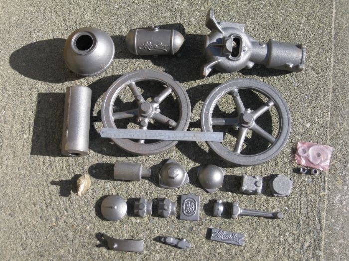
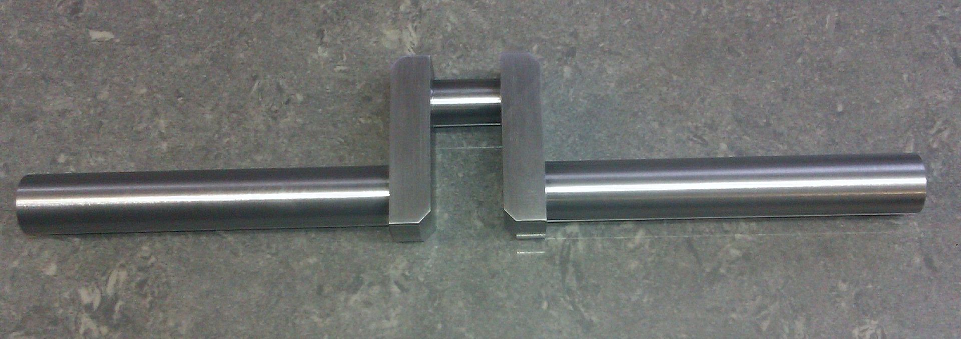
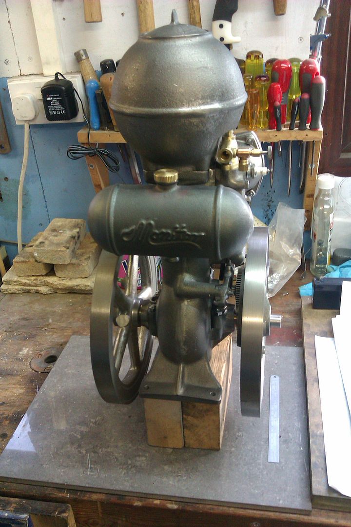
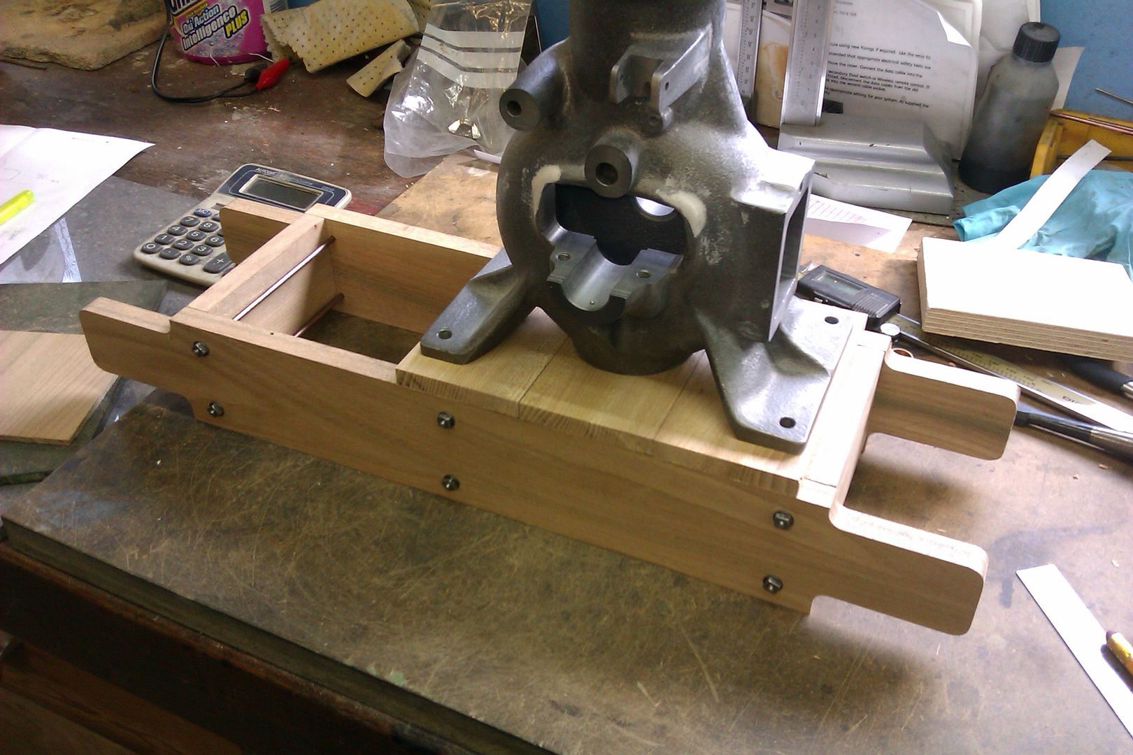
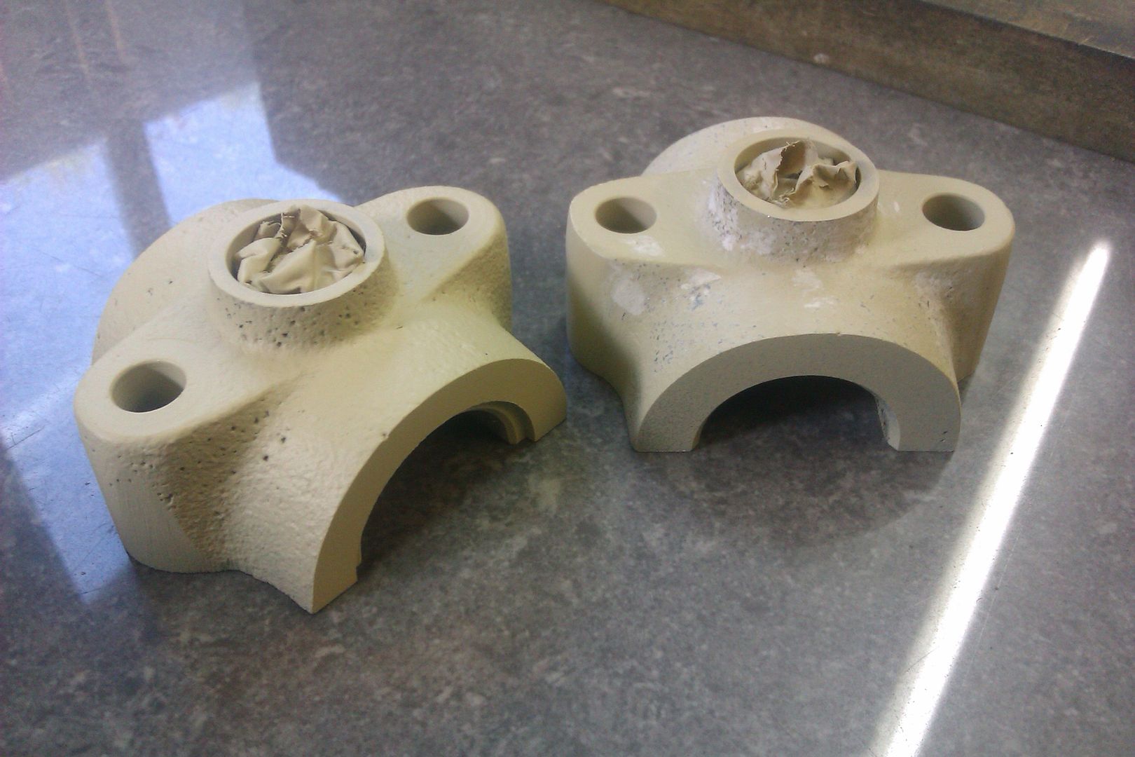
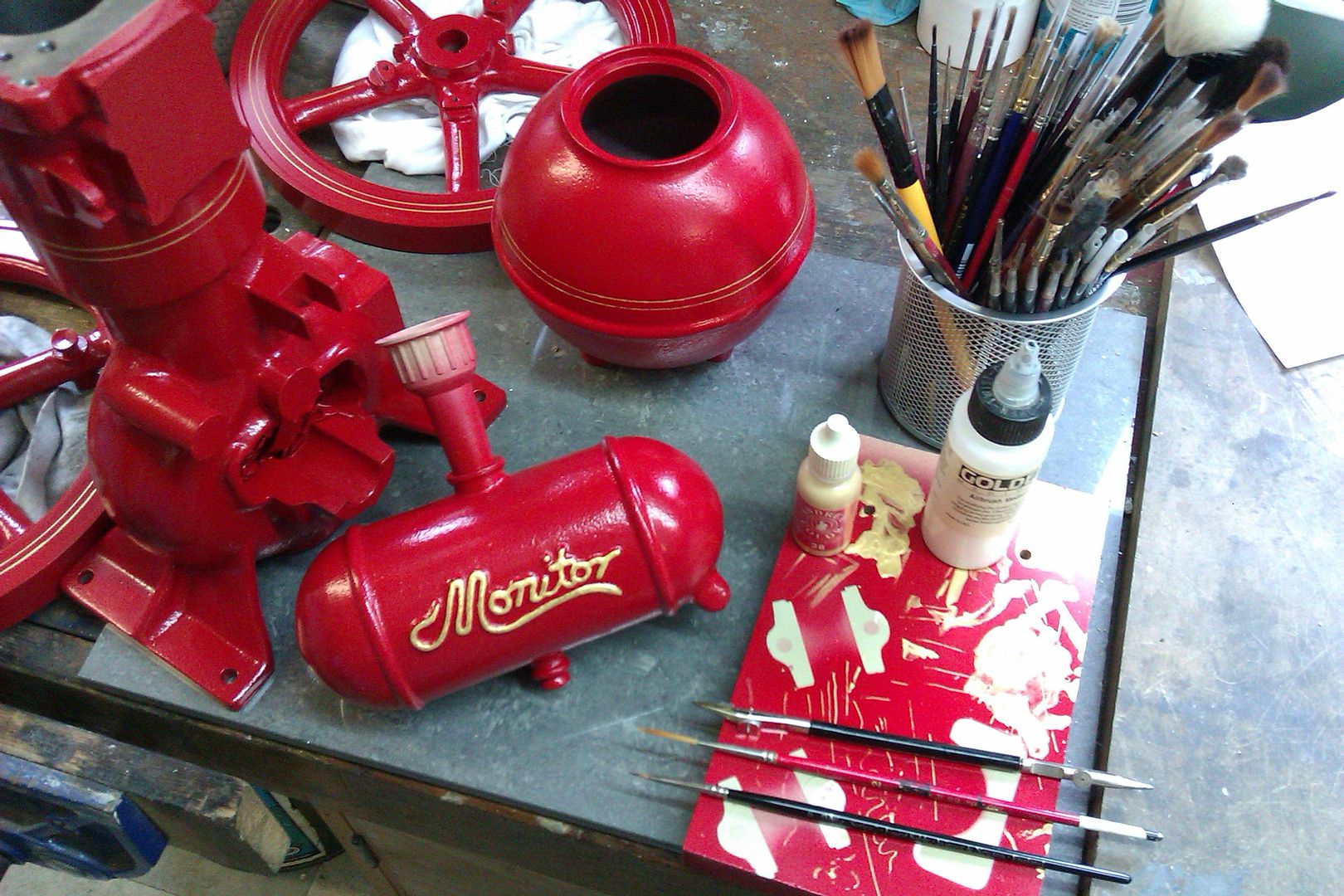
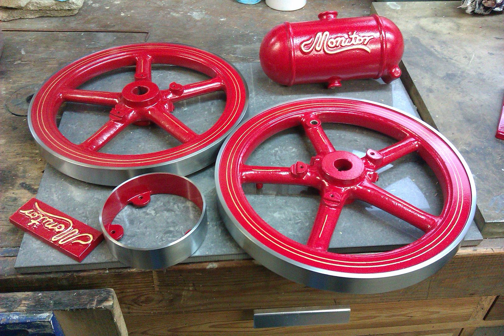
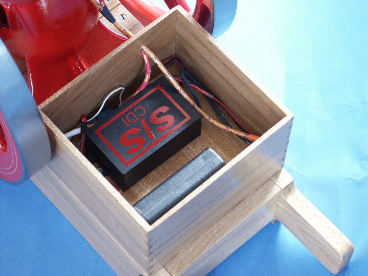
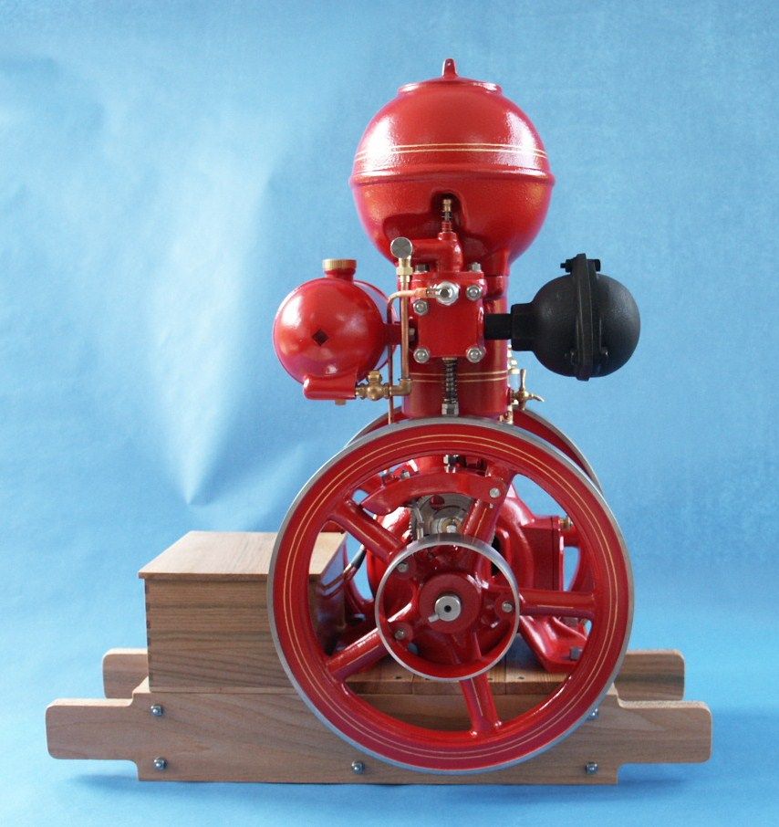
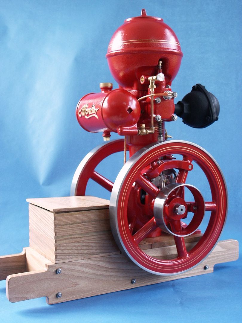
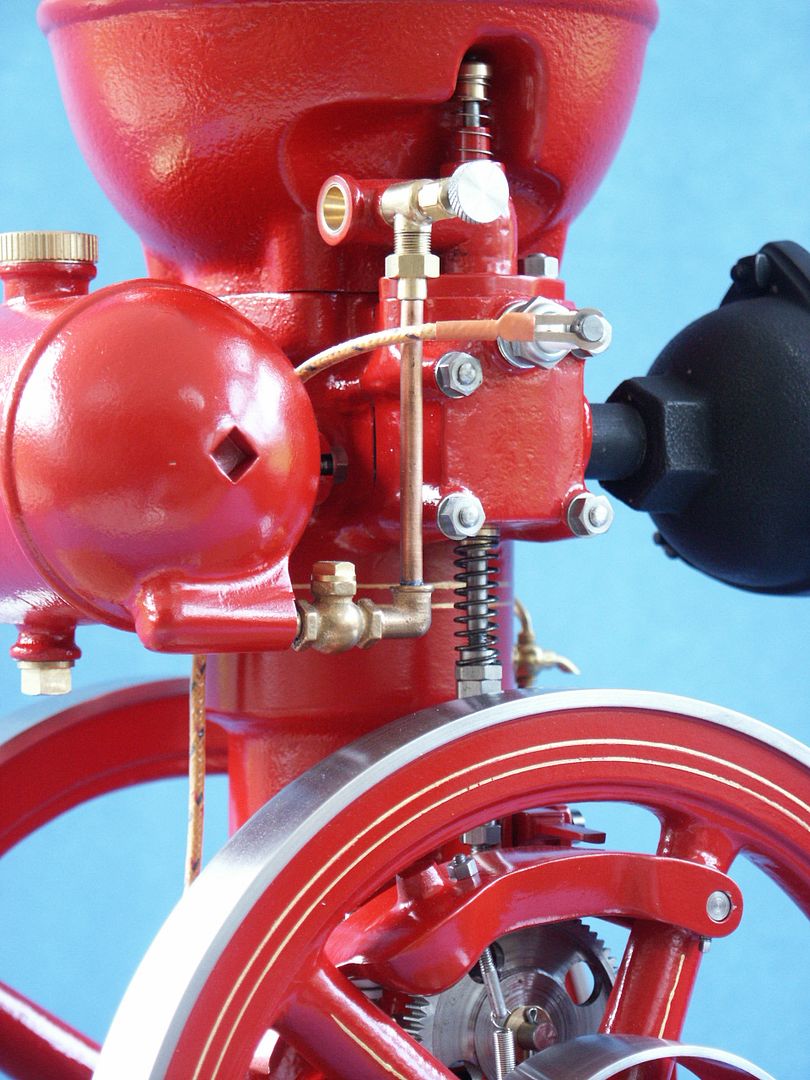
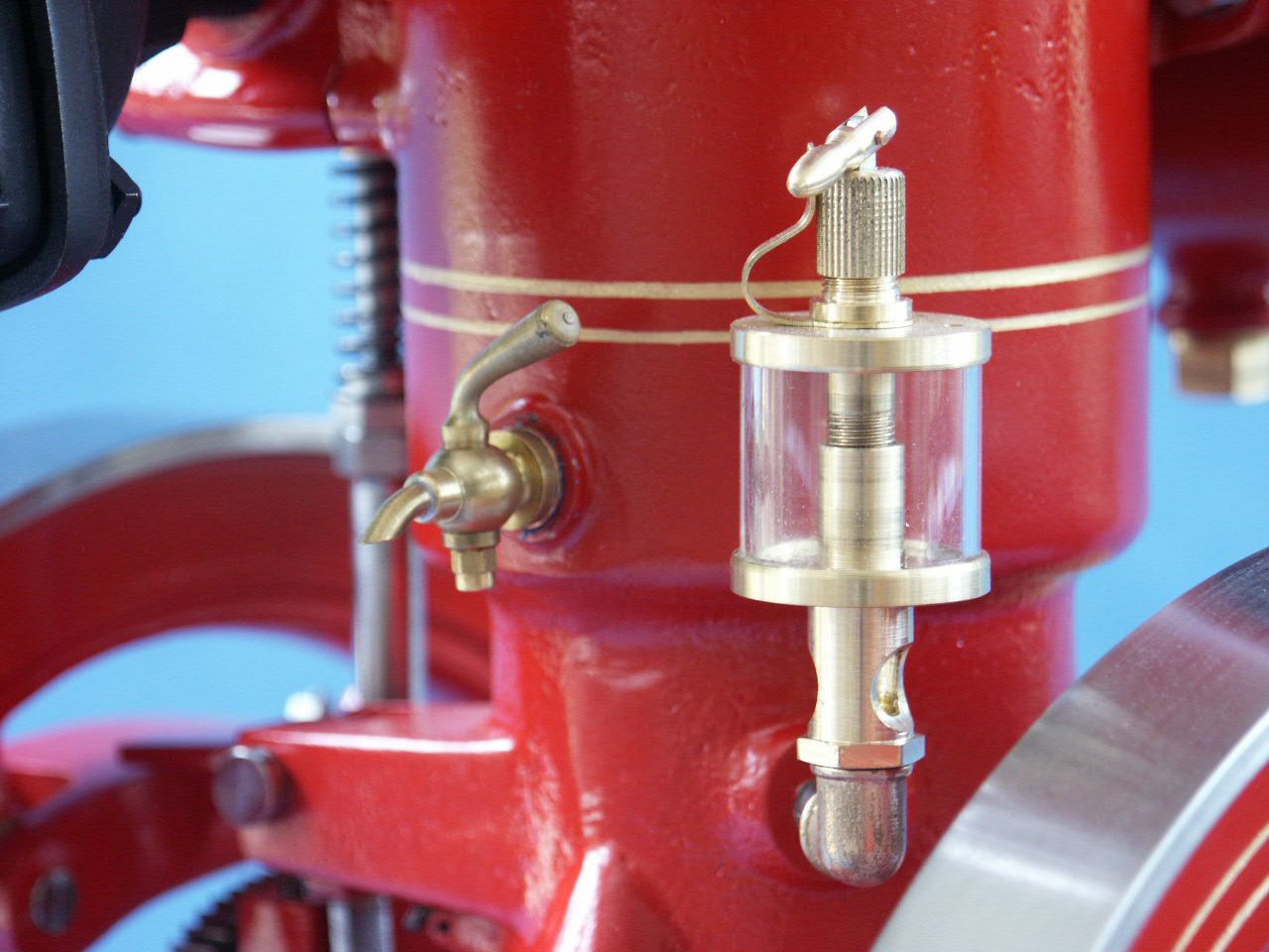
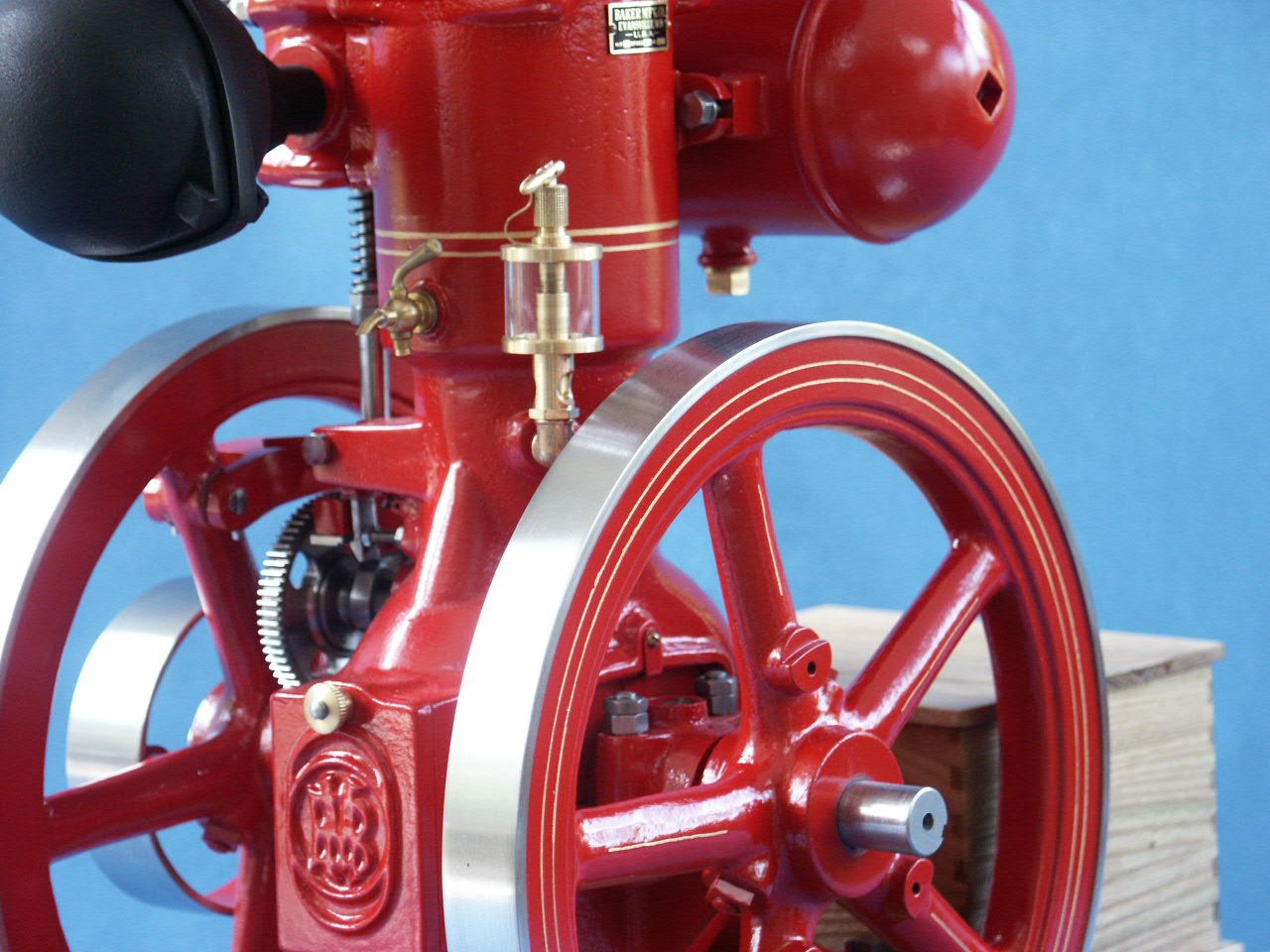
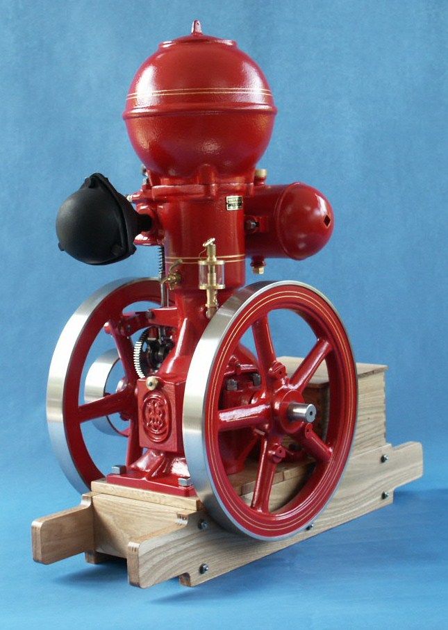
1/3rd Scale “Ball Hopper” Monitor Build
1/3rd Scale “Ball Hopper” Monitor Build
- This topic has 26 replies, 7 voices, and was last updated 19 September 2023 at 11:03 by
 JasonB.


 ]
]


- Please log in to reply to this topic. Registering is free and easy using the links on the menu at the top of this page.
Latest Replies
-
- Topic
- Voices
- Last Post
-
-
blackgates eng
1
2
Started by:
Peter Daw
in: Beginners questions
- 21
-
28 July 2026 at 12:03
JasonB
-
Basic(?) Milling question
Started by:
paulmichael1084
in: Beginners questions
- 9
-
28 July 2026 at 11:54
JasonB
-
REXON SS16A scroll saw
Started by:
Michael Gilligan
in: Workshop Tools and Tooling
- 4
-
28 July 2026 at 11:41
Dennis R
-
It’s A Compressor, Jim, But Not…
1
2
Started by:
Nigel Graham 2
in: General Questions
- 14
-
28 July 2026 at 10:37
Nigel Graham 2
-
Is anyone interested in developping a new series of model engines?
1
2
3
4
Started by:
paulmichael1084
in: General Questions
- 20
-
28 July 2026 at 10:31
paulmichael1084
-
Sealed Lead-Acid Battery
Started by:
Michael Gilligan
in: Electronics in the Workshop
- 4
-
28 July 2026 at 10:03
Michael Gilligan
-
Garden water pump
Started by:
John MC
in: The Tea Room
- 12
-
28 July 2026 at 09:42
noel shelley
-
Boiler explosion on Guadeloupe.
Started by:
howardb
in: The Tea Room
- 6
-
28 July 2026 at 09:36
vintagengineer
-
Latest new addon for FreeCAD!!
Started by:
Russell Eberhardt
in: CAD – Technical drawing & design
- 2
-
28 July 2026 at 08:51
Russell Eberhardt
-
All things Beaver Mill
1
2
…
9
10
Started by:
Robert James 3
in: Manual machine tools
- 43
-
28 July 2026 at 07:51
Lex Davis
-
Silver Soldering
Started by:
Jss
in: General Questions
- 11
-
27 July 2026 at 23:36
duncan webster 1
-
Bengs kits
Started by:
paul1956
in: Beginners questions
- 5
-
27 July 2026 at 17:37
duncan webster 1
-
New motor for a Myford super 7
Started by:
Hollowpoint
in: Electronics in the Workshop
- 12
-
27 July 2026 at 17:29
john fletcher 1
-
chester conquest pcb board connections
Started by:
In Wilson
in: Introduce Yourself – New members start here!
- 6
-
27 July 2026 at 13:35
Hugh Stewart-Smith 1
-
Peat-Shaped [ ref. Verdict DTI ]
Started by:
Michael Gilligan
in: Workshop Tools and Tooling
- 1
-
27 July 2026 at 12:40
Michael Gilligan
-
Plug in Solar
1
2
3
4
Started by:
Vic
in: The Tea Room
- 28
-
27 July 2026 at 09:27
not done it yet
-
Super Simplex Build
Started by:
Peter Hoerlein
in: Work In Progress and completed items
- 7
-
27 July 2026 at 06:29
Peter Hoerlein
-
Hobbing a Brass or Aluminium Drive Pulley to Stop Belt Slippage
Started by:
Blue Heeler
in: Hints And Tips for model engineers
- 7
-
27 July 2026 at 00:45
Blue Heeler
-
Long awaited FreeCAD version 1.1 released
Started by:
Russell Eberhardt
in: CAD – Technical drawing & design
- 3
-
26 July 2026 at 15:36
Russell Eberhardt
-
Looking for detailed build logs to help decide next project
Started by:
GrahamS
in: Stationary engines
- 4
-
26 July 2026 at 10:57
GrahamS
-
Deep drilling
Started by:
Speedy Builder5
in: Workshop Techniques
- 12
-
26 July 2026 at 07:58
Dalboy
-
Buzz Ballz packaging “unrecyclable” in U.K.
Started by:
Michael Gilligan
in: The Tea Room
- 6
-
25 July 2026 at 23:16
Bazyle
-
My week this week! My workshop videos
1
2
…
12
13
Started by:
Phil Whitley
in: The Tea Room
- 16
-
25 July 2026 at 19:23
Phil Whitley
-
Mysterious Morse Tapers
Started by:
Pippin
in: Workshop Tools and Tooling
- 10
-
25 July 2026 at 17:12
Pippin
-
Posts by new member containing ads.
Started by:
alecs
in: Website Questions, Comments, and Suggestions
- 5
-
24 July 2026 at 20:22
bernard towers
-
blackgates eng
1
2
Latest Issue

Newsletter Sign-up
Latest Replies

