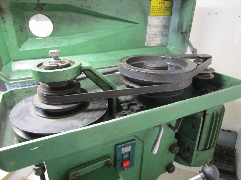
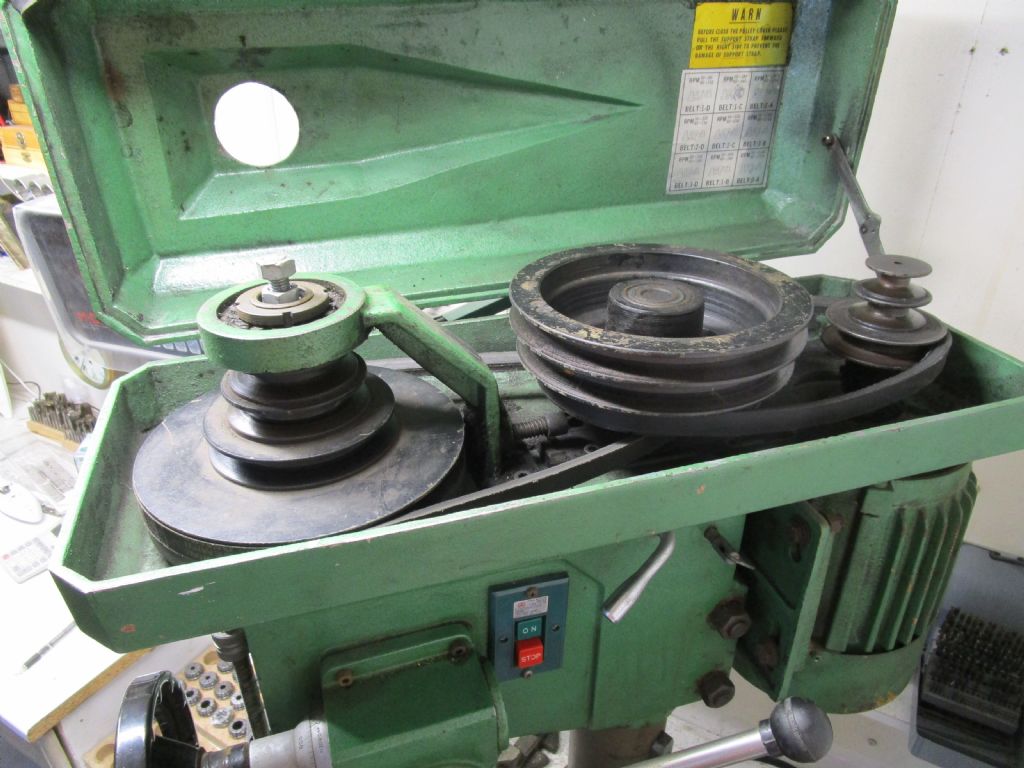
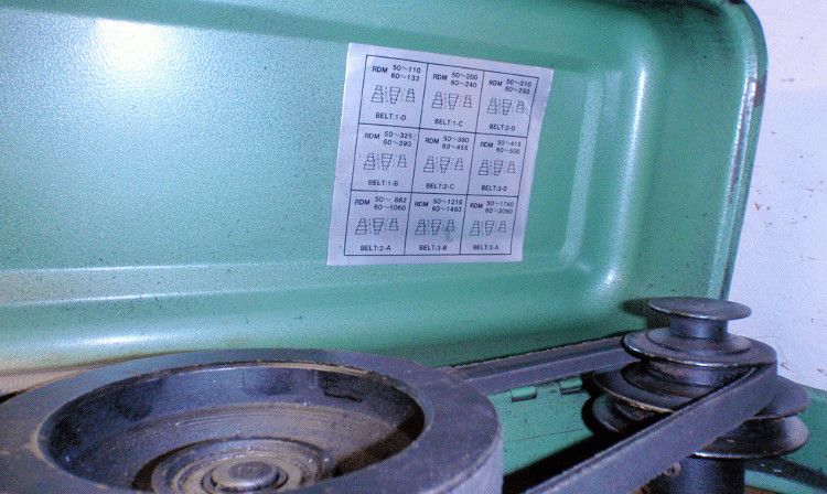
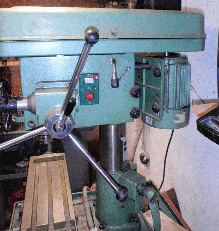
Belt problems with an Alpine DM25
Belt problems with an Alpine DM25
- This topic has 9 replies, 5 voices, and was last updated 1 June 2020 at 22:18 by
old mart.
Viewing 10 posts - 1 through 10 (of 10 total)
Viewing 10 posts - 1 through 10 (of 10 total)
- Please log in to reply to this topic. Registering is free and easy using the links on the menu at the top of this page.
Latest Replies
Viewing 25 topics - 1 through 25 (of 25 total)
-
- Topic
- Voices
- Last Post
Viewing 25 topics - 1 through 25 (of 25 total)
Latest Issue
Newsletter Sign-up
Latest Replies
- Sourcing Dexion SpeedFrame beam section
- Hello.
- End Mill Sharpening Jig
- Mercer comparator gauge repair help.
- Warco Super Major Milling Machine – Stripping Gearbox
- interchangeable Myford beds
- Modular 3/4 inch TE info required
- Weird electric actuator action
- Painting mating surfaces
- 125 mm chuck onto my lathe


