What Did You Do Today 2019

Advert

What Did You Do Today 2019

Home Forums The Tea Room What Did You Do Today 2019

Viewing 21 posts - 1,026 through 1,046 (of 1,046 total)
  • Author
    Posts
  • #443531
    Anonymous

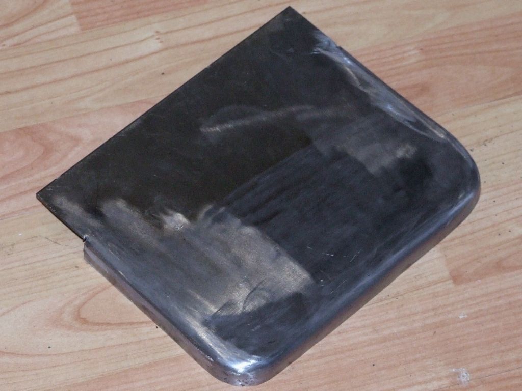
      Forming the real spectacle plates was a mixed bag. One total bog up and one that looks ok. Here's the one that looks ok, after trimming the flanged rim to roughly the right depth on the mill:

      spectacle plate me.jpg

      I've also learnt some valuable lessons about flanging allowances that should make the remaining plates easier. I've run out of oxygen and acetylene so that'll have to be in the New Year.

      Tomorrow I'll go up to the gliding club for a fettling session with angle grinder and power drill on the cylinders and supporting castings prior to machining.

      Andrew

      Advert
      #443533
      Dalboy
      Participant
        @dalboy
        Posted by Jim Nic on 27/12/2019 19:59:50:

        Derek

        Your hearth looks just like the one I got from CuP Alloys a few years ago which I find ideal for the small jobs I do and has served me well.

        I don't use the fluffy blanket, I found that parts moved on it too easily while I was applying heat and solder. I got an extra piece of hearth brick and cut a few strips on which to place my unsoldered assemblies for heating.

        Jim

        That is where this came from the mat is just laid in there. I did think of getting a couple more bricks maybe in the future

        #443537
        Paul Lousick
        Participant
          @paullousick59116

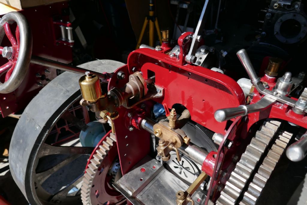
          More work on my traction engine, making lagging covers for the boiler.

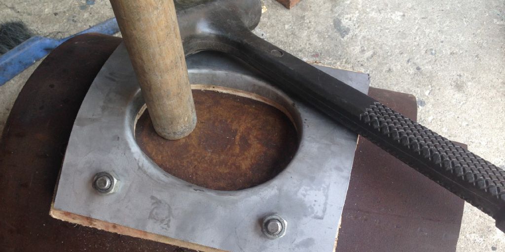
          Temporary templates cut out of cardboard first to get an exact fit around the steam chest and boiler fittings, then cut out of steel sheet. The flange for the manhole made by bashing the metal sheet around a former attached to a piece of left over boiler tube with a bronze bar and hammer.

          lagging 2.jpg

          lagging 1.jpg

          Manhole flange attached by screws will be replaced with rivets.

          Paul

          #443656
          Anonymous

            The spectacle plate now fits:

            spectacle plate in situ.jpg

            But I'm not happy. It doesn't match the picture in my mind of how it should look, so it isn't acceptable. It feels a bit like a school report – in my case they normally said "could do better" or "could work harder". I haven't given up on flanging yet, but ultimately I'll weld a flange onto a plate rather than trying to form it hot.

            Andrew

            #443670
            JasonB
            Moderator
              @jasonb

              Thought you might CNC it from solidwink

              Another alternative may be to do it as three straight bends and then weld in separate corners or ,make several radial cuts in the corners and bend the smaller parts over then fill in the saw kerfs with weld and dress. I did the later on teh fowler where the side jogs in to allow for the thickening plate around 3rd shaft and axle.

              #443689
              Perko7
              Participant
                @perko7

                Took my nearly completed 5in gauge petrol-powered loco out to the club family day for it's second test run. Not entirely successful. While it would easily propel itself, attaching a riding car proved too much. First the gearbox would refuse to stay engaged, there is too much play in the bushes for the overhanging drive shaft, allowing the gears to move apart under load and skip teeth. Worse in forward gear than reverse, so left it in reverse and tried again. Now found the load too much for the existing centrifugal clutch. A bit of a push saw it get going but it eventually ground to a stop on the grade up into the station. Oh well, only minor issues which can be rectified without too much work. Final straw was a grub screw on the gear change shaft coming loose which meant it was now stuck in reverse. At least I now know it runs, and runs very smoothly, and has plenty of speed, just need to get more of that 25cc of raw power to the wheels!

                #443723
                Nick Wheeler
                Participant
                  @nickwheeler

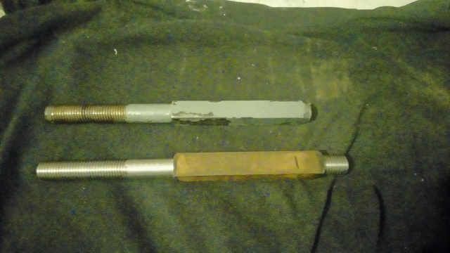
                  Not the most exciting part, a length of 25 steel bar threaded M20 on each end:

                  oldandnewheadbolts.jpg

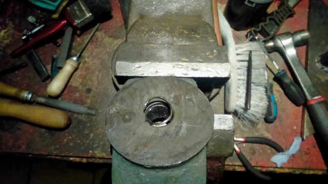
                  it took ages to drill, mill, file and heat the Loctite(30minutes on the stove while I had lunch) to unwind the broken off thread

                  unwindingthread.jpg

                  and the whole assembly stopping the freezer floating away:

                  repairedclapper.jpg

                  It was quite exciting when that fell out of the bell on Monday…….

                  #443812
                  Paul Lousick
                  Participant
                    @paullousick59116

                    Andrew,

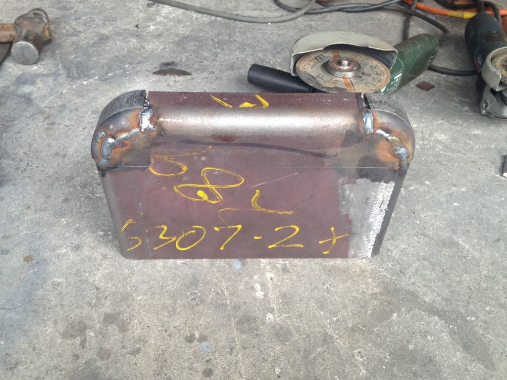
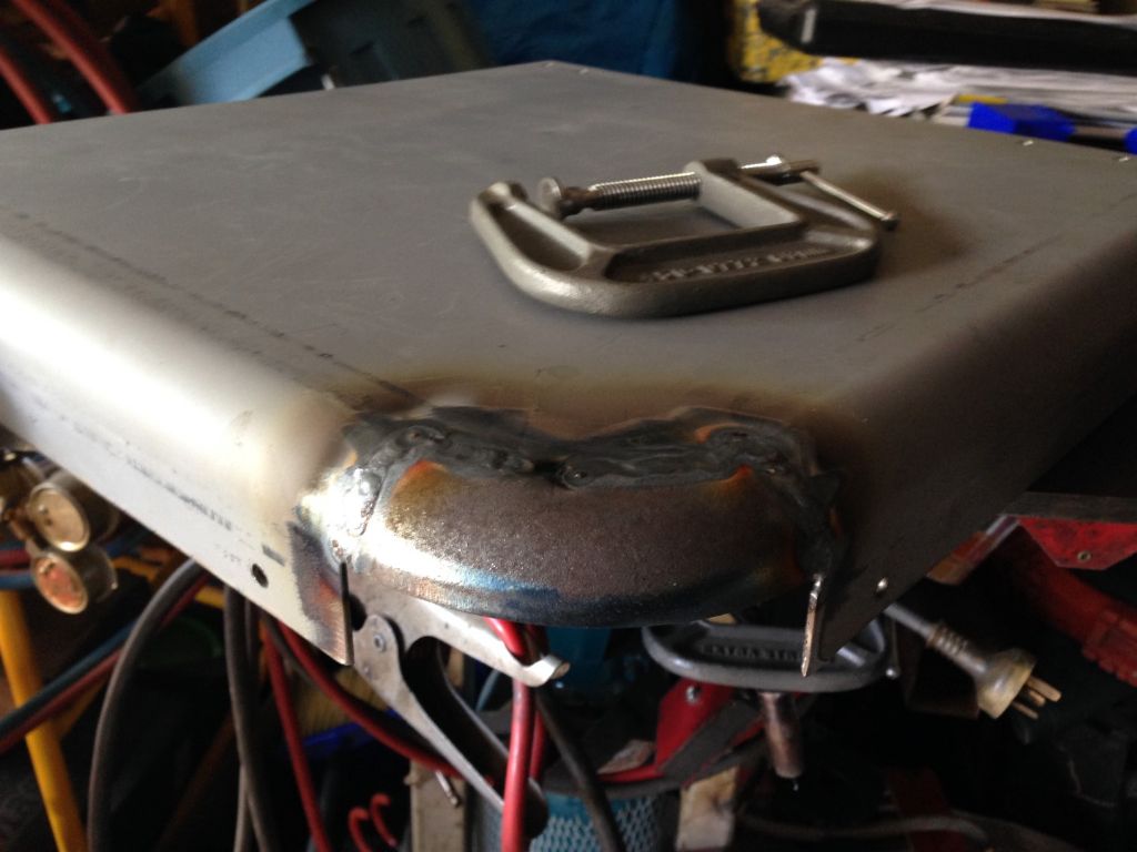
                    I made the spectacle plates on my engine by bending the 3 sides around a suitable former in a press and then welding in a segment of a pipe elbow (the flange radii bent to match the pipe elbow). Then a bit of grinding to smooth out the welds.

                    weldment.jpgp1010668.jpg

                    I also made the rounded corners on the tender in a similar way. (see below)

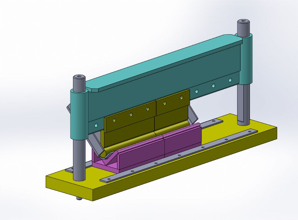
                    Achieving an accurate finished size to the outside of the flanged sides is the trickiest part as bending is one of the least accurate fabrication methods. I used Solidworks to model the plates in 3D which is able to prodice a drawing in the flattened state and show an exact position of the bend line for positioning under the press.

                    Paul.

                    press brake with front plate.jpgtender corner.jpg

                    Edited By Paul Lousick on 29/12/2019 22:14:49

                    #443850
                    Anonymous

                      Paul: Thanks for the pictures; that's a neat looking job. It'll be a fallback for me if I fail to flange properly. I'm going to have at least one more go at flanging. The existing plate isn't bad, but in retrospect I didn't get all of the flanges close to the former. That's partly my own fault for finishing late at night when it was dark, and I was running out of gas. On reflection I feel that I'm pretty near to getting flanging to work to an acceptable standard. The fullsize engines aren't perfect; so as long as I match them I'll be happy. I've also learnt that I can cut down on my allowance for the flanging which should make life easier. Especially on the corners where the excess metal causes the flange depth to grow. I've designed for a 3/4" flange and allowed 1", the excess being machined off. I can cut the allowance down to 7/8" and for the corners I can go down to 3/4" or even slightly less. Roll on the New Year when I can get some more gas!

                      In the meantime I'm knocking out the 1/4" BSF bolts and another batch of nuts on the Britan that I'll need to fix the plates.

                      Andrew

                      #443861
                      Paul Lousick
                      Participant
                        @paullousick59116

                        Bending the flanges was quick and easy. The front spectacle plate was 2mm under size over the flanges after bending and was packed out with a 1mm shim on both sides. The rear plate was exactly to size. The biggest job was designing and making the press brake and form tools to match the inside radius of the flanges.

                        Good luck with your build Andrew,

                        Paul.

                        #443877
                        not done it yet
                        Participant
                          @notdoneityet

                          It was quite exciting when that fell out of the bell on Monday…….

                          Wait being ‘campanologised’ at the time? Could have given someone a headache – not just you to fix it!

                          #443900
                          Meunier
                          Participant
                            @meunier

                            qte It was quite exciting when that fell out of the bell on Monday……unqte

                            especially at the speed it must have been travelling at, going like the clappers, as they say.
                            DaveD

                            #443956
                            Nick Wheeler
                            Participant
                              @nickwheeler
                              Posted by Meunier on 30/12/2019 15:34:02:

                              qte It was quite exciting when that fell out of the bell on Monday……unqte

                              especially at the speed it must have been travelling at, going like the clappers, as they say.
                              DaveD

                              Bells don't turn particularly quickly, and this is a small one. The clapper made a racket as it hit the frame and then the floor. What's slightly disappointing is that it's only twenty years old; the oldest was cast in 1588 and still going strong.

                              #443960
                              Lainchy
                              Participant
                                @lainchy

                                I had a play with some Beta 1 case hardening compound. Has anyone used it? I have a small crank pin to case harden, and the S50 Eccentric Sheave.

                                The crank pin I gave two blasts with MAPP gas, and shook the part in a metal tin of it. It definitely left a tough skin, but being a small part it cooled rapidly. I heated it again and quenched it in water.

                                It's the sheave that I want the case hardening on really, and I guess its not critical anyway, but nice to have a play.

                                #443984
                                Nigel Graham 2
                                Participant
                                  @nigelgraham2

                                  I resumed fitting the 3-axis DRO to the Myford VMC MIll.

                                  I have had the long- and cross- travels working for some time now, and assembled the vertical one this afternoon.

                                  The magnetic strip and its holder are on a length of 2x2x0.25" aluminium angle held top and bottom by M8 studs and nuts screwed into the machine column. After a frustrating half-hour or so trying to align it by DTI, I twigged why it was so difficult (two fulcra in slots a long way apart, on a column not made to hold these devices), and used my best square instead to set it right to the table. That did the trick, according to a subsequent dial test, giving a run-out nicely <0.01" over the 8" or so of travel: I didn't push my luck by trying for the last few thou. That would entail making and fitting proper screw-adjusters.

                                  Setting the gaps between the encoder and strip was simple: I gently held the encoder while tightening the screws, against a plastic "feeler-gauge" of appropriate thickness – a strip cut from an expired caving-association membership card. It's surprising how one hobby can help another despite no obvious connection!

                                  I've still to sort out the cable supports / strain-relief, and fit the swarf-guard to the strip holder, but it's all basically finishing touches now.

                                  It's been a lengthy task, involving a lot of complicated bracket-making and losing the table's long-travel limit stops.

                                  Incidentally, I keep the console clean simply by keeping the Cellophane bag from its original packaging, loosely over it. Not tightly because although the electronics do not generate much heat I still want them able to lose that. I've long kept the workshop calculator in a polythene bag for the same reason.

                                  Next up for the milling-machine is its 3ph conversion. I have the motor etc., just need to get on with it! I don't yet know if it will entail altering or replacing the motor plate.

                                  That and sorting out why the quill rise and fall is so stiff it offers no sensitivity for drilling, and won't spring back up. My suspicion is congealed grease, but the innards are hard to reach and I am very, very wary of quill springs.

                                  At some point between buying the machine and transporting it home in pieces, then moving house without yet erecting the mill, I lost the draw-bar for its R8 spindle. However, silver linings and things: I discovered I could make a self-ejecting version, and that extra work has certainly paid off. A lot better than clouting the top of a plain draw-bar to loosen a stuck MT3 fitting, as on my previous mill/drill.

                                  ++++

                                  My friend appreciated the humorous "cake square" I'd made for her as a Christmas present – she has an endearing quirk of cutting any slice of cake into neat little cubes.

                                  ===

                                  The DRO task made a change from trying to sort out the travelling-hoist runways, and is a project I should have finished a long time ago.

                                  #444016
                                  Anonymous

                                    Paul: Thanks for the additional information. I'm hoping to avoid packing, but if needs must!

                                    This morning I've finished a batch of ~70 1/4" BSF nuts. For each nut chamfer the underside to remove the parting off burr and then tap. Took about 15 seconds per nut. Next job, in the New Year, will be to finish off the heads on the corresponding bolts but that will needl a change of collet.

                                    Andrew

                                    #444034
                                    Windy
                                    Participant
                                      @windy30762
                                       
                                      At long last am at a stage to test run on compressed air.
                                      Unfortunately my compressor does not have capacity and high enough pressure.
                                      Going on my experience with flash steamers will need at a least 150psi and a lot of air my petrol head friend at work has a screw compressor and 150psi so in the New Year will see what happens.
                                      At 120psi it’s so near continually running and a sharp exhaust noise on air.
                                      With high pressure superheated steam could be an interesting noise.
                                      It has a variable compression release valve to ease starting but flattens my air supply.
                                      Will finish welding the exhaust manifold today amongst other jobs.
                                      All the best to you all for 2020.
                                       
                                       
                                      Air test 1


                                      Engine
                                      Air test

                                      Edited By Windy on 31/12/2019 12:51:53

                                      #444101
                                      John Haine
                                      Participant
                                        @johnhaine32865

                                        I've posted a couple of photos of my clock project, and today finally after nearly 360 days since acquiring some of the bones of a Synchronome I installed the clock in its new case on our kitchen wall.

                                        img_20191231_182057399_hdr.jpg

                                        Not a wonderful photo I'm afraid. The clock keeps the gravity arm and the basic chassis, but the arm is reset by a cam driven by a stepper motor. Pendulum is sensed by an opto interrupter (you can just see a little white blob which is the mounting for it below the pendulum). Swings are counted by an Arduino Nano which drives the stepper. Most of the dial is used but driven by another stepper rather than the original electromagnet. I had to make a new pendulum using a carbon fibre rod and cast iron bob since the original was missing – also a new pallet.

                                        Pendulum is impulsed every 40 swings = 80 seconds rather than the original 30 since it doesn't have to drive a count wheel, and the dial impulsed once every 9 seconds. Main reason to use stepper motors was to make the clock much quieter than the standard 'Nome.

                                        The case is made from Valchromat, a sort of engineered MDF using Melamine resin – woodword is not my forte but it's turned out OK. Though I have the original case it's not in great condition and anyway I wanted more space to reduce pendulum air loss.

                                        Before installing in the case the clock was keeping pretty good time over quite a long period, but I anticipate quite a lot of regulation as its new home is warmer and the pendulum amplitude will be a bit less. Now I can think about the next project!

                                        #444106
                                        not done it yet
                                        Participant
                                          @notdoneityet

                                          Wellll, I just removed the table (with power feed) from my Centec 2B. 2 man job, really – according to Dave SOD – but easily accomplished even with no bench space (and not much floor space either).

                                          I was going to remove it and the cross slide as one piece, but was not able to get the cross slide gib out. Nearly sorted that and I expect to get it out tomorrow, then set about the feed screw nut, which needs attention.

                                          Not far off the weight of a mini lathe, possibly more I think.🙂 So not too bad for an over 70 with a quad bypass.

                                          #444108
                                          old mart
                                          Participant
                                            @oldmart

                                            I reversed the house phone connection as the incoming supply has moved from one side of the living room to the other. The wiring around the skirting, under the carpet across a door frame was too much for me to change, but looking through my many phone cables and changing one end plug, with a check first with a meter, it works, hooray and a happy new year to all.

                                            #444110
                                            Steviegtr
                                            Participant
                                              @steviegtr

                                              20191231_223123.jpgStripped the lathe ready for new belts & an inverter/3ph motor.

                                              20191231_223116.jpg

                                              Edited By Steven Edwards 1 on 31/12/2019 22:53:48

                                            Viewing 21 posts - 1,026 through 1,046 (of 1,046 total)
                                            • Please log in to reply to this topic. Registering is free and easy using the links on the menu at the top of this page.

                                            Advert

                                            Latest Replies

                                            Home Forums The Tea Room Topics

                                            Viewing 25 topics - 1 through 25 (of 25 total)
                                            Viewing 25 topics - 1 through 25 (of 25 total)

                                            View full reply list.

                                            Advert

                                            Newsletter Sign-up