What Did You Do Today (2017)

Advert

What Did You Do Today (2017)

Home Forums The Tea Room What Did You Do Today (2017)

Viewing 25 posts - 1,901 through 1,925 (of 2,518 total)
  • Author
    Posts
  • #315461
    thaiguzzi
    Participant
      @thaiguzzi
      Posted by mark smith 20 on 04/09/2017 19:00:56:

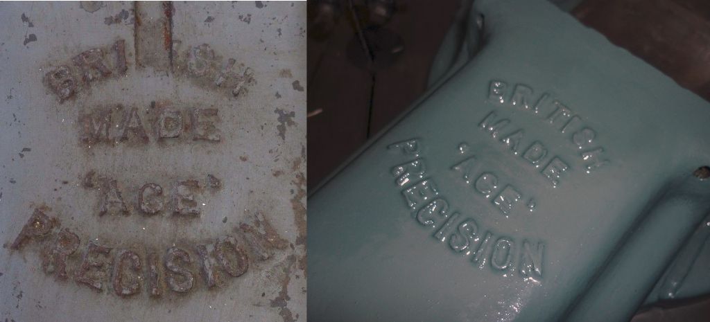
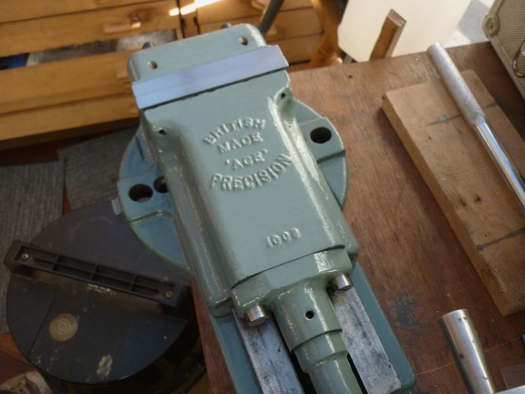
      Got the vice together apart from jaws, stoned all the dings /burrs of all the slideways, had to make new jib strip . Also

      put the `t` back in British.smiley The vice opens an closes pretty stiffly ,almost impossible by hand but easy with a handle. I suppose tighter is better where milling is concerned.

      untitled-1.jpg

      Very nice job!

      Advert
      #315462
      thaiguzzi
      Participant
        @thaiguzzi

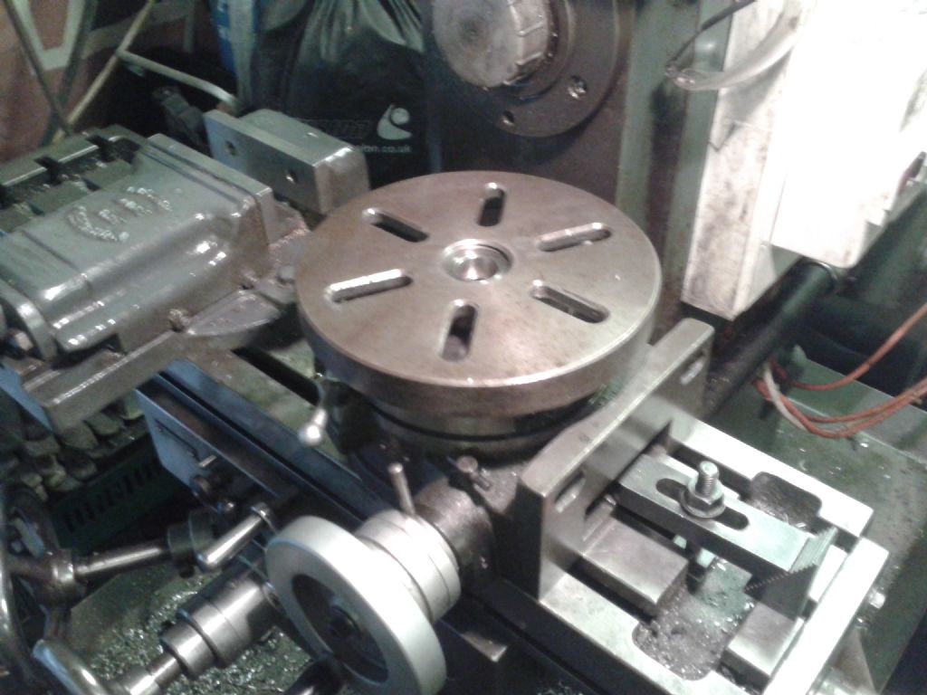
        Found a better photo. Same colour as yours, bot not so pretty.

        I seem to remember I shortened the body too, due to a corner being broken off.

        phone photos to sept 2017 537.jpg

        #315468
        Joseph Noci 1
        Participant
          @josephnoci1

          Hi there Bob Rodgerson,

          Interesting stuff you are doing..I do not have a good idea of the scale of that construction for the gang tooling mechanism – it looks quite hefty with material thicknesses in the 10s of millimeters? 20mm? Not sure..

          However, just a comment on the welding (!) It does appear that welding is purely superficial, providing no structural strength…Was it MIG or Stick? Whatever method, the weld current was WAY to low- no penetration – could have been doubled with good effect! If my assessment of material thicknesses is close, then to assist in preventing distortion from the much greater local heating from higher amperage welding, put the whole assembly in Her oven till around 180deg C and weld up, and let cool on its own. Maybe too late now, but those welds…

          Regards

          Joe

          #315509
          Bob Rodgerson
          Participant
            @bobrodgerson97362

            Hi Joe,

            It is a hefty construction in 20mm plate. The front plate is 6" deep X 7" long and the side plate is ^" deep x 9" long.

            The welds are much better than they look on the picture, preparation included grinding at least a 1/4" 45 degree off the edges that were to be welded this was filled with weld which took well using maximum current, what you see is my attempt to build up in the area of the weld. The biggest problem I have with welding is getting the correct setting for my welding helmet, I am either almost blinded by light or it is too dark to see anything.

            Regards,

            Bob

            #315548
            Joseph Noci 1
            Participant
              @josephnoci1

              Hi Bob,

              Ok, I get the picture..What was the Amperage setting on the welder, and was it stick or mig?

              Joe

              #315551
              OuBallie
              Participant
                @ouballie

                Back on my feet for a few hours a day now, after being attacked by the vice in the Workshop.

                Five weeks now having to have left for elevated for most of the time!

                Geoff – Frustration level at 100%

                #315556
                NJH
                Participant
                  @njh

                  Good grief Geoff

                  "…….after being attacked by vice in the Workshop."

                  I read that quickly and paused a moment – Vice in the workshop ? !! disgust now there's a thought

                  Seriously though I hope you recover soon.

                  Norman

                  #315565
                  Bob Rodgerson
                  Participant
                    @bobrodgerson97362

                    Hi Joe,

                    welder is Mig Gas/No Gas. I also forgot to add that the main box section of the attachment also has mortice & tendon type joints the edges of the mortices were given a 45 degree Chamfer to assist the welding process so basically I have no doubt as to the rigidity & strength of the structure.

                    Regards,

                    Bob

                    #316108
                    OuBallie
                    Participant
                      @ouballie

                      Thanks Norman for the wishes.

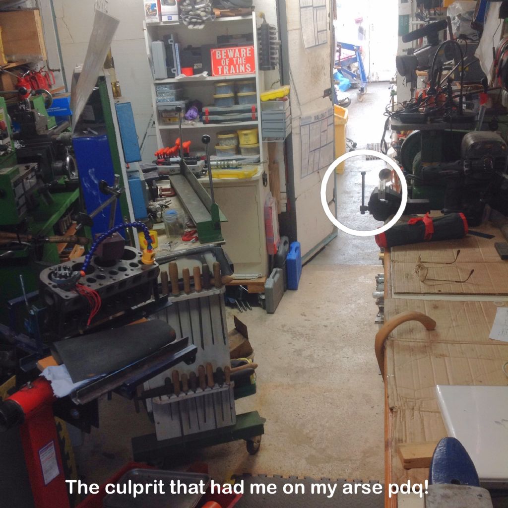
                      Here's the culprit:

                      Attacking vice

                      This is what happened:

                      Vice Attack
                      Took place in the Workshop on the 27th July 2017 at 1917h.
                      In preparation for getting the Ruby body back into the Carport I had to make space, so wheeled the MobileToolTrolley (MTT) into the Workshop, and with the engine stand in there already, it became a little cramped between the MTT and vice, meaning I had to walk closer to it as I went past.
                      As I was doing so, having taken a step forward and with right foot/leg following, the partly unzipped jumper I was wearing must have bellowed outward and got caught by the vice handle that was pointing vertically upward.
                      The result was my top half coming to a sudden halt but bottom half continuing its forward motion, and with all of my weight now on my left foot ready to move forward I found myself starting to fall backward so I did all I could in getting my left foot to stop the fall, but all that this did was to make the foot slide forward resulting in me putting even more force in trying to stop it.
                      Result being intense pain due to stretched tendons and sprained ankle, both diagnosed by a doctor, and a day later the instep turning into one big dark blue bruise, the latter causing other half's-eyes, a nurse, coming out on stalks.
                      A week later, and still hobbling around using two walking sticks I go a doctor to come have a look.
                      Prognosis was as mentioned above but nothing broken, however, 4-6 weeks of keeping foot elevated for recovery.
                      09/09/17 and am now able to put pressure on the foot, but not for the whole day yet.
                      Frustration is at 100%

                      Geoff – Had just got the Ruby body back into the Carport ready to work on it!

                      Edited By OuBallie on 09/09/2017 14:49:34

                      #316116
                      Muzzer
                      Participant
                        @muzzer

                        Finished messing with the sump, coolant pump and coolant in the CNC machine. When I removed the coolant pump, it looked as if something very big and very ill had thrown up in the sump.

                        Filthy sump

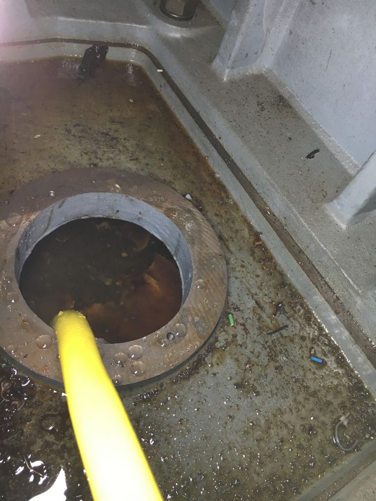
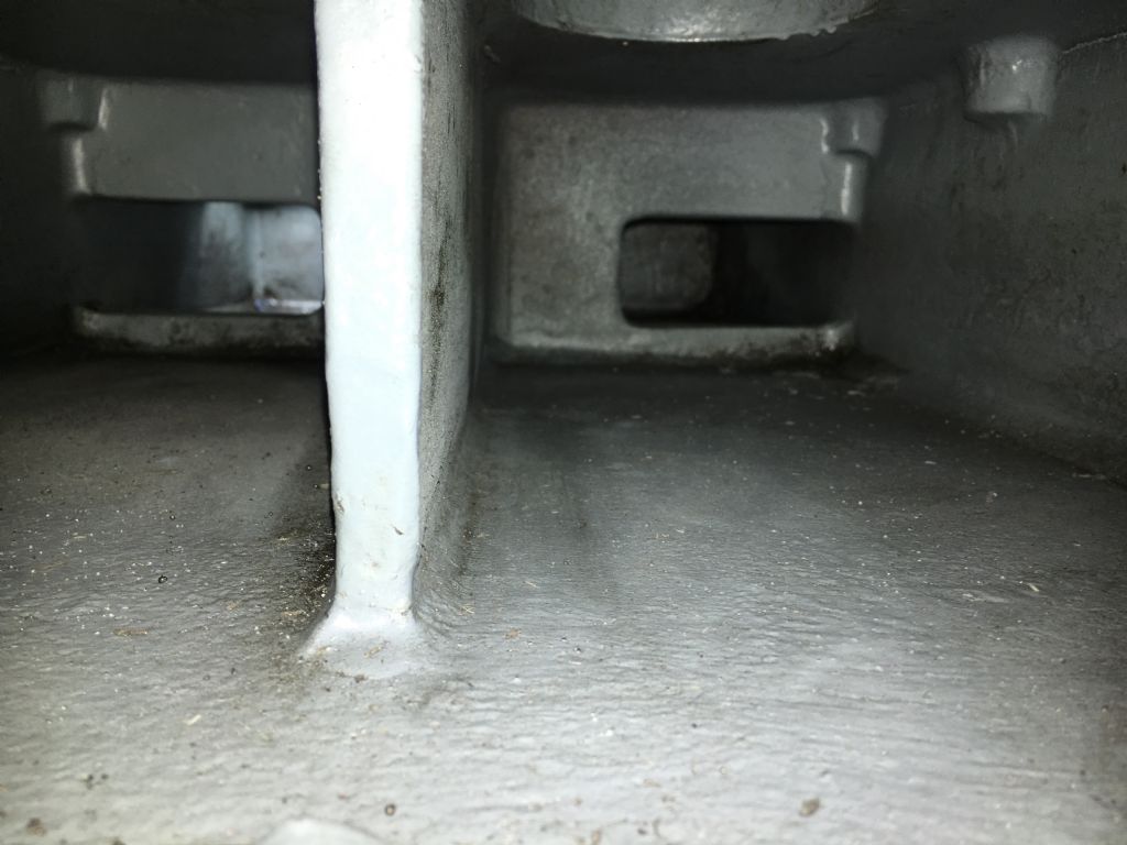
                        It took quite a bit of flushing and Gunking to clean out all the crap. Now it looks pretty good, so was time to put some new coolant in. This is what you see with the inspection cover removed, looking horizontally into the sump chamber, with the pump aperture visible at the top:

                        img_4752.jpg

                        Got some Castrol Hysol XF from Broughton Lubricants who are based not far from my place of work in Preston. Hysol XF is a soluble oil recommended for general machining operations in both steel and aluminium, so should do for my purposes. The choice of lubricants has come up in discussions on this forum previously and when I looked around in the market, Hysol XF seemed to come out well. The main issue being the minimum quantity of 20L. I need about 2L for the CNC machine and even with the lathe and Blidgeport I'll be lucky to use another 2 litres at the recommended dilution of 7%. Ah well.

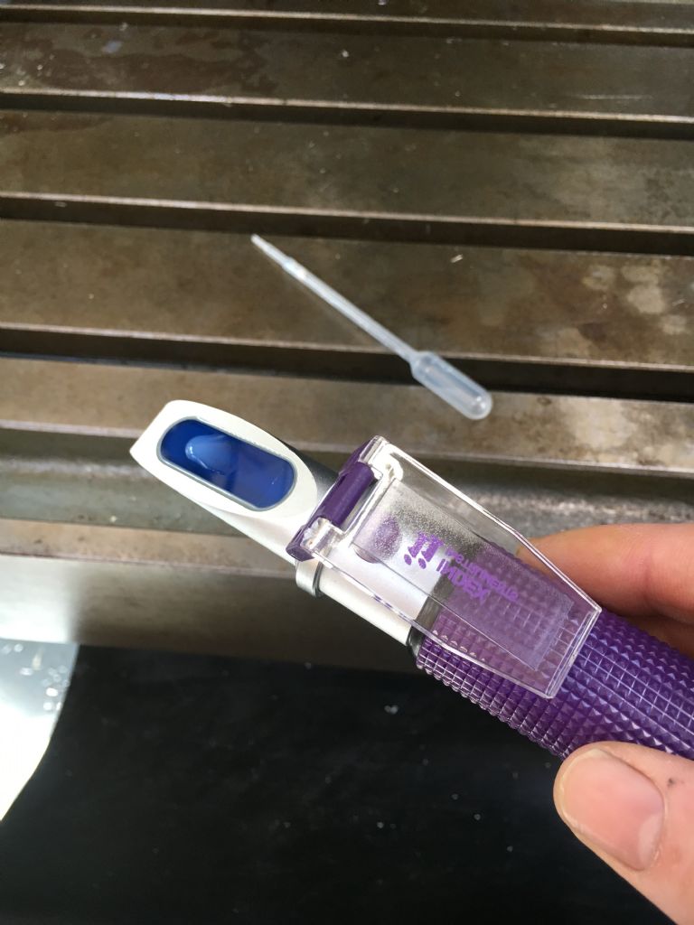
                        The recommended method to check the dilution is with a refractometer. A simple, visual refractometer is fairly straightforward to use. You place a drop of the fluid on the glass surface and lower the frosted plate onto it. The refractive index of the fluid refracts the light onto a graduated scale in the eyepiece and you can read off the dilution directly. Good explanation here.

                        Refractometer

                        The coolant pump is a 3-phase induction machine but I didn't fancy coughing up for a VFD just for that function. And the spindle motor is designed to operate over a wide range of speeds (1000-6000rpm), so not sensible to piggy back the coolant pump off the back of its VFD. Instead, I simulated the third phase using a 8uF motor run cap from Maplin.

                        This scheme is a bit of a compromise. Once up and running, you could remove the cap but that's a drag, so you tend to choose a value that can start the motor and be left in place without damaging it. The rule of thumb seems to be 70uF per kW and as my motor is 0.1kW, I went with 8uF. A centrifugal pump doesn't present a big startup load, so it isn't a critical application. Works nicely, controlled by a solid state relay (SSR) controlled by the CNC controller. I can either turn it on manually or it can be controlled by the g-code.

                        There don't seem to be many parts of this machine I haven't cleaned out or overhauled now and sure enough, the coolant drainways in the table and saddle needed to be cleared out. Lots of steel filings etc.

                        Murray

                        #316153
                        mark smith 20
                        Participant
                          @marksmith20
                          Posted by thaiguzzi on 06/09/2017 05:41:29:

                          Posted by mark smith 20 on 04/09/2017 19:00:56:

                          Got the vice together apart from jaws, stoned all the dings /burrs of all the slideways, had to make new jib strip . Also

                          put the `t` back in British.smiley The vice opens an closes pretty stiffly ,almost impossible by hand but easy with a handle. I suppose tighter is better where milling is concerned.


                          Very nice job!

                          Thanks, finally got jaws on it and its a very nice solid vice. Bought some 12mm x 40mm ground stock and used it.Got one of the jaw mounting holes off by about 1/2mm but it was enough to cause a bit of swearing as i couldnt see in which direction ,also the original holes were also slightly out of level.

                          One question, what is the purpose of the 4 sloping holes visible ,are they just to poke something in if the jaws ever get rusted onto the body,to allow you to knock them off????indecision

                          p1340393.jpg


                          Edited By mark smith 20 on 09/09/2017 19:27:49

                          #316162
                          Anonymous
                            Posted by Muzzer on 09/09/2017 15:45:29:

                            Finished messing with the sump, coolant pump and coolant in the CNC machine. When I removed the coolant pump, it looked as if something very big and very ill had thrown up in the sump.

                            Ducking fogs? The sump looks cleaner than new, good work.

                            I've been using Hysol XF for turning, milling and grinding for the last couple of years. So far so good, I'm very pleased with it, and no nasty niffs. The refractometer looks almost identical to mine? I bought mine from Index Instruments in Ramsey. You'll find that you work your way through the 20L quicker than you think. In theory only the water ought to evaporate, but I always seem to end up needing to top up the coolant as well. Quite a lot ends up elsewhere than back in the sump too. embarrassed

                            Andrew

                            #316180
                            Anonymous

                              For once I read the weather correctly and didn't go to the club to fly the big glider. It was raining in the area by midday and raining hard at home by early afternoon. So no chance of flying the glider. sad

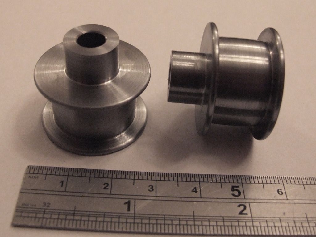
                              Still that meant workshop time. Having played with the maths and decided on a diameter of 0.85" for the governor pulleys, rather than the 1" as drawn, I updated my CAD model and generated a 2D drawing. Then I made them:

                              governor pulleys.jpg

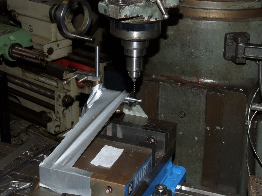
                              Final operation was to drill a 1.3mm hole through the pulley boss and shaft for a taper pin:

                              drilling governor pulley.jpg

                              Sticky tape are us!

                              The exercise tomorrow, once it starts to rain, will be to ream the holes for the 1/16" taper pins.

                              Andrew

                              Why do you always see a boo-boo in the post immediately after you've posted, but not before?

                              Edited By Andrew Johnston on 09/09/2017 20:49:07

                              #316188
                              Bazyle
                              Participant
                                @bazyle

                                Rain showers every 15 minutes it seemed so not too unhappy about being in the Men's Shed instead of painting my chimney. We only have half a wall left to line and with the insulation it is quite cosy. The end of the build phase is in sight. The only woman volunteer was happy to be outside filling screw holes and she brought an exceedingly good cake.

                                #316190
                                Muzzer
                                Participant
                                  @muzzer
                                  Posted by mark smith 20 on 09/09/2017 19:24:07:

                                  One question, what is the purpose of the 4 sloping holes…..

                                  Surely they are just the holes for the jaw fixing screws. Looks to me as if they have just been drilled right through, rather than being left blind?

                                  Murray

                                  #316192
                                  Muzzer
                                  Participant
                                    @muzzer
                                    Posted by Andrew Johnston on 09/09/2017 19:37:18:

                                    The refractometer looks almost identical to mine? I bought mine from Index Instruments in Ramsey.

                                    Yes, it's by Index too. I got mine from Broughton Lubricants at the same time as the oil. Saved messing about. I thought it may be a generic Chinese product but regardless of where it's made, Index seem to be a dominant supplier. They seem to do a refractometer for almost any appplication.

                                    Mine's calibrated for oil emulsion, 0-18%. My reading was about 7.5% after final messing about with buckets and oil, with the pump running it through to mix it up thoroughly.

                                    Murray

                                    #316204
                                    duncan webster 1
                                    Participant
                                      @duncanwebster1

                                      Today I went to the gala at the Kirlees Light Railway, a very good day out. If any of you are withinn range of God's county it's well worth a visit. The sound of a chime whistle echoing round the tunnel will stay with me for a while

                                      #316205
                                      Bob Rodgerson
                                      Participant
                                        @bobrodgerson97362

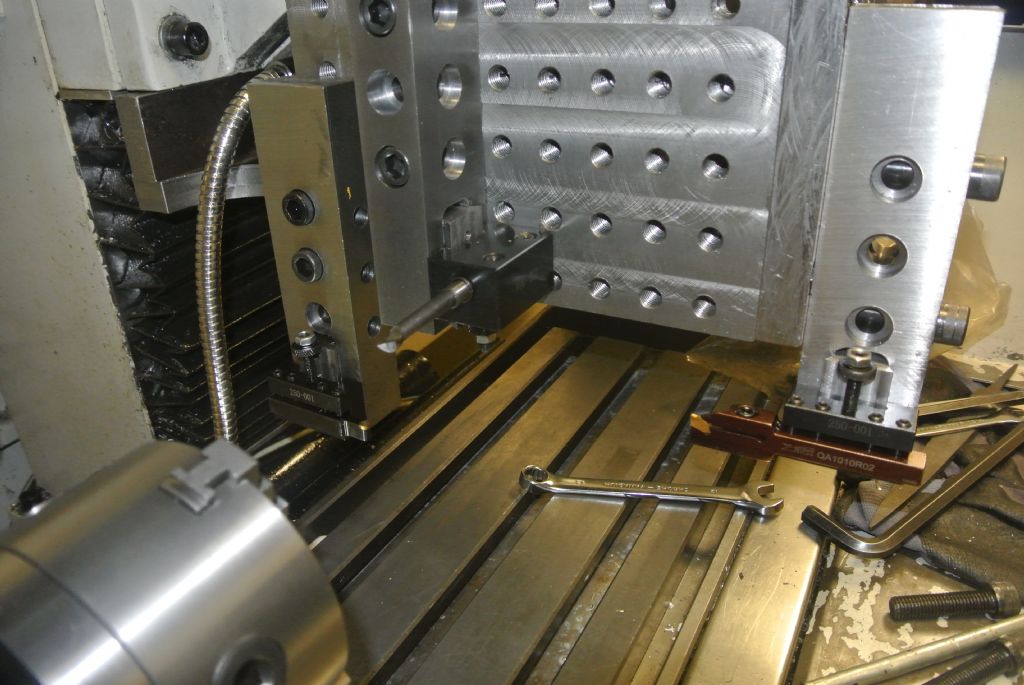
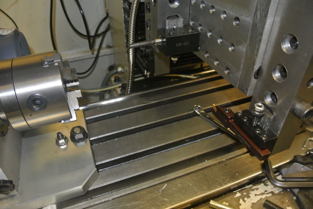
                                        I got round to fitting the Rapid Turn attachment to the milling table and set up my home made Gang tooling for it.

                                        I am pleased that so rigid but unfortunately the front plate is to far outboard of the spindle axis to allow use of the QCTP from the Lathe as I run out of Y his travel. However I will probably be able to set the lathe off centre on the mill table sufficient to permit it's use. I suppose that will teach me to double check everything and measure up properly.

                                        Here are some pictures with some as yet unfinished tool hangers attached.

                                        dsc_4322.jpg

                                        dsc_4323.jpg

                                        It is difficult to get a decent picture but at the foot of the tool hanger on the bottom left is a profile tool in the middle a boring tool and on the right a parting tool.

                                        There is more work to do on the hangers to accept parallel shank tooling such as drill chucks and ER 20 collets.

                                        #316207
                                        mark smith 20
                                        Participant
                                          @marksmith20
                                          Posted by Muzzer on 09/09/2017 21:50:34:

                                          Posted by mark smith 20 on 09/09/2017 19:24:07:

                                          One question, what is the purpose of the 4 sloping holes…..

                                          Surely they are just the holes for the jaw fixing screws. Looks to me as if they have just been drilled right through, rather than being left blind?

                                          Murray

                                          No they are seperate, i should have said the two behind the fixed jaw slope down and merge with the mounting bolts holes( the mounting bolt hole go straight through to the back. ).

                                          The two small diameter holes around 3 – 4mm behind the sliding jaw ,don`t slope but go straight through but emerge either side of the jaw bolt holes.

                                          There are also two identical holes on either side of the fixed jaw as well going right though to the jaw.

                                          So six holes in total which aren`t  threaded. (not including the 4 obvious  jaw bolt holes)


                                          Edited By mark smith 20 on 10/09/2017 00:24:11

                                          Edited By mark smith 20 on 10/09/2017 00:27:41

                                          Edited By mark smith 20 on 10/09/2017 00:28:09

                                          #316219
                                          Anonymous
                                            Posted by Muzzer on 09/09/2017 21:56:43:.

                                            Yes, it's by Index too.

                                            That would explain it; I've got the 18% FS one too.

                                            Andrew

                                            #316223
                                            Hopper
                                            Participant
                                              @hopper

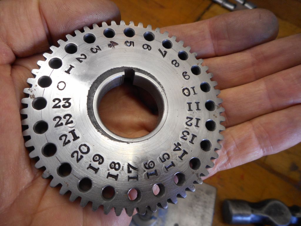
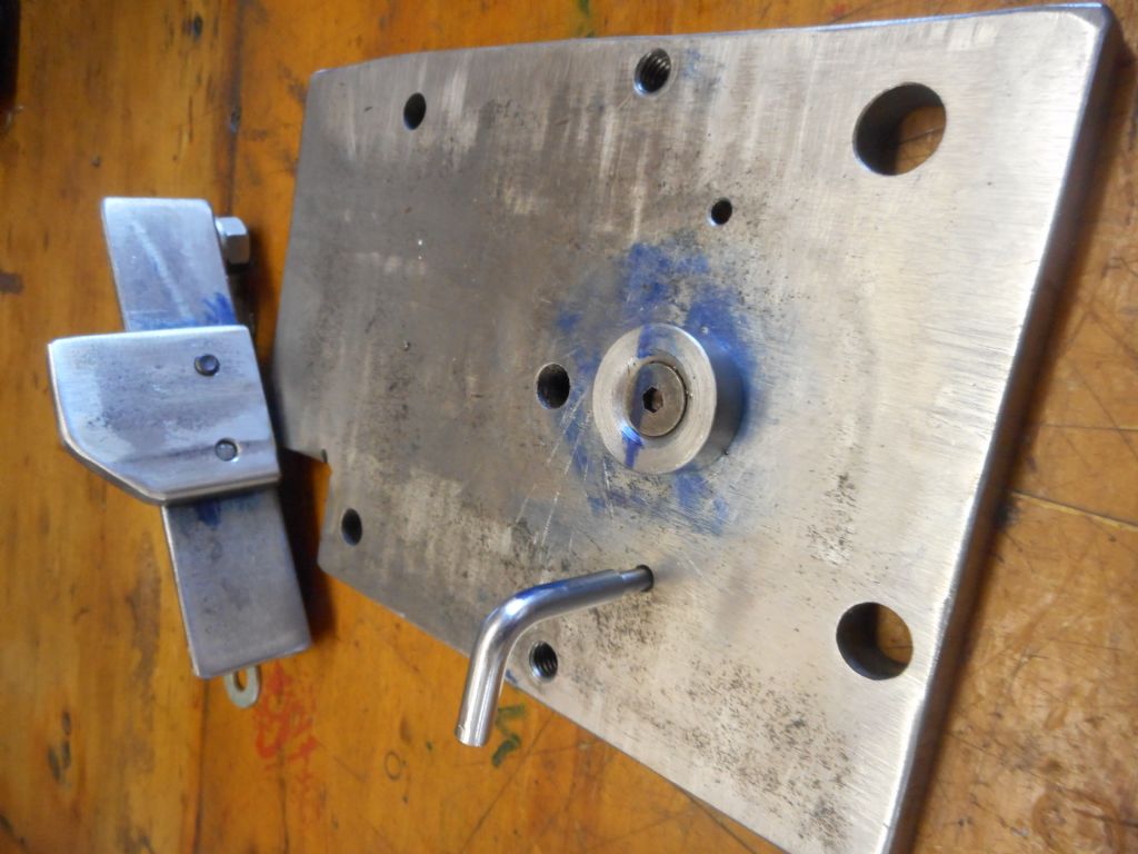
                                              Making progress on the fabricated versatile dividing head. After drilling the 814 holes in the three indexing plates, i was able to use one of them to drill the 24 holes in the main gear for direct indexing, and by spending the time to make a halfway decent stamping jig, got the numbers stamped on and looking very professional, if I say so myself.

                                              dscn3047.jpg

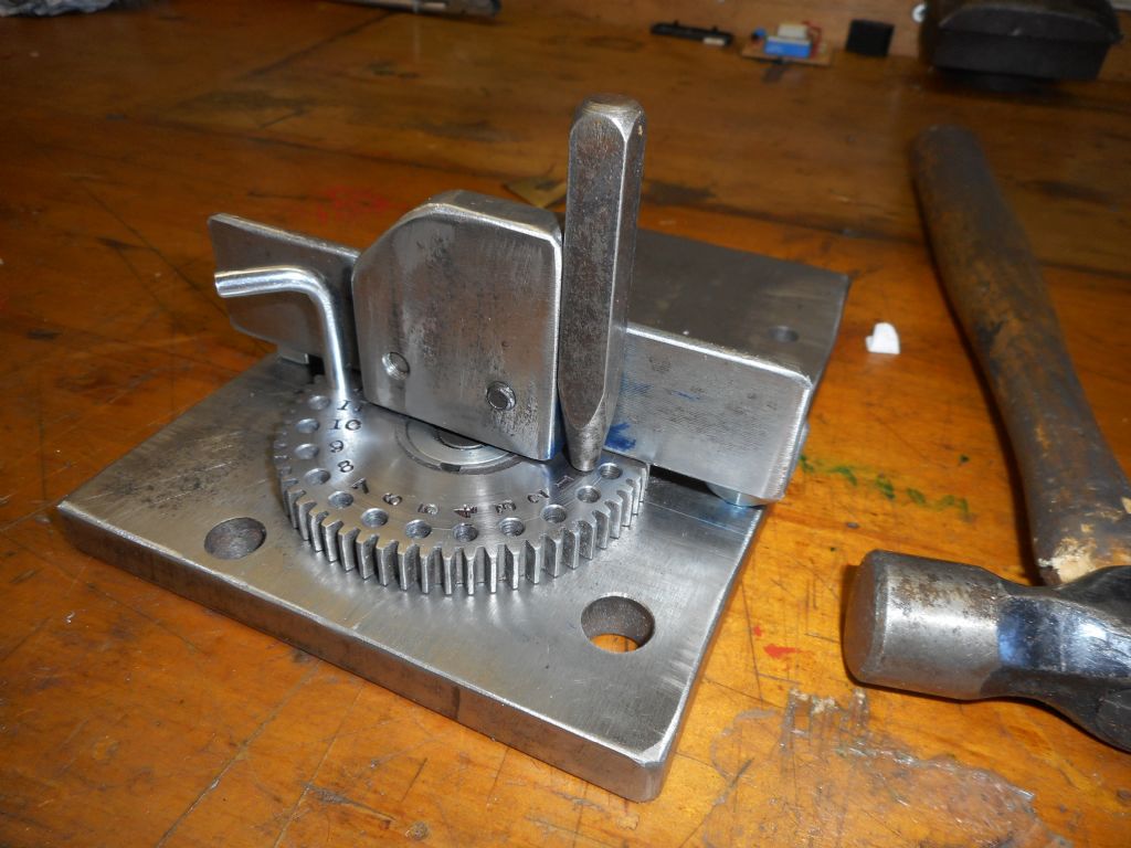
                                              The jig was an upgrade to the simple guide I made for stamping the index plate hole circle numbers, now with a hub added to mount the gear on, an indexing pin to engage with the holes in the gear and an indexing hole in the base plate, and a vertical guide for the number punch, so that numbers fall in straight lines and two digit numbers are correctly spaced. All made out of the scrap box.

                                              dscn3039.jpg

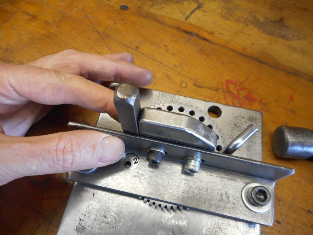
                                              The piece of angle iron is sat on a couple of 3/8 nuts for spacers and bolted down to the base, allowing the gear to be rotated beneath it with just the indexing pin removed.

                                              dscn3040.jpg

                                              View from the operating side showing the lateral adjustment on the vertical punch guide to accommodate double digits, via slotted holes for the two Allen bolts holding the guide. I went around full circle and stamped the first digits of each number, then adjusted position of the vertical guide and then went around and added the second digit to numbers 10 to 23. You can also see here the peephole I drilled so I could keep track of the last number I had stamped, just to double check I was stamping the correct new number each time.

                                              dscn3043.jpg


                                              Edited By Hopper on 10/09/2017 09:33:34

                                              #316238
                                              Anonymous

                                                Couldn't wait, so I've fitted the taper pins and finished off the end of the shaft:

                                                governor pulley pinned.jpg

                                                Coffee time now and then hit the garden for more weeding.

                                                Andrew

                                                #316333
                                                Michael Gilligan
                                                Participant
                                                  @michaelgilligan61133

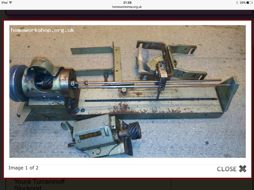
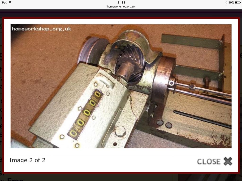
                                                  Yesterday; thanks to a kind gentleman advertising on 'homeworkshop' I acquired this:

                                                  img_1422.jpg

                                                  .

                                                  img_1423.jpg

                                                  .

                                                  We assume it to be the remnants of a Coil-Winding machine.

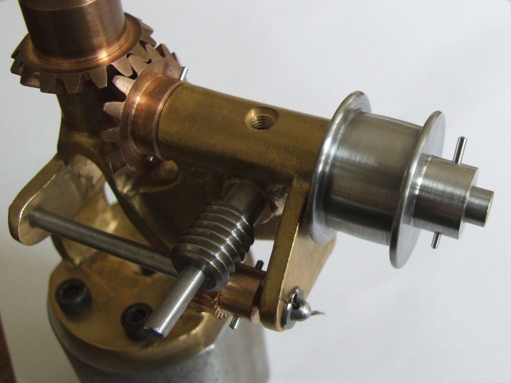
                                                  Today; I stripped it down for the bits I want [basically the headstock and the counter]

                                                  The build quality of the machine is horrendous, but those two items are good.

                                                  Question: Does anyone recognognise this assembly question

                                                  Clues: The machine came from France; the counter is by 'Zivy & Cie' of Paris; and the headstock casting is aluminium alloy with a steel front plate. … and the gears are very nice !!

                                                  Grateful for any thoughts.

                                                  MichaelG.

                                                  #316336
                                                  Muzzer
                                                  Participant
                                                    @muzzer

                                                    I've used a few coil winders in my time – I started out as a power electronics engineer, learning how to design and manufacture all manner of magnetic components and a coil winder was the machine of choice for flashing up parts, both prototype and medium volume production.

                                                    Must say, this doesn't look like a mainstream coil winder. It seems to lack critical parts like the wire tensioner and wire bobbin holder. And although there is a slotted bad, there's no tailstock or wire feeder. It's possible it was for making simple wound parts like cylindrical chokes but even so I'd expect the above parts to be present. Apart from the turn counter, it seems to be lacking most of the functions you'd need. I know a lot of parts are missing but I wonder if it is actually something simpler like a yarn or ribbon winder, possibly even for some sort of film?

                                                    Murray

                                                    #316346
                                                    Michael Gilligan
                                                    Participant
                                                      @michaelgilligan61133

                                                      Thank you for the thoughts, Murray

                                                      Frankly, it doesn't really matter what it was [although, of course, my innate curiosity makes me want to know]: What I'm more interested to know is what it was made from. … The 'machine' was obviously cobbled-together, and some of it is really quite nasty, but that 'headstock' must have been sourced from somewhere.

                                                      Thanks again

                                                      MichaelG.

                                                    Viewing 25 posts - 1,901 through 1,925 (of 2,518 total)
                                                    • Please log in to reply to this topic. Registering is free and easy using the links on the menu at the top of this page.

                                                    Advert

                                                    Latest Replies

                                                    Home Forums The Tea Room Topics

                                                    Viewing 25 topics - 1 through 25 (of 25 total)
                                                    Viewing 25 topics - 1 through 25 (of 25 total)

                                                    View full reply list.

                                                    Advert

                                                    Newsletter Sign-up