WARCO WM-250 lathe family and WM16 mill – 001

Advert

WARCO WM-250 lathe family and WM16 mill – 001

Home Forums Workshop Tools and Tooling WARCO WM-250 lathe family and WM16 mill – 001

  • This topic has 374 replies, 62 voices, and was last updated 6 July 2020 at 23:20 by Cabinet Enforcer.
Viewing 25 posts - 76 through 100 (of 375 total)
  • Author
    Posts
  • #122661
    mechman48
    Participant
      @mechman48

      Rik / all

      Fortunately I had bought an engine hoist to move my previous machine(Clarke C500 combi,before selling it) when converting my garage so managed to do most of it myself with the help of SWMBO.

      Another point to look out for on your machine, the change wheels are noisy, make sure that the backlash is set up as there seems to be plenty of slop on my gears radially & axialy so I suspect there will be some large clearances between the gear bores ID & the banjo pins/ shafts OD..anyone had similar probs / resolution?

      The way I've set up my backlash is to insert some folded paper (5 – 6 thou) in between the 40t spindle gear & Z2 gear as that seemed to be the worst,adjusted the banjo to nip the paper & tightened up, there was some improvement at that but had to leave off to attend to something else so will have to get back & check the other gear meshes later.

      Backlash adjustment.jpg

      George

      Edited By mechman48 on 19/06/2013 16:41:37

      Edited By mechman48 on 19/06/2013 16:43:01

      Advert
      #122669
      JasonB
      Moderator
        @jasonb

        Mine were noisy as supplied but I did the paper trick (only one layer) through the whole banjo and they are very quiet now, just do the same whenever I need to setup for screwcutting or revert back to the fine feed.

        Also watch the thin washers that space the gears off the banjo, get them wrong and two gears will rub sides and ring.

        Edited By JasonB on 19/06/2013 17:43:16

        #122674
        Rik Shaw
        Participant
          @rikshaw

          Thanks to Neil and Jason for that timely reminder. I was forgetting about the uses that a four way has over the Dixon type QCTP so I'll keep it.

          The bloke in the workshop at WARCO tells me that the QCTP is case hardened only, he mounts it in a four jaw and uses one of those cheap blue brazed tip boring bars to open it out. "Once you get under the skin it's like cheese" he said. I think I might try doing it on the mill with a boring head and tipped tool just to be different.

          Cleaned it down today and went to give it a test run – dead, lifeless, no power grrrrrrrr! Checked fuses, fuses OK. Call to WARCO. The bloke asked me if the change wheel cover was fitted correctly – no, it was on the floor. "The closed cover operates a micro switch" he tells me . Well I didn't know did I??

          Started it up but what a clatter! Removed cover again and disconnected the quadrant. Started up again, this time it was much quieter. I'm going to have to do something about those noisy change wheels. I have used the paper strips but it makes no difference. For now though, I have just cleaned all that nasty sandy, gritty grease from the gears and re-greased – still noisy though. Many years ago I worked at a place that had very large, old and noisy belt driven machinery with 3ft dia. spur wheels. After a while the gears got so noisy the maintenance fitters used to apply this stuff to the teeth, it came in sticks the size of a tube of silicon sealant. It worked like magic – I wonder what it was?

          I was just looking in the Axminster catalogue and spotted this paste called Ambersil Tufcut metal cutting compound. I was wondering if I might get away without using a coolant system if I used this stuff. Anyone tried it?

          Rik

          #123095
          mechman48
          Participant
            @mechman48

            Another mod I did on my 250V-F… the supplied chuck guard has only one small window which restricts viewing of the chuck to some extent.. for me… (As I'm a short a***e) or should I say my a***e is too close to the ground? , any way I cut out the top section & fitted a double, gapped, 2mm acetate panel in place, now I can see more of what's going on at chuck jaws, no doubt some will have removed the guard altogether.. personal choice! I considered this too but decided against it as it still catches cutting fluid instead of flinging it back at me, or on the floor, & I have a clear vinyl sheet at the back to stop any trailing up the wall, (you can just make it out in the background).

            250v-f mods  (1).jpg

            George.

            Edited By mechman48 on 25/06/2013 12:56:51

            #123549
            mechman48
            Participant
              @mechman48
              Posted by Mark P. on 09/06/2013 20:16:55:

              Just for the sake of interest what oil do you put in your WM250 gearbox?

              Mark P.

              Did a backlash check over on the rest of the changewheels as mentioned earlier & set the gap to a single paper sheet..3-4 thou' more improvement on the noise level, although still rattles somewhat,I am putting this down to the radial & axial 'slop' (not so much running clearances) on the ID of the gear bores & banjo shafts, as manufactured in china ,again, QC at point of manufacture.

              Checked oil levels in gearbox & saddle; both were lower than what is recommended so refering back to 'Grizzly' equivalent machine manual..BF20L who suggest ISO 60 grade oil, checked on Google for SAE equiv' .. SAE 20, so bought a litre of Engine oil SAE 15 – 40 & topped both up. Will use for a couple of weeks then drain off & replace all with new SAE 15 – 40 as no idea what the manufacturers put in originally!

              George.

              #123558
              Gone Away
              Participant
                @goneaway

                Posted by mechman48 on 01/07/2013 15:15:53:

                no idea what the manufacturers put in originally!

                Probably "oil". smiley

                #123561
                Rik Shaw
                Participant
                  @rikshaw

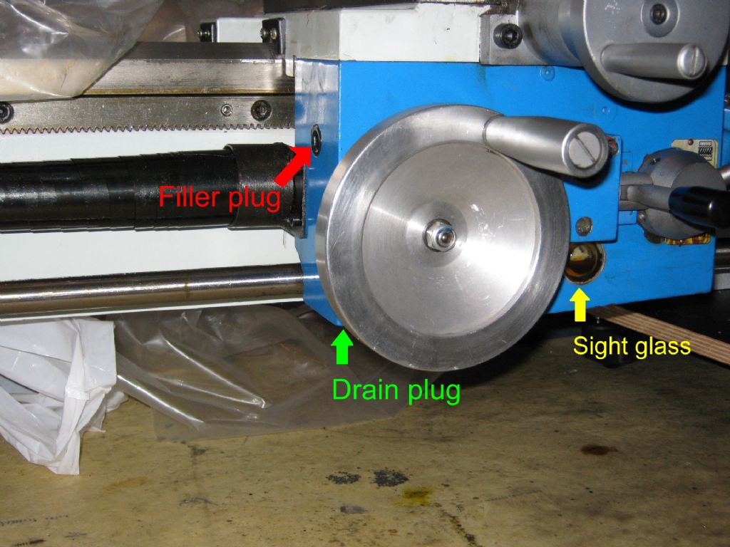
                  George – Grizzly manual gives instructions for "running in" a new lathe (which I have done). This is followed by their reccomendation to change the oil – which I have not done. But I will once I have figured out where the drain plugs are. Given the amount of foundry sand I have found everywhere I think their advice is sound. —— Rik PS thanks for the SAE 20 tip, I was wondering about ISO 60 which incidentally would not apply to me as ISO 66 teeth 2

                  #123638
                  mechman48
                  Participant
                    @mechman48

                    Rik /all

                    Have att. info for ref: Viscosity Classifications – Tribology-ABC . Look at table # 5 it gives the equivalent for ISO 46 – 68 = SAE 20.. which covers what we need hence why I put SAE 15 – 40 in for topping up, the equivalent in the gear oil range is shown as 75 – 80W so you could replace your oil with this on change out, Halfords (no connection) or similar shop generally have multi range gearbox oil,could be marked up as Hypoid / GTX 70 – 90W.. ? I'll probably go this route when I change mine.

                    Drain plugs:

                    Warco manual.. Lathe Gearbox Assembly page .. part # 11.

                    Lathe Apron Assembly page .. part # 27 looks to be the drain plug although this is described as 'screw' (usual excellent chinglish translation) check on your machine!

                    I'v looked up the Grizzly equivalent machine & as near as matters is the G0752.. pdf parts list page 84 .. gearbox..part # 814.. drain plug. It doesn't show where the apron drain plug is but logical deduction is that it would be underneath near the sight glass or low down on one of the ends of the apron casting.

                    PS, have just checked on mine & there is a SH screw underneath the autofeed (half nut ) lever which may well be the drain plug but looking at the Warco manual this is not identified other than showing as an unidentfied screw,with what looks like a ball bearing on top, nestled in between part #'s 28..'screw' & # 29 'Label'.. ? whatever the case it will be awkward to remove & refit. the alternative would be to remove the hex head sight glass(on mine) drain off from there & refill from the SH screw on the left side of the apron (3/4 way up casting) until clean oil comes out of the sight glass location,refit the glass & top up to 3/4 level. I can't see part # 27 'screw' unless it is flush & has been painted over when they have sprayed the casting (any other owners noted / resolved this point)..?

                    Cheers

                    George


                    Edited By mechman48 on 02/07/2013 11:01:54

                    Edited By mechman48 on 02/07/2013 11:04:55

                    #123673
                    Thor 🇳🇴
                    Participant
                      @thor

                      Hi George,

                      thanks for the link to the Viscosity Classification.

                      On my new lathe the drain plug is situated on the underside of the apron, at the left end closest to the headstock. I have a photo showing the apron.

                      hbm_290f_apron01s.jpg

                      Thor

                      Edited By Thor on 02/07/2013 18:21:39

                      Edited By Thor on 02/07/2013 18:22:25

                      #124298
                      john kennedy 1
                      Participant
                        @johnkennedy1

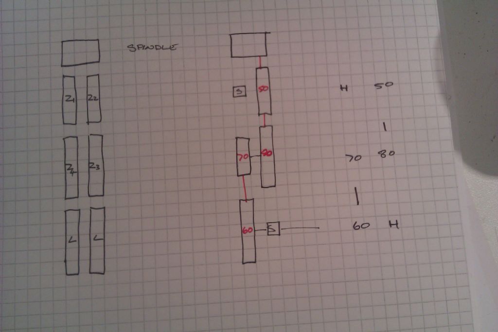
                        Hi everyone, I've had my WM250 lathe for about 3 1/2 years and up to now its served me well. I've come to stage where I need to cut a 12mm thread with a 1.75mm pitch. I've got to admit that I'm baffled by the thread table on the gear cover and also the manual. (which conflict on the gear sizes given) I can't work out what H & L mean (headstock & leadscrew perhaps?) Also it only shows 4 gears in the train, Z1 being represented by H, unlike 5 gears in the slow feed train. Also do the dotted lines in the manual or the small marks on the gear cover plate represent gears in mesh or gears on the same quadrant bolt??? Would someone please explain how I can arrive at the correct train. Thanks, John.

                        #124302
                        SteveW
                        Participant
                          @stevew54046

                          I'd be happier to calculate myself. Does anyone know what the leadscrew pitch (metric) is? And how many teeth on the headstock/spindle gear? I distrust tables (having been caught once) but perhaps that's just me!

                          SteveW

                          #124308
                          JasonB
                          Moderator
                            @jasonb

                            H means there is no gear, use a spacer either from when you remove the feed ratios or in the box with the change gears

                            L is the leadscrew gear

                            The vertical dash between mumbers show that the gear above meshes with the one below

                            Numbers side by side are on the same bolt eg Z1 & Z2 are on one stud, Z3 & Z4 on another

                            #124311
                            JasonB
                            Moderator
                              @jasonb

                              This may make it a bit clearer, gears based on the WM280 which may differ from the 250. to give 1.75mm pitch with metric leadscrew

                              Front selector in "A"

                              imag1762.jpg

                              Click to make it bigger.

                              Do check it first as I have found errors in the 280 chart relating to which position the front dial should be in but have only corrected teh imperial threads as I have a 8tpi leadscrew

                              Edited By JasonB on 11/07/2013 13:50:57

                              #124313
                              john kennedy 1
                              Participant
                                @johnkennedy1

                                Thanks Jason for taking the trouble to do a diagram.I can get my head round it now and try the gears shown in both tables. I'll do a test piece first and check with a gauge. By the way mine is a metric lathe with a 3mm leadscrew.

                                Steve, is there a formula to check I'll eventually have the correct gears? … John

                                #124382
                                mechman48
                                Participant
                                  @mechman48

                                  HI All,

                                  Help…. My WM16 vertical digital (Z axis) scale has just gone haywire; whatever amount I put on e.g..020" or .5mm doesn't register correctly comes up with something stupid like 6.250" , even 150.25mm. I have put new battery in, checked all fastenings are tight, zero'd everything but it's just throwing readings up of all description & reading flickers between stupid numbers even when I have managed to set a d.o.c. …sounds like the electronics have given up the ghost.

                                  I think it's still just in warranty, will check paperwork & contact Warco for replacement if so, but if not (or Warco's want to play silly buggers?) any owners have a solution ?

                                  George

                                  #124383
                                  JasonB
                                  Moderator
                                    @jasonb

                                    John, this is the formula based on my Imperial 280 but assuming its got a metric leadscrew, the head and gearbox should be the same on both its just the leadscrew that would be different.

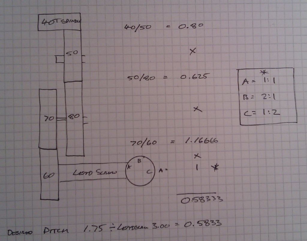
                                    We know the leadscrew will move the carrage 3mm per revolution of the chuck but we want it to only move by 1.75mm per rev so 1.75/3.00 = 0.583333

                                    Now to get the same number with the gears

                                    Basically divide the driver by the driven so the 40T spindle drives the 50T, 50T drives the 80T, 70T drives the 60T, this gives us the fractions 40/50, 50/80 & 70/60 noe expressed as decimals 0.8, 0.625 & 1.16666.

                                    The gearbox ratios are A=1:1, B=2:1 & C=1:2 which give the decimals 1, 2 & 0.5.

                                    You now multipy these decimals so 0.8 x 0.625 x 1.16666 x 1 = 0.583333

                                    If the two numbers are the same you have got it right. In our case they both come out at 0.583333


                                    imag1763.jpg

                                    Edited By JasonB on 12/07/2013 08:16:54

                                    #124384
                                    Rik Shaw
                                    Participant
                                      @rikshaw

                                      Keep us informed about your duff dro on your mill George.

                                      On the subject of DRO,s, as far as I can make out there are two types of DRO available from WARCO (and others) for these machines. One type seems to be a simple strip with an integral readout and the other appears to be some sort of expensive glass scale used in conjunction with a separate larger display.

                                      If the above is correct, how are both types of scale affixed to the machine?

                                      Rik

                                      #124387
                                      SteveW
                                      Participant
                                        @stevew54046

                                        John, I think Jason has done well to explain what has to be done. It seems much more complicated in metric – again I think that's just me… I think of it as 'how many times slower do you want the leadscrew to go compared to its existing pitch/tpi'. If the leadscrew was the same speed as the spindle you would cut the same pitch thread as the leadscrew.

                                        SteveW

                                        #124392
                                        JasonB
                                        Moderator
                                          @jasonb

                                          Rik its just a case of drilling and tapping some holes on the machine where ever suits. The glass scales are far less temprimental than the calliper type scales plus you get all the functions of the display head.

                                          J

                                          #124394
                                          john kennedy 1
                                          Participant
                                            @johnkennedy1

                                            Thanks again Jason,you make it look so easy. I got it set up last night 30-80 70-60 but didn't have time to do the test piece. Will update. John

                                            #124395
                                            Ady1
                                            Participant
                                              @ady1

                                              its just a case of drilling and tapping some holes on the machine where ever suits.

                                              If anyone is wondering about this because they haven't done it before, cast iron drills and taps extremely easily

                                              If your hss drill struggles for whatever reason those small carbide tipped masonry drills sail through cast iron and can be used to make a pilot hole

                                              #124397
                                              Anonymous
                                                Posted by SteveW on 12/07/2013 09:15:26:

                                                It seems much more complicated in metric – again I think that's just me…

                                                No, it's not just you, the maths is more complicated. If you look at a thread dial indicator for an imperial lathe there's normally just a single 'gear' to engage with the leadscrew. On a metric lathe the thread dial indicator will have a stack of 'gears' which have to be selected depending on the thread pitch.

                                                Regards,

                                                Andrew

                                                #124398
                                                mechman48
                                                Participant
                                                  @mechman48

                                                  Rik

                                                  My DRO's are magnetic strips with remote linked readouts via cable, purchased from another supplier but very similar to Warco's. They come supplied with fixing brackets, the read head bracket can be modified to suit the machine but I made a new bracket to suit, not difficult to fit.

                                                  George

                                                  ps. just remember to keep the bar level

                                                  Edited By mechman48 on 12/07/2013 11:21:14

                                                  #124483
                                                  john kennedy 1
                                                  Participant
                                                    @johnkennedy1

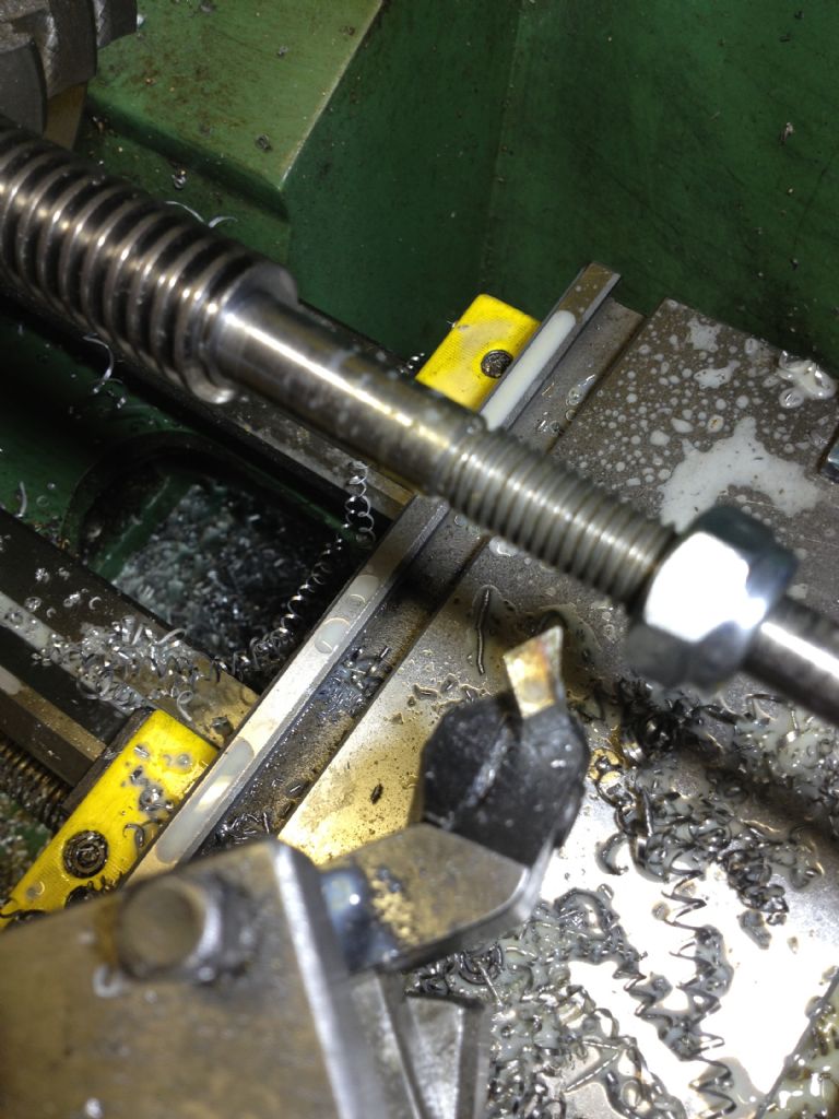
                                                    Just an update, due to your help I managed to cut the thread on my wm250. The nut fits very well with no shake. Set the topslide over to the 60 deg mark and fed that in 1.2mm. Its for the retaining nut on a new leadscrew I'm fitting to my Harrison milling machine. You'll notice I'm using a Diamond tool holder that comes with a jig to grind the tool to 6o deg. Thought it was a bit of a gimmick at first but if you set the jig screw at the correct angle (trial and error) it comes out great. Thanks again for your help. John

                                                    060.jpg

                                                    #124551
                                                    Rik Shaw
                                                    Participant
                                                      @rikshaw

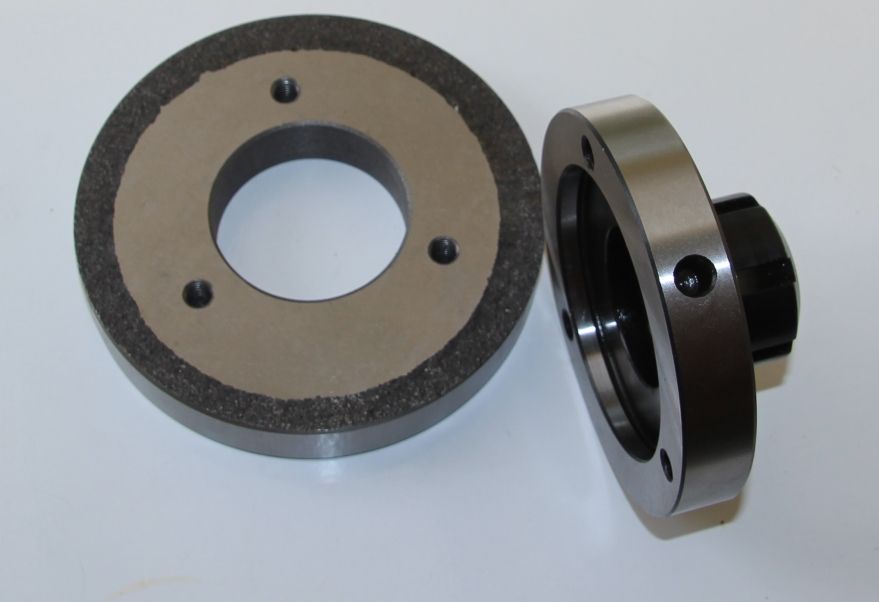
                                                      I ordered a new collet chuck with my lathe and would have used it this afternoon but discovered that the backplate that came with it needs to have a locating boss machined on it to take the chuck. Although the chuck has three tapped holes I was contemplating opening them up to clearance and drill and tap the backplate but then realised that the backplate has been hardened – so drilling is probably out.

                                                      Is it normal for WARCO to expect the customer to do the machining? Maybe the job is a better one done on the customers own machine – I don't know.

                                                      The backplate shown is "as delivered".

                                                      Rik

                                                      collet chuck.jpg

                                                    Viewing 25 posts - 76 through 100 (of 375 total)
                                                    • Please log in to reply to this topic. Registering is free and easy using the links on the menu at the top of this page.

                                                    Advert

                                                    Latest Replies

                                                    Viewing 25 topics - 1 through 25 (of 25 total)
                                                    Viewing 25 topics - 1 through 25 (of 25 total)

                                                    View full reply list.

                                                    Advert

                                                    Newsletter Sign-up