Vintage lathe cross slide adjustment

Advert

Vintage lathe cross slide adjustment

Home Forums Manual machine tools Vintage lathe cross slide adjustment

Viewing 25 posts - 1 through 25 (of 37 total)
  • Author
    Posts
  • #515709
    Arthur Moore
    Participant
      @arthurmoore87122

      Hello everyone,

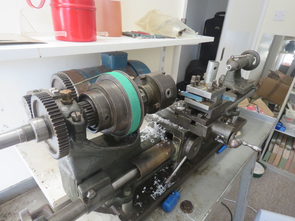
      I have a very ancient lathe which I bought at a model railway show for £10 and just had to add a motor and drive pulley.

      lathe overall head end.jpg

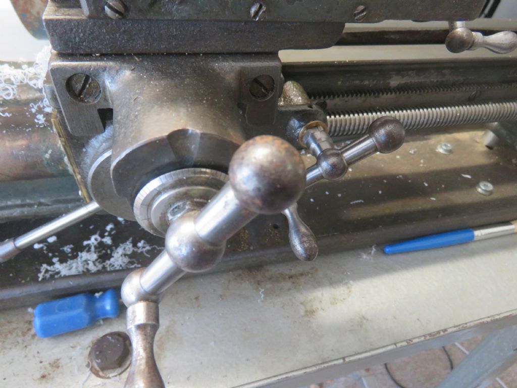
      It seems to be working well, but there is an enormous amount of play in the Y feed – approx 1.4mm.

      lathe y feed.jpg

      Does anyone know how to take out at least some of this slack? I guessed I need to hold the nut and that would enable me to unwind the handle. Then either tighten the nut, or add washers as shims and refit the handle. Is that correct?

      If so I have another problem. The nut is about 2.3mm thick and 11.4mm across flats (29/64"?) – so what spanner would fit and where do you buy a spanner that thin? Nothing thicker will go in the gap between the handle and the cross slide.

      The X feed has almost no slack and feels comfortable to use, but does not have an indicator wheel

      lathe x feed.jpg

      Can you buy these wheels? It seems to be 16 turns of the handle to the inch, so 0.0625 per turn.

      I guess fitting would be similar to what I have to do on the Y feed?

      N.B. I am managing with the lathe as is, provided I always feeding from the same direction, which I believe you should do anyway. But I have to keep on stopping the lathe to measure diameters and then feed back in. There then seems to be the risk of an error of up to 0.2mm.

      Thanks for any help and suggestions

      Arthur (beginner)

      Advert
      #14119
      Arthur Moore
      Participant
        @arthurmoore87122
        #515715
        Roger Best
        Participant
          @rogerbest89007

          A lot of questions but its still a bargain.

          You probably have a worn lead screw nut, so it will need some stripping to tell.

          What speed is your motor, these old dears don't have the bearings for high speed?

          #515717
          Jeff Dayman
          Participant
            @jeffdayman43397

            Hi Arthur,

            You will probably find the nut is badly worn in the cross slide. You can either make a new one or slit the old one and add a screw to make the nut sort of "pinch" the thread to reduce the backlash. However you may find the screw is also worn. New screw can be made or the old one chased (threads made thinner, removing material just enough to take the thread to a uniform state same size as worn part) and a new nut made.

            For a spanner I suggest finding a bit of gauge plate (oil hardening tool steel, ground flat both sides, sold by tool suppliers) and hacksawing / filing out the opening to fit the nut, to make a spanner. It may work fine without hardening if you leave enough "meat" beside the opening. 10" or 250 mm long would probably be fine. Wrap the end in electrical tape for good grip and to protect your hands.

            You could also buy a thicker spanner (maybe 12 mm ) at a pound shop or cheap imported tool dealer and grind the sides to fit.

            #515719
            Ady1
            Participant
              @ady1

              For thin spanners you buy the cheap rubbish sets, they can be pretty useful

              The handle is probably attached to the shaft with a tapered pin

              Once you know what make and model you have it's easier to hunt for info, I don't recognise it but someone in here will know

              #515724
              Arthur Moore
              Participant
                @arthurmoore87122

                Hello again.

                The motor is 950rpm with equal speed on the lathe, or 1.6 step up or step down.

                There seems to be no identifying marks on the lathe, so I do not know what make or model. I read there were quite a few generic machines made, especially during WW2, so maybe it is one of those?

                To remove the cross slide in order to access the cross slide nut do I just keep unscrewing the lead screw until I can pull it apart?

                Thanks, Arthur

                #515726
                old mart
                Participant
                  @oldmart

                  Remove the two screws in your second picture and you can unscrew the leadscrew. The cross slide will probably slide off. If it stops, then you will have to remove the compound with the toolpost and look for screws holding the cross slide nut and remove them.

                  #515727
                  ega
                  Participant
                    @ega

                    Two sources of thin spanners to use for this kind of thing, or modify for such use, are the old Terrys tappet spanners or those sold for adjusting cycle hub cones, etc

                    #515730
                    Dave Halford
                    Participant
                      @davehalford22513

                      That's got 6 speeds as it looks to have a back gear.

                      As Ady says the handle is normally held on with a pin.

                      old pushbike spanners are another source of thin tools

                      #515736
                      Clive Foster
                      Participant
                        @clivefoster55965

                        Sounds like you are running the lathe much too fast.

                        Typical countershaft speeds for machines of that era would be in the region of 250 to 350 rpm. Generally the spindle oiling arrangements for these simple plain bearing headstock machines aren't up to handling speeds above 600 rpm.

                        Concerning identification the inverted rack with teeth pointing upwards provided for driving the saddle is very unusual. Coupled with the extremely skimpy saddle apron and left hand operated half nut lever for screw cutting it ought to be possible to identify it. I'm fairly sure that a machine with similar features was added to the list at **LINK** sometime in the last 4 or 5 years. I have a horrible suspicion that machine had its feednut cut directly in the saddle casting. If so it will need to be bored out and new nut fitted. Which may be difficult as space will be limited.

                        I'd undo the two screws holding the handle assembly to the cross slide then wind the screw out so you can see whats going on and, hopefully discern how it's all put together. On a machine like that expect some creative simplicity to minimise the number of parts. With the screw assembly removed pull off the cross slide too so everything can be examined and given a proper clean.

                        Clive

                        #515743
                        Bazyle
                        Participant
                          @bazyle

                          It looks like one of the RandA type which were made by and for a number of companies.

                          Backlash isn't a problem until the nut fails to hold and skips a 'tooth'. Learn to tlive with it for the moment until you get to know more about lathes otherwise you'll get bogged down in a repair cycle and not make anything for months,
                          A more pressing problem is a countershapft to bring th espeed down, but you can make wooden pulleys and run a shaft in plummer blocks on a wooden frame.

                          #515757
                          Clive Brown 1
                          Participant
                            @clivebrown1

                            11.3-11.4mm a/f is 3/16" Whit. or 1/4" BSF spanner size. The nut won't be too tightly done up. A piece of 3mm mild steel flat, a hacksaw and a file wil soon produce a spanner.

                            #515815
                            Nicholas Farr
                            Participant
                              @nicholasfarr14254

                              Hi Arthur, I agree with Bazyle that it looks very much like the RandA designs or the variants RandA lathes If it is slack between the cross slide and the screw you feel you need to adjust, you will see a noticeable gap between the nut and the cross slide when you wind the handle one way or the other. If there is no noticeable gap, it is likely that the thread that the screw, screws into is worn, which may be an extra problem for you, as with most of these types of models, they have the screw thread cut into the saddle casting and there isn't much metal to bush and re-tap a new thread, the photo below shows a RandA one that I have, to show you what I mean.

                              screw.jpg

                              Yes, if you continue to wind the cross slide out, it should most likely come off the saddle when the screw comes to the end.

                              Regards Nick.

                              Edited By Nicholas Farr on 28/12/2020 09:29:46

                              #515821
                              Mike Hurley
                              Participant
                                @mikehurley60381

                                If you need to remove the handle(s) they are usually held in situ on these older machines with a taper pin. These can be a bit of a sod to get out if they have been fitted flush both ends, and will have corroded a little so won't come out without a fight. Carefully clean off any grot and polish the handles boss, then use a magnifier and you should just be able to detect which is the 'thick' end and which the 'thin'. Get / make a proper sized drift sized for the 'thin' end, support the other side of the boss and tap away.

                                Dont go too heavy, a little heat may help. If you're too enthusuatic you will sort of 'rivet' over the thin end and it will be almost impossible to get out without drilling.

                                £10 for a lathe like that Arthur? You're obviously like one of those Lucky people I see on the Antiques roadshow on tv who buys a piece of costume jewellery from a charity shop for 50p and it turns out to be Faberege worth £1000's! If I spent 50p like that I'd usually find out that it was only worth 20p! Happy turning!

                                Edited By Mike Hurley on 28/12/2020 09:59:57

                                #515847
                                Arthur Moore
                                Participant
                                  @arthurmoore87122

                                  Thanks for all your helpful replies. It is good to know which machine I have. It looks as if someone has fitted a new handle to replace the screw cutting gears.

                                  I think Nick has accurately described the problem <<If it is slack between the cross slide and the screw you feel you need to adjust, you will see a noticeable gap between the nut and the cross slide when you wind the handle one way or the other.>>

                                  So hopefully not the more serious problem of the saddle casting being worn.

                                  I shall either find or make a spanner of the correct size and see what happens if I turn the nut. If that does not help I will probably take Bazyle's advice and leave well alone.

                                  Mike – thanks for your kind comments. I shall know not to bin the lathe if Father Christmas brings me a nice new one! (Only joking – but it is nice to know that these old tools are appreciated). I am lucky enough to have a BCA miller similarly acquired from a friend who just wanted rid of it to make room on his bench.

                                  I really need as high a speed as possible for making very small parts, such as top hat bushes 4mm across in brass or plastic . I am currently running on the lowest main drive setting (600rpm) and obviously only take small cuts. I tried with the back gear and the cut was really rough at such low angular velocity. I only use the lathe intermittently as I keep checking diameters, so do not think I can reduce the speed further, but your comments were very helpful. I shall know not to use her at 1500rpm!

                                  Arthur

                                  #515880
                                  Howard Lewis
                                  Participant
                                    @howardlewis46836

                                    For a machine of that vintage, the nuts are very likely to need Whitworth or BSF spanners, not Metric or A/F..

                                    The threads wiil probably be BSW or BSF, with possibly BA for things like gib adjusters.

                                    You need to distinguish between slack and backlash

                                    Backlash is wear between leadscrew and nut, and unless there is provision for reducing backlash, such as split nut, short of making new parts, there is not much that you can do about it. You just learn to take out the backlash as you use the machine. (If you overshoot, back off by more, at least twice, than the backlash and then advance to where you want to be )

                                    If there is play between the handle and the cross slide, if possible the handle can be moved along the Leadscrew to close the gap. If the position of the handle is fixed, by a pin, the space can be filled with one or more washers, or even better, a custom made spacer. Which you can make on the lathe!

                                    For this lathe, if Imperal, as it seems to be with a 16 tpi leadscrew, you need to work in inches and thous, to make life as simple as possible. Try putting on a cut of 0.02 mm using a dial with 125 graduations, let alone 62.5!.

                                    If you want graduated dials, you will have to add them. (Whjch means making, or finding some kind soul in your Model Engineering Club who will make and fit them for you) You certainly won't find any "off the shelf".

                                    A dial for a 16 tp[i leadscrew will need 62.5 graduations to give 0.001" increments. "And a Half"?

                                    Yes! I made one for my Adept Shaper. It looks a bit odd with 62 evenly spaced marks and then a half size gap, but that is what it takes, unless half thou graduations turn you on. For those you would need a larger diameter dial to accommodate the 133 marks with a sensible spacing. The wider the spacing, for a thou, the more accurately you can estimate lesser parts.

                                    Probably essential on a machine with plenty of backlash.

                                    Howard

                                    .

                                    #515942
                                    Arthur Moore
                                    Participant
                                      @arthurmoore87122

                                      Success!! I found an unmarked spanner deep in a box in the garage and that fitted the nut. I held the nut and the handle just unscrewed. A wrench on the shaft held that still while I tightened up the nut to take up the slack, without making it too tight, then I held the nut to re-tighten the handle.

                                      It is now sweet to use with a sensible amount of free movement, but the handle doesn’t flop around any more.

                                      Now all I need to do is to get to grips with thou, when all my drawings are in mm.

                                      I am currently doing some data inputting of accident reports for the National Railway Museum and that has a column in £-s-d and that is nearly as bad to remember – next year is fifty years since it was phased out!

                                      Thanks again for all your help

                                      Arthur

                                      #515947
                                      Howard Lewis
                                      Participant
                                        @howardlewis46836

                                        Set your calculator to divide by 25.4, or better still set up a spreadsheet to calculate all the dimensions for you.

                                        Bet that the dimensions will be whole mm, leading to some strange Imperial decimals, unless they have already been translated from the original Imperial to a Metric (possibly the nearest ) dimension.

                                        Good luck

                                        Howard

                                        #515954
                                        Arthur Moore
                                        Participant
                                          @arthurmoore87122

                                          Hi Howard,

                                          I think I will pin a crib sheet over the lathe with mm and a separate 0.1mm column as I usually get somewhere near, measure and then take off the last few thou with rather more care.

                                          Arthur

                                          #515957
                                          Howard Lewis
                                          Participant
                                            @howardlewis46836

                                            The problem that I envisage is that the original drawings were possibly done in 1/64. Someone converted 64s to nice decimal dimensions.

                                            Then along came someone else who calculated the Metric sizes and probably rounded them up or down to nice round numbers.

                                            End result is likely to be 1/2" becoming 12.7 mm "so lets call it 13 mm". If you are lucky. 3/8" became 9.5 mm

                                            End result something which which is even further away from being a true scale model to become something which may begin to look a little odd and out of scale.

                                            That might even be a benefit. But you may not know until the model is well on the way to completion

                                            Shades of "Send reinforcements, the battalion is going to advance" becoming "Send three and fourpence, the battalion's going a dance"

                                            Meccano Ltd used to make Dinky Toys from actual manufacturer's drawings, but with slight modifications to keep the model looking true to scale! They didn't always succeed.

                                            Howard

                                            #515970
                                            Arthur Moore
                                            Participant
                                              @arthurmoore87122

                                              Hi Howard,

                                              Although I used to do 5" live steam I lived abroad for a while with no workshop and now I am back in the UK I model in 7mm / ft (which has always seemed to me a particularly weird scale).

                                              I use a mix of scale drawings (which may not be accurate), scaling from works drawings where available and photos, which show things like rivet details and class variations not apparent from the drawings. I also think you have to try to make it look right – which beading actually shows, what disappears in the paintwork.

                                              At least when they are my own drawings any errors are my fault, but in these small scales you also have to make allowances for issues such as back to back being wrong and material thicknesses and clearances which have to work. Still it all keeps my mind active.

                                              Arthur

                                              #515973
                                              Howard Lewis
                                              Participant
                                                @howardlewis46836

                                                Hi Arthur,

                                                If you make your own drawings then you are master of your own fate.

                                                You are spared the inconsistencies that arrive after several people have applied their brains, slide rules and calculators to a machine.

                                                The tables at the front of Zeus charts take some of the pain out of changing measuring systems

                                                Otherwise, as you say a "crib sheet" containing the relevant dimensions and their equivalents is a must have.

                                                Now that you have removed the "slop" from the lathe you are all set to go!

                                                May your cuts be clean and the right size

                                                Howard

                                                PS Have you tried a Tangential Tool for turning and facing? Easy to sharpen, only one face to grind.

                                                #515980
                                                Arthur Moore
                                                Participant
                                                  @arthurmoore87122

                                                  Hello Howard,

                                                  No – I have not tried the Tangential Tool. How do you find they cut compared to conventional lathe tools?

                                                  #515982
                                                  Georgineer
                                                  Participant
                                                    @georgineer
                                                    Posted by Arthur Moore on 28/12/2020 18:10:24:

                                                    … I model in 7mm / ft (which has always seemed to me a particularly weird scale)….

                                                    My favourite scale is one I came across recently when reading a 1920 book describing how to design an electric tramway:

                                                    "… use squared paper divided in millimetres. On this, taking as a convenient scale 1 centimetre to a furlong, the line is marked off…"

                                                    By the way, I find a useful rule-of thumb for conversion is to say that 1 mm = 40 thou. It's really 39.6, but 40 is close enough for roughing out and I find it easy to visualise.

                                                    George B.

                                                    #516083
                                                    Arthur Moore
                                                    Participant
                                                      @arthurmoore87122

                                                      George – that is lovely!

                                                    Viewing 25 posts - 1 through 25 (of 37 total)
                                                    • Please log in to reply to this topic. Registering is free and easy using the links on the menu at the top of this page.

                                                    Advert

                                                    Latest Replies

                                                    Home Forums Manual machine tools Topics

                                                    Viewing 25 topics - 1 through 25 (of 25 total)
                                                    Viewing 25 topics - 1 through 25 (of 25 total)

                                                    View full reply list.

                                                    Advert

                                                    Newsletter Sign-up