Tom Senior Light Vertical Milling Machine

Advert

Tom Senior Light Vertical Milling Machine

Home Forums Workshop Tools and Tooling Tom Senior Light Vertical Milling Machine

Viewing 25 posts - 101 through 125 (of 129 total)
  • Author
    Posts
  • #261980
    Michael Gilligan
    Participant
      @michaelgilligan61133

      Thanks for the extra photos and description, Rod

      In my 'umble opinion, you have identified a design defect crying 2

      I am perfectly happy that the three co-planar pads are intended to be locked-down tight [after lateral adjustment], but I would have hoped to see some sort of 'detailing' to provide a seperate locking mechanism.

      Sorry, I won't be able to post any photos today, but I will try to take some over the next few days.

      MichaelG.

      .

      P.S. … I've just found this [SouthBend] document from US Army, which might be of interest; the machines are not wildly dissimilar. http://www.lathetalk.com/library/sbarmy7shaper.pdf

      Edited By Michael Gilligan on 20/10/2016 09:46:12

      Advert
      #261982
      Tendor
      Participant
        @tendor

        Very much appreciated thanks Michael. I agree that it appears some modification/addition is likely needed.

        Any examples of 'good' lock designs for these 'solid'-type gibs would be of interest and appreciated.

        Rod.

        #262004
        Mike E.
        Participant
          @mikee-85511
          Posted by damian noble on 14/10/2016 12:49:30:

          Hi all

          Been a while since I updated the thread as I've had a few other things get in the way of finishing up.

          I've finally got the mill back together and with a new name plate its ready for wiring up which will be the job for this weekend.

          20161014_123724.jpg

          Hi Damian, First, let me say that Dorothy & I enjoyed meeting you at the Star Party in Brecon. The mill looks great !, and so does that large mirror support behind it. Did the adjustable feet come with the machine (mine are missing) or did you have to acquire them separately ?

          #262114
          John Clayton 2
          Participant
            @johnclayton2

            Lovely job smiley

            How did the rewire go?

            #262306
            Michael Gilligan
            Participant
              @michaelgilligan61133

              Posted by Rodney Entwistle on 20/10/2016 09:36:40:

              … I agree that it appears some modification/addition is likely needed.

              Any examples of 'good' lock designs for these 'solid'-type gibs would be of interest …

              .

              Rod,

              To avoid cluttering Damian's thread; I have started a new one: Locking Devices

              http://www.model-engineer.co.uk/forums/postings.asp?th=121574&p=1

              Hopefully, others will contibute some interesting alternative designs, and you will find something that suits your purpose.

              MichaelG.

              #262908
              Blake Mackinnon
              Participant
                @blakemackinnon33134

                Hello Alan … as a possessor of a Tom Senior M1 who was aiming to sell the machine (clearly the action of a yahoo) – I attempted to give heads up to the yahoo group only to find one needed to join to post such a message. Attempted – but refused. I suppose one, by intimating sale of the necessary to belong, debars oneself. Auto debarring seems my forte… The idea was that as I'm contemplating a move and all that entails, perhaps I could get something smaller. Anyway – smarting from the 'blow', I re-assessed and concluded there was nothing as versatile and/or I wanted, could afford or might have space/muscles for – – partly as a result of having seen your Dore Westbury tweak. In fact I did the same some years ago – but nowhere near as skillfully. 'Self assessment' – could have done better! So the upshot of the above is the resolve (as now retired) to renovate said M1 and vertical head – and not sell.

                The above images and tales of similar exploits are very useful and inspiring (as is the Stepper-Head Lathe – I bought the Compucut driver many years ago to make something similar as a means to cut complex decoration on ceramic items which were then fired. Now playing with this as a 'CNC version' of the Holtzapffel – bit mind boggling – just in process of cutting pattern on a six inch red clay sphere using two rotary axes. hmmm)

                One thing puzzling me on your Dore Westbury conversion is that there seems no motor to drive the horizontal axis. In my attempt to achieve the same whilst still driving the horizontal axis (i.e. keeping power feed) it was something of a squeeze to fit the mounting block for the vertical head and the motor drive to horizontal spindle – park the overhead bar etc (have you re-configured/shortened the rear hinged cover?). Often my solutions are driven by time, what is available in 'the heap' and need to arrive at working solutions so as to remain productive. Retirement has altered those constraints to a degree. I used some 240v DC servo motors to drive both vertical and horizontal heads having also the drives to hand. The caddisfly larva operates on similar principles i.e. stick together what is available.

                I noted on one post somewhere that a renovator of a Tom S M1 tigged up non-standard holes in the coolant tray – a laudable approach to 'originality' – a standard I would find hard to follow as I was wondering whether one could house the drive motor in the base – such action presumably needing new cutouts for the drive belt etc. (A drawer would be handy too)

                ANYWAY -Is that what you did in your nice Tom Senior rework re- drive motor for horizontal?

                Grateful for any info on that issue.

                Blake

                #262914
                Alan Jackson
                Participant
                  @alanjackson47790

                  Hi Blake,

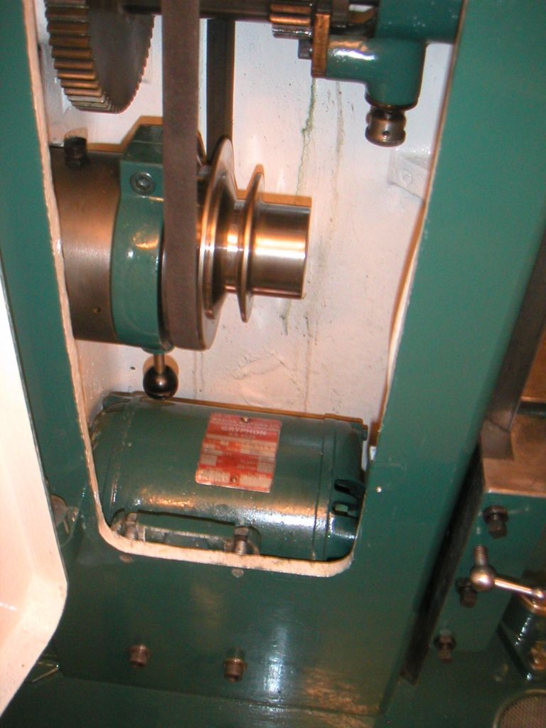
                  I hope this is not classed as an interference on this thread, but since you ask. I put the original motor inside the column. I cut an oval hole in the back of the column for the motor spindle and brought a new shorter vee belt. It works great, I have run it for long periods and it only gets slightly warm. This then frees up the top surface for the Dore Westbury head You can see more photos in my photos.

                  Alan

                  original top mounted motor shoehorned inside column.jpg

                  #262939
                  Blake Mackinnon
                  Participant
                    @blakemackinnon33134

                    Hi Alan … interference might arise from my 'crossed threads' – but as they are all on the topic of TS related renovation/improvement projects I think my pitch a partial fit – and your response greatly appreciated. Damien – sorry if my post in your thread was impertinent/naughty or off piste so far as protocol goes – am a bit of a newbie at this so learning. Would it be more appropriate to start another thread? BTW lovely looking result on the Light vertical Mill. A standard to aim at! Great images.

                    Alan… that's another squeeze – and you cutting an oval hole makes me feel somewhat less guilty in contemplating similar 'non standard' major surgery. In accommodating the 2.25''dia. overarm bar by sliding fully back over the top of the belt guard did you alter/shorten that guard or import one off a LVM? In its present guise on mine I bought and fitted a shorter bar (still have the longer) that is 'out the way' of the vertical head and just touches the inside of the rear cover when parked.

                    When I said in the base – I should have said in the stand. Damien's excellent images lead me to wonder whether there is just enough room below the coolant 'tank' – but either possible housing, as opposed to atop the column, seems to need cuts/holes – + careful thought.

                    Am thinking of getting the table reground as there are some slight dings/gouges … There's a good grinding firm near me north of Ludlow – I hope this should be straightforward.

                    Thanks for all the very helpful info/inspiration/insights…

                    Blake

                    #263328
                    damian
                    Participant
                      @damiannoble34800

                      Hi all

                      Firstly apologies to everyone for my lack of input here for some weeks the thread has developed quiye a bit of interest in the meantime.
                      I have been rather busy and the mill is wired up and in use. I shall post pictures of the full wiring when I get chance and answer the questions especially the one on the gib strip as I had the same question myself so will learn something along tge way.
                      Cheers all for your kind comments.

                      #263330
                      damian
                      Participant
                        @damiannoble34800

                        Posted by Mike E. on 20/10/2016 11:57:58:

                        Hi Damian, First, let me say that Dorothy & I enjoyed meeting you at the Star Party in Brecon. The mill looks great !, and so does that large mirror support behind it. Did the adjustable feet come with the machine (mine are missing) or did you have to acquire them separately ?

                        Hi Mike

                        It was a pleasure and I hope to see you both and catch up again next year. Many thanks for your help during the weekend.

                        The feet are made from 50mm dia stainless tapped M16 with threaded rod loctited in. They were made by a good friend on a cnc for a drink as I don't have a lathe.

                        I then just put some nuts underneath to level it up. Domed nuts finished it off after chopping the excess threaded rod off.

                        Damian

                        #263349
                        damian
                        Participant
                          @damiannoble34800
                          Posted by Rodney Entwistle on 20/10/2016 07:23:26:

                          Thanks for the account Damian – a really inspiring job.

                          Your photo in post 24/09/2016 00:19:29 shows the vertical slide gib arrangement and raises a question that you and/or the forum members might be able to assist with. I hope it's not too dumb of a question…..

                          The Hercus 270 shaper that I'm overhauling has the same gib arrangement on its vertical table slide; that is a 'solid' trapezoidal-cross-section gib, adjusted with adjusting screws (with lock nuts) and then clamped with hex-head bolts at right angles.

                          sketch2.jpg

                          My question is: How is the gib adjusted so that the locking action is able to function? From your photo, the Tom Senior lock is formed by another screw acting in the same direction and manner as the adjusting screws.

                          In the final stage of adjustment, are the clamping bolts tightened so that the opposite flat face (A) of the gib is pulled hard onto its mating surface and thus imposing the correct alignment to the gib? If so, how does the locking screw subsequently move (or bend, doubtful?) the gib so that the angles surfaces are pressed hard together?

                          Alternatively, are the clamping screws only 'nipped up' so that the locking screws is able to force the (slightly free) gib to slide in the locking direction? If this is so, then in the unlocked condition the gib would not be fully constrained and there is nothing to make the angled surfaces lie actually parallel. (The gib would likely rotate a little about the tips of the adjusting screws and only the leading edge of the dovetail would make contact).

                          Just to muddy the waters, the Hercus locking screw/handle differs from the Tom Senior. It is in the direction of the clamping bolts. I cannot see how it can possibly work as intended. What am I missing? (For the shaper, this slide is not intended to move under cut – it should be locked.) The Hercus has two adjusting screw/clamp bolt pairs. The locking nut acts on a through stud (shown protruding in photo) but could equally be a bolt.

                          side_of_gib.jpg

                          Any thoughts appreciated. (Don't want to hijack this build thread – will move to a new thread if more appropriate.)

                          Thanks,
                          Rod.

                          Hi Rod

                          The locking screw does not act upon the gib strip.As far as I can remember.

                          It pushes out a small peg that is mounted in the gib strip that acts upon the dovetail to lock the movement.The x and y feeds are the same idea.

                          I have tried to find a drawing of this but unable to.

                          I did have a query with the y axis as if I tighten the clamp bolts down it just locks the gib up altogether even with the adjusters backed fully out. In the end I tightened up the adjusters till the gib met the dovetail then tightened the clamp bolts. There is a small gap between the gib and mating face.

                          Not sure if this is correct but the table is tight and there is no play.

                          Maybe someone else can throw light on it

                          Hope this helps

                          Damian

                          #263350
                          damian
                          Participant
                            @damiannoble34800

                            Just to add to the above.

                            The holes in the gib are not slotted which your drawing seems to show

                            #263545
                            Tendor
                            Participant
                              @tendor

                              Thanks for that Damian. I appreciate the information.

                              I had come to the conclusion that the Tom Senior must have had the plug/peg that you describe. I think that I will modify the Hercus 270 in that fashion. The (frequently used) locking screw thread will however be working in cast iron and so I guess that a coarse thread would be better for thread strength and wear, while a finer pitch thread would be better for the locking force.

                              Re the sketch that I posted. The holes for the clamping bolts are not slotted but just oversized to allow the gib to be adjusted. It appears that the draftsman left out the dotted line that should be there to represent the RHS of the hole.

                              Thanks again. If you ever have the Tom Senior disassembled again, a photo of the plug/peg through the gib would be of interest for the record.

                              Rod.

                              #263594
                              Michael Gilligan
                              Participant
                                @michaelgilligan61133
                                Posted by Rodney Entwistle on 29/10/2016 08:14:52:

                                The (frequently used) locking screw thread will however be working in cast iron and so I guess that a coarse thread would be better for thread strength and wear, while a finer pitch thread would be better for the locking force.

                                .

                                Rod,

                                Design decisions will be influenced by the quality of the cast iron, and the space available … but; if I was doing this, I would probably use the fine thread and put a HeliCoil in the iron.

                                MichaelG.

                                #263669
                                damian
                                Participant
                                  @damiannoble34800
                                  Posted by Rodney Entwistle on 29/10/2016 08:14:52:

                                  Thanks for that Damian. I appreciate the information.

                                  I had come to the conclusion that the Tom Senior must have had the plug/peg that you describe. I think that I will modify the Hercus 270 in that fashion. The (frequently used) locking screw thread will however be working in cast iron and so I guess that a coarse thread would be better for thread strength and wear, while a finer pitch thread would be better for the locking force.

                                  Re the sketch that I posted. The holes for the clamping bolts are not slotted but just oversized to allow the gib to be adjusted. It appears that the draftsman left out the dotted line that should be there to represent the RHS of the hole.

                                  Thanks again. If you ever have the Tom Senior disassembled again, a photo of the plug/peg through the gib would be of interest for the record.

                                  Rod.

                                  No problem Rod

                                  I will try to sort some pics, as it may be apart again when I fit a dro.

                                  I can't decide on whether to go 2axis or 3axis. I know Ian J did a superb install on his TSLV so will probably ask him the scale sizes.

                                  Damian

                                  #263679
                                  Neil Wyatt
                                  Moderator
                                    @neilwyatt

                                    Just noticed this thread has progressed, the Tom Senior looks great Damian! Especially the plates.

                                    You should write it up for MEW

                                    Neil

                                    #264039
                                    ianj
                                    Participant
                                      @ians

                                      Damian.

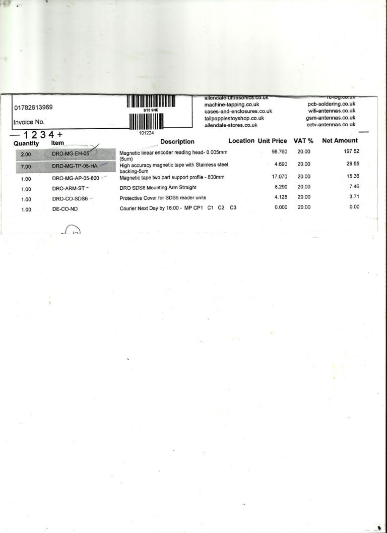
                                      These are the DRO parts I used:-dro parts.jpg

                                      #264063
                                      damian
                                      Participant
                                        @damiannoble34800
                                        Posted by Neil Wyatt on 29/10/2016 21:16:58:

                                        Just noticed this thread has progressed, the Tom Senior looks great Damian! Especially the plates.

                                        You should write it up for MEW

                                        Neil

                                        Thanks Neil

                                        #265816
                                        damian
                                        Participant
                                          @damiannoble34800

                                          Hi all,

                                          I had a couple of days spare before last week away so I got the bit's together for the wiring. A friend came up with a toshiba 0.75kw inverter which would amply power the half hp motor. Also a box for the whole thing.

                                          Wanting push buttons I fitted a couple of 24vdc Omron relays as pictured below.

                                          20161109_150235.jpg

                                          20161109_150251.jpg

                                          The circuit I wired up to is quite simple, a forward and reverse relay as follows. This isolates the control side from the inverter forward/reverse inputs. 

                                          circuit.jpg

                                          The push button station I added to the r/h side of the mill and using two cables wired back to the main panel containing the inverter, forward/reverse relays, 24vdc power supply and a mains 16A breaker. For some strange reason I have lost the knob for the pot so will have to purchase a new one.I can also fit a suds pump switch at a later date when I fit one

                                          20161109_163020.jpg

                                          The whole lot is on a 16A plug so the machine can be isolated if needs be. I would like to fit an isolator in the near future but the machine is up and running. I'm still playing around with the inverter settings as the maximum frequency is 52hz but this is sufficient for most needs.

                                          Here is the box with all the kit in

                                          20161109_163010.jpg

                                          I have used the machine quite a bit and it is a joy to use. Accurate and solid once you take into account the backlash in the X and Y feed nuts.

                                          Next up is to fit a DRO when I get around to it.

                                          Cheers

                                          Damian

                                          Edited By damian noble on 10/11/2016 16:09:37

                                          #265820
                                          damian
                                          Participant
                                            @damiannoble34800
                                            Posted by ian j on 31/10/2016 19:04:33:

                                            Damian.

                                            These are the DRO parts I used:-dro parts.jpg

                                            Thanks Ian

                                            #265844
                                            damian
                                            Participant
                                              @damiannoble34800

                                              Seems as though the prices from allendale have gone up quite a bit for their magnetic read heads sad

                                              #266311
                                              damian
                                              Participant
                                                @damiannoble34800

                                                Here's another pic of the mill fully wired up with all the electrical equipment. As stated above I have enough space to fit a coolant switch on the push button station as well as a work light at a later date if required.

                                                sdc16010.jpg

                                                The soft start in forward and reverse is really smooth. There is enough cable to tilt the head although as other's out there are aware it's best done clockwise as the pulley box foul's on the clamp nuts after about 20deg when rotated anti clockwise with the head fully back.

                                                I have to make some covers for the coolant tray drain holes. I have some recycled stainless sheet that is earmarked for the job.

                                                Damian

                                                #266318
                                                Mike E.
                                                Participant
                                                  @mikee-85511

                                                  I can imagine its a great feeling to have it up and running. smileythumbs up

                                                  #266321
                                                  Emgee
                                                  Participant
                                                    @emgee

                                                    Hi Damian, if you cut a section out of the cabinet lid in front of the VFD readout and glaze on the inside with some clear sheet you will be able to read off motor speed with the VFD set to display RPM, from that calculate spindle speed depending on any ratio of gearing between motor and machine spindle. Just a thought.

                                                    Emgee

                                                    #266346
                                                    damian
                                                    Participant
                                                      @damiannoble34800
                                                      Posted by Mike E. on 13/11/2016 10:29:25:

                                                      I can imagine its a great feeling to have it up and running. smileythumbs up

                                                      It's great finally there Mike. Made a new beefier spider for the scope with it out of ali which was it's first task.

                                                      Been looking at your photos brilliant stuff that was slme workshop as you said in the beacons.

                                                    Viewing 25 posts - 101 through 125 (of 129 total)
                                                    • Please log in to reply to this topic. Registering is free and easy using the links on the menu at the top of this page.

                                                    Advert

                                                    Latest Replies

                                                    Viewing 25 topics - 1 through 25 (of 25 total)
                                                    Viewing 25 topics - 1 through 25 (of 25 total)

                                                    View full reply list.

                                                    Advert

                                                    Newsletter Sign-up