Threading and the tables

Advert

Threading and the tables

Home Forums General Questions Threading and the tables

Viewing 19 posts - 1 through 19 (of 19 total)
  • Author
    Posts
  • #27245
    Russ Bulley
    Participant
      @russbulley69715
      Advert
      #461279
      Russ Bulley
      Participant
        @russbulley69715

        I want someone to educate me!


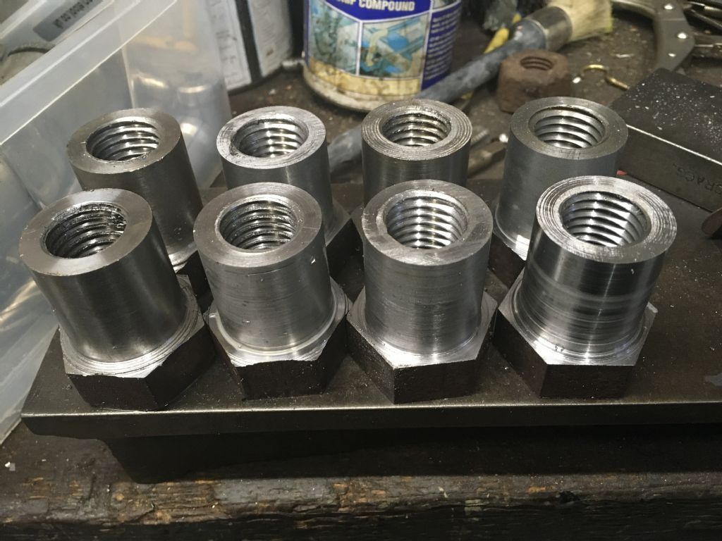
        As I have said before, I am not a professional, learning as I go along, and have just finished 8 x 7/8” 9tpi BSW internal threads about 2” long which has taken about three days.

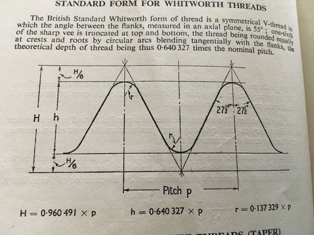
        Now my book (British Standards for Workshop Practice – but this seems to apply to all thread forms and tables) says for nuts medium fit, the minor diameter (which I take as h on the diagram) is between 0.7328” and 0.7620” with a tolerance of 0.0292”, depth of thread 0.0711”. So, I bore to 0.740 +/- 0.003” thinking that’s in the tolerance zone, then thread to 0.071” depth, measured with a DTI on the cross slide. But then I test with a tap, and every single thread was really tight and I had a struggle getting the tap down. All are done now, but what am I doing wrong? By the way I am using a BSW insert cutter.


        I have to say, even when cutting outside threads, I can never get it right, even though I use a DTI on the cross slide and I have eliminated most wear by adjusting gibs etc. What’s the secret of reading the thread data tables?

        Also, if I am using a straight Vee cutter (not a profile insert) the apex of the cutter is actually at H/6 (for BSW) deeper than the bottom of the thread due to the curve. How do you get your depth correct, as you need H/6 + h as a finished height, when you have a tolerance of 0.029”!


        Russ

        Edited By Russ Bulley on 31/03/2020 12:29:54

        Edited By Russ Bulley on 31/03/2020 12:30:16

        #461281
        S.D.L.
        Participant
          @s-d-l

          Can you post a picture of the diagram you are using?

          Steve

          #461304
          SillyOldDuffer
          Moderator
            @sillyoldduffer

            First, I'd work from a tap drill table rather than the theoretical thread form dimensions. I find the tables hard to interpret, especially when tolerances are taken into account. Let someone else do the hard work!

            My drill size tap table suggests a 19.4mm drill for 7/8" BSW – that's about 0.768", which – sanity check – is nearly 30 thou bigger than Russ's 0.740" starting point. It's probably why the tap is so tight – the start hole is too small.

            Depth of thread is 0.64 ÷ pitch, therefore 0.64/9=0.071" which matches Russ's figure. Hooray!

            I'm no expert on threading, but I suggest the lathe is cutting the thread undersize due to the tool shank bending. 2" gives the tool tip plenty of leverage and it tends to cut less deep than the dial suggests. I suppose a professional would measure the actual depth and apply a correction to get to size. I prefer to cut to dial, knowing it's not quite right, and then finish the thread to size by running a tap through. (My goal when threading is to minimise the work the tap/die has to do, not to be more accurate than it. Again, the strategy is to let the tap finish the job so I don't have to do hard sums and tricky measurements.   I only try hard to get threads correct on the lathe when I don't have a tap/die in the right size.)

            How important are the tolerances? For most amateur purposes, they're a red-herring. If tolerances really matter, my answer may be misleading!

            Dave


            Edited By SillyOldDuffer on 31/03/2020 13:55:49

            #461307
            Mick B1
            Participant
              @mickb1

              When you reached the calculated depth of thread, did you run any spring cuts at the same crossslide setting to take out possible deflection of whatever was carrying the threading insert? Assuming all your calcs and settings were correct, that'd be my first check.

              I'm thinking you need to know or calculate the depth of the triangle between the apex of the vee and the crest radius of the standard thread, and add that to your calculated threading depth. That could be the issue.

              And +1 on SOD's comment about finishing the thread off by tap too – it's a far simpler and more reliable way to produce a thread for normal fastening purposes. 


              Edited By Mick B1 on 31/03/2020 14:08:12

              #461321
              Clive Foster
              Participant
                @clivefoster55965

                Almost certainly your tool tip shape is not quite correct. In my experience almost everyone makes them a little too pointed. I certainly did.

                Its almost impossible for home shop guy to grind a single point cutting tip of sufficient accuracy to work to formal tolerances as per the reference books.

                Easiest answer is to revert to the alternative flat top form, its in the books as an official alternative, and adopt a threading technique that allows you to make small, predictable, changes in depth.

                I use the Zero-2-Zero angular in-feed method which has the great advantage that the depth of cut is set to book values before starting using both cross and top slide dials. When both feed dials read zero what you have cut is what you set. If that's not right its very easy to go past zero until the thread is good.

                If you have more than one thread to do the dial zero position can be adjusted to reflect the correct last cut position and all subsequent threads made at that set-up will be correct. The Zero-2-Zero method also automatically sets the correct indeed for the angle at which the topside is set so no maths and the actual set over angle only has to be close. Offset of 25° works fine for me on both Whitworth 55° and Metric / US 60° threads.

                I now use Johanneson / SKF / Dormer chasers originally developed for captan and similar production machines. The cutting edge is formed into two threads of the correct profile. It really is pretty easy to work to book tolerances with these.

                Clive

                Edited By Clive Foster on 31/03/2020 15:07:19

                #461360
                Russ Bulley
                Participant
                  @russbulley69715

                  So thank you for the replies. Yes always do spring cuts. And as I am using Sandvik inserts, think the form will be correct.

                  I did also say these particular threads were internal.715ff0aa-196b-44df-8f69-8c56b3147e22.jpeg

                  4f2e5026-d0d3-42f5-8a84-444aec997ded.jpeg

                  #461375
                  Michael Gilligan
                  Participant
                    @michaelgilligan61133
                    Posted by Russ Bulley on 31/03/2020 12:29:35:

                    […] But then I test with a tap, and every single thread was really tight and I had a struggle getting the tap down. All are done now, but what am I doing wrong? By the way I am using a BSW insert cutter.

                    […]

                    Wild guess, Russ … the Tap may be over-size [i.e. a looser tolerance than you are trying to achieve]
                    Working to the standards that you are ; you should probably be using a Go/NoGo gauge

                    MichaelG.

                    #461384
                    Clive Foster
                    Participant
                      @clivefoster55965

                      Sorry I missed the bit about using inserts in the original post. As you say a full form insert should be dead on the money when it comes to shape.

                      Are you able to run the inserts at book speeds & depth of cut? I've heard tell that there can be sizing issues if you don't run them in the manner they are designed for.

                      Obviously not with threading but I have had experience with cuts being a touch shallow when running an insert too slowly. That particular one was bought in error due to not reading the spec properly and missing the Warp Factor 10 cutting speed. Having made the first few parts running at a sane speed I took my courage in both hands, wound the 1024 up to maximum rpm putting the cutting speed at the bottom of the recommended range and got an undersize part. Light push fit went to free rotating but shake free bearing. Which sounds like the sort of size error you were getting.

                      Clive

                      #461386
                      Russ Bulley
                      Participant
                        @russbulley69715

                        Clive, no I rarely can as I am using suds and at high speed the overspray is terrific. Anyhow charging (9 tpi remember) into a dead end also scares me. So I was using 5 thou increments to try and compensate.

                        To SOD good point, but why is the tapping drill size way off the table? I still don’t understand this tolerance as all I want is a standard thread medium fit!

                        I will measure the tap as suggested.

                        All good stuff guys. So where do you obtain the true machine use data (I acknowledge SODs comments)?

                        Russ

                        #461389
                        Clive Foster
                        Participant
                          @clivefoster55965

                          Russ

                          The Sandvik data book should tell you what speed and depth of cut its designed to run at. Hopefully its one intended for use on a manual machine so the speeds will be within reason.

                          Inserts tend to need an adequate cut to behave themselves so 5 thou may not be enough. Not sure about the spring cuts either. Inserts are supposed to be production tools, to greater or lesser degree, so the makers put considerable effort into producing something that doesn't need the faffing around of multiple spring cuts.

                          Certainly my chasers don't need conventional spring cuts, just a final low feed pass to clean things up to good finish. Which was probably the biggest surprise when I first started using them. I imagine modern inserts will be rather better behaved as being a much more recent development.

                          Realistically I suspect you will need to accept that you won't get perfect results by simply following the thread reference book and will have to tweak the final cut on test to get things just so. The great thing about the Zero-2-Zero method is that it allows you to make small, measured, adjustments whilst getting things right on the first sample and then reproduce the results for the rest of the job.

                          Best practice would be to make notes on the actual in-feed needed to get a right size thread off the machine alongside the thread book value. After a while and several threads you may well find that you have a pattern to the results and will know how much to add right from the start.

                          Clive

                          #461402
                          Hopper
                          Participant
                            @hopper

                            Thread tables and British Standard diagrams etc etc cause way too much angst for use in the home workshop. They describe a theoretically perfect thread suitable only for a theoretically perfect world. You should throw them away.

                            In practice, you are better off to follow SOD's advice and instead calculate your thread depth for BSW or BSF etc as .6403 X pitch.

                            BUT you need to allow working clearance on real world threads. So for external threads, start with the outside diameter at least five thou smalller than the nominal size. So a 1/2" thread would have an actual diameter of .495". For larger threads, increase this clearance. A 1" diameter thread I would probably make outside diameter .990", so ten thou clearance.

                            Ditto internal threads. Make the hole up the middle five to ten thou larger than the nominal root diameter. And you find your nominal root diameter by deducting two thread depths (as calculated in the above formula.) from the nominal OD of the external thread.

                            Final sizing is done by try and fit with the nut or bolt the part is going to mate with. Or by using a tap for the final few thou if available. No shame in that. Quick and effective is always the best way of machining.

                            Get any of the old books by the old timers who screwcut all their lives without ever using a BS drawing in the workshop and learn the way screwcutting was done on manual lathes for the past 100 years or more. It is quite simple. Recommended: The Amateurs Lathe by LH Sparey for basics and Screwcutting in the Lathe by Martin Cleeve for more than anyone ever really wanted to know on the subject. .

                            #461405
                            Nigel Graham 2
                            Participant
                              @nigelgraham2

                              By corollary I use a die to trim the top of a cut external thread.

                              It's worth remembering that an insert tool or a chaser will only cut true rounded crests if the thread requires the full depth of the tool.

                              A tip for depth-gauging. If possible make the part a bit over-length and turn the surplus section to a few thou' above (male thread) or below (female) root diameter. When the threading tool just starts to scratch that, you are almost there. Take a couple of spring cuts then test with the mating part – or if a standard thread, a new screw. Or finish the thread with a tap or die (preferably a die-nut?)

                              Spring-cuts – I normally take one every couple of passes to ease the growing load on the tool, especially when using straight-in cuts.

                              Also, I do question this matter of carbide tips "needing" to be run at high speeds. They are indeed made to clear metal at alarming rates, but in industrial production conditions on massively-built CNC machines; and their individual designs are to suit particular materials. I have not had unduly poor finishes using insert tooling at modest rates. If the finish is poor I blame my tool-setting or using a slightly worn or mis-chosen insert, or using "new-to-me" steel of unknown provenance, before the tool per se.

                              #461409
                              Hopper
                              Participant
                                @hopper
                                Posted by Nigel Graham 2 on 01/04/2020 00:13:39:

                                It's worth remembering that an insert tool or a chaser will only cut true rounded crests if the thread requires the full depth of the tool.

                                That's certainly true. But I never worry about getting the perfect tip radius etc — that is all part of the angst brought about by looking at BS thread form drawings and the like. As Tubal Cain points out in his ME Handbook, you get something like 95 per cent thread strength with only 65 per cent thread engagement. What you want on the tips and roots of your threads is working clearance. So if the radius has a bit of a flat on the top of it, or is just one big flat, no big deal at all. In fact its good, because its providing working clearance and ensuring the thread is engaging on the flanks as it should do, and not on the tips and roots.

                                If we were making wing pivot bolts for space shuttles, things might be different. But for general work, not so. Horses for courses.

                                #461462
                                Howard Lewis
                                Participant
                                  @howardlewis46836

                                  If you do as Hopper suggests and truncate the thread, (Very slightly Undersize for External, Oversize for Internal) you don't need to worry about getting the correct crest or root radius. It won't be there.

                                  As an Apprentice, we were taught to truncate threads, to prevent interference between root and crest.

                                  There is always a lot of discussion about Tapping size vs % engagement of threads. A reduced engagement, say 65% against 75% will not matter in most of the work that we do. We are not deliberately going to tighten fasteners into yield, for hobby work.

                                  Tolerances become important when making mating parts in volume, so that all have to be capable of being interchangeable with all the others. That's why the BS charts, and drawings, quote tolerances.

                                  But, at the extremes of tolerance, you can have parts within drawing tolerance, but producing fits that vary between tight and loose. If the tolerance on both parts are + / – 0.001, with a nominal 0.003 clearance, you could finish up with only 0.001 clearance or 0.005 if the mating parts are at the extremes of the tolerance band.

                                  Howard

                                  #461468
                                  Hopper
                                  Participant
                                    @hopper
                                    Posted by Howard Lewis on 01/04/2020 10:27:22:

                                    As an Apprentice, we were taught to truncate threads, to prevent interference between root and crest.

                                    Exactly where I learned it. I vaguely remember seeing a Standard thread form drawing at tech college but they were certainly never referred to on the machine shop floor. The only crest radius in sight might have been from running a file down the thread to knock the burrs off.

                                    I think the angst about radiuses and perfect forms has come about with the availabiliity of readymade full-form carbide inserts designed for use in production CNC work which is a whole different ball game. We just ground our own HSS tools and rubbed the tip on an oilstone a few times to round the end to stop edge chipping. Those were simpler times I guess.

                                    #461523
                                    SillyOldDuffer
                                    Moderator
                                      @sillyoldduffer
                                      Posted by Russ Bulley on 31/03/2020 20:58:38:

                                      To SOD good point, but why is the tapping drill size way off the table? I still don’t understand this tolerance as all I want is a standard thread medium fit!

                                      All good stuff guys. So where do you obtain the true machine use data …

                                      Russ


                                      I have a number of reference books. They vary a bit depending on the target audience, for example a tool-maker or draughtsman might need all the gory details, a professional might need a few fits, while the amateur wants to keep it simple.

                                      The Model Engineer's Handbook (Tubal Cain) is a good basic reference. He gives one figure for 7/8" BSW tap – 19.5mm.

                                      I have a Newnes Engineer's Reference Book which is a bit more grown up. For 7/8" BSW tap drills it suggests:

                                      • 47/64" for a Class A (Close Fit),
                                      • 3/4" for a Class B (Medium Fit), and
                                      • 49/64" for a Class C (Free Fit)

                                      Tubal Cain recommends 19.5mm for Model Engineering. That's 0.768", rather looser than a Newnes Class C Free Fit ( 0.7656" )

                                      Another good book (second-hand) is Machinery's Handbook from the USA. Mine is the 20th Edition, which does US, British and Metric. 2480 pages of light reading! It recommends a 19.25mm tap drill for 7/8" BSW ( 0.7579" ), which lies between Newnes Class B and Class C fits. Machinery's is lightweight on BSW, obsolescent in 1975, but it does detail on Metric and Unified Screws.

                                      So variations in the Engineering literature! Where did your table come from? It's not unknown for mistakes to creep in.

                                      As others have noted, a BSW thread made fully to specification would have rounded valleys and peaks. However, it's common for lathe cut BSW threads to ignore the rounded top, and for the operator to gently flatten the tips off with a file. In the USA they decided Whitworth's rounded top didn't add much value and simplified NS by specifying a flat top. Metric did the same.

                                      What this boils down to is how important the fit is; what's it for? A safety critical thread will be made to a high-standard but for many ordinary purposes threads are made slack. Loose threads are preferred when ease of assembly matters more than maximising strength. In practice, most fasteners are on the slack side.

                                      The tolerance thing is confusing. They're specified for inspection purposes. When I make a batch of threads it rarely matters if some are tight and others loose. As long as they fit together I'm happy. Not so in manufacturing, where interchangeability matters. Gauges are used to confirm threads are made within tolerance, ie not too big or too small for some defined purpose. Machines are set to make threads within a tolerance band, and readjusted as the tools wear, and again when the tool has to be changed. Although the resulting threads can be a long way off perfect, the variation is under control and acceptable within limits. Few of us need to work that way.

                                      Dave


                                      Edited By SillyOldDuffer on 01/04/2020 14:34:38

                                      #461598
                                      Russ Bulley
                                      Participant
                                        @russbulley69715

                                        I want to say thank you to everyone for the contributions above. Very helpful!

                                        Russ

                                        #461618
                                        S.D.L.
                                        Participant
                                          @s-d-l

                                          From memory when we used to use sandvik internal boring bars the shim under the insert has to be different angles for different TPI inserts, there were at least 3 angles maybe more. I suspect for the feed in to be to theory dimension the angle needs to be correct.

                                          Steve

                                        Viewing 19 posts - 1 through 19 (of 19 total)
                                        • Please log in to reply to this topic. Registering is free and easy using the links on the menu at the top of this page.

                                        Advert

                                        Latest Replies

                                        Home Forums General Questions Topics

                                        Viewing 25 topics - 1 through 25 (of 25 total)
                                        Viewing 25 topics - 1 through 25 (of 25 total)

                                        View full reply list.

                                        Advert

                                        Newsletter Sign-up