table drive motor identification

Advert

table drive motor identification

Home Forums Manual machine tools table drive motor identification

Viewing 25 posts - 1 through 25 (of 26 total)
  • Author
    Posts
  • #95638
    ronan walsh
    Participant
      @ronanwalsh98054

      The x-axis power feed on my tom senior universal mill is powered by an electric motor rather than mechanical means. I ideally want to power this motor from the usual inverter/vfd, can anyone help me identify what type of motor i have ? it can be seen in the pictures in my album. The main motor has been disconnected from the electrical board in the base and connected temporarily to the vfd i use for my lathe so the machine is operable, but i would like to get the table feed sorted.

      p.s its the one with the "kemo" nameplate.

      thanks.

      Edited By ronan walsh on 02/08/2012 23:50:14

      Advert
      #11976
      ronan walsh
      Participant
        @ronanwalsh98054
        #95642
        Anonymous

          Hmmm, I suspect that the A and F on the nameplate stand for armature and field, which implies it's a DC motor. The fact that the armature and field list different voltages and currents may mean that it's a shunt wound DC motor. Therefore driving it with a VFD will not work. It's not uncommon to use DC motors for table drives; certainly a lot of Bridgeport mills do so.

          Regards,

          Andrew

          #95645
          ronan walsh
          Participant
            @ronanwalsh98054

            Thanks for your reply andrew, I may replace this motor with a ac type and drive it with a vfd so. Is there any other method of operating this motor from a single phase supply ? There is quiet a lot of electronics in the board in the base to operate this motor, but i don't have a three phase supply and don't intend to get it.

            #95647
            Michael Gilligan
            Participant
              @michaelgilligan61133

              Ronan,

              If you are reworking the electrics; this seems a good time to replace that motor with a Stepper.

              MichaelG.

              #95653
              Les Jones 1
              Participant
                @lesjones1

                Hi Ronan,
                I think Andrew is correct that this is a DC shunt wound motor. (It had not occured to me that A & F stood for armature and field.) From these voltage ratings I think it's controller is run from 230 volts. (Between neutral and one of the three phases.) I think the electronics board on the right hand side of your picture is the speed control for this motor. I think for a table feed motor the DC motor is better than a three phase motor with a VFD as it will have better low speed torque. Also to use it only requires it to be connected to your single phase supply.

                Les.

                #95657
                Versaboss
                Participant
                  @versaboss

                  Fully clear that this is a DC motor; look at the == sign after the voltage values!

                  Greetings, Hansrudolf

                  #95675
                  Anonymous

                    A recent thread discussed driving a 230V DC motor, **LINK**

                    I can't see any reason for changing to a stepper motor, a lot of mechanical work, as well as changing the drive electronics, and fitting a hefty power supply.

                    Regards,

                    Andrew

                    #95680
                    Ex contributor
                    Participant
                      @mgnbuk

                      Does the original motor/drive not work ?

                      One of your photos shows what appears to be a basic DC drive – if the motor & drive are working I would leave them be for the moment & use the machine "as is".

                      FWIW I would not look to replacing the current arrangement with a 3 phase motor / VFD combination. Unless you fitted an external fan to cool the motor, I suspect it would overheat at low speeds. Should the motor die (replacement drives are easy enough to source for small dc motors if the drive dies), I would be looking for a small dc or ac servomotor & drive, as these are designed to supply their rated torque down to a standstill & would be quite happy running at low speeds for extended periods.

                      Regards,

                      Nigel B.

                      #95681
                      ronan walsh
                      Participant
                        @ronanwalsh98054

                        Firstly , thanks to all for replying to this thread , i didn't know i could power this motor from single phase power. This is a relief as it saves me altering the machine and also the cost of a vfd. Heading to the shed now to investigate this.

                        Thanks.

                        #95684
                        ronan walsh
                        Participant
                          @ronanwalsh98054

                          I have upped more photos of the electrical board. if i were to change the transformer in the top left hand side of the board to a 240v -24v out would that work ? the components on the two boards seem to be 12 and 24 volt pieces.

                          #95687
                          Michael Gilligan
                          Participant
                            @michaelgilligan61133
                            Posted by Andrew Johnston on 03/08/2012 13:50:18:

                            I can't see any reason for changing to a stepper motor

                            Andrew,

                            That's strange … I can see several

                            However; I did qualify my post with "If you are reworking the electrics". Since it now appears that the original motor is useable, I agree with your recommendation.

                            MichaelG.

                            #95691
                            Michael Gilligan
                            Participant
                              @michaelgilligan61133
                              Posted by ronan walsh on 03/08/2012 16:21:10:

                              I have upped more photos of the electrical board. if i were to change the transformer in the top left hand side of the board to a 240v -24v out would that work ? the components on the two boards seem to be 12 and 24 volt pieces.

                              Ronan,

                              Do you mean this one ?

                              … if so, it's already 240V input.

                              (confused)

                              MichaelG.

                              #95694
                              ronan walsh
                              Participant
                                @ronanwalsh98054

                                Yes michael ,thats the one, can i simply connect the live and neutral single phase to this ? , there is a contactor block immediately below this which has three phases connected to it , can this be isolated ? Surely its for the main drive motor which is now not connected to this board as its connected to a vfd.

                                #95696
                                Les Jones 1
                                Participant
                                  @lesjones1

                                  Hi Ronan,
                                  I suspect the board on the left with the transformer and relays is for controlling the main motor. I think the transformer just provides 24 volts for the relay coils. It probably deals with interlocks and the start/stop buttons. I think the board on the right is the speed controller for the table feed motor. After looking at more of the pictures I have changed my opinion. I think the left hand board is to do with the table feed motor. I think the main motor was controlled by the contactors on the left of the electrical box.

                                  Les.

                                  Edited By Les Jones 1 on 03/08/2012 18:55:17

                                  Edited By Les Jones 1 on 03/08/2012 19:02:46

                                  #95697
                                  Michael Gilligan
                                  Participant
                                    @michaelgilligan61133

                                    Ronan,

                                    Subject to every caveat in the book …

                                    It looks like you can isolate this lot from the 3-phase and simply wire into 240V

                                    BUT… we need to see a bit more of the wiring … this is a only a small transformer and certainly isn't powering the Motor!

                                    Do you have any idea whether this is a standard Tom Senior, or a Special ?

                                    MichaelG.

                                    #95698
                                    ronan walsh
                                    Participant
                                      @ronanwalsh98054

                                      Thanks les, i should have said that this machine came from a community college and is covered in safety switches , one on nearly every door or hatch and a massive emergency stop foot operated button on the base. There is a lot of wiring from these switches to the board. I may remove them as they don't serve any real purpose.

                                      if anyone can steer me on how to get this table motor running with the original buttons and controls i'd be very happy.

                                      #95701
                                      Les Jones 1
                                      Participant
                                        @lesjones1

                                        Hi Ronan,
                                        Without having access to the machine to trace the wiring (Or a full circuit diagram of how the machine was originally wired.) I can't tell you how to get it working. I assume that as the main motor is now fed from the VFD on your lathe that there is no power connected to the original electrical box. If this is the case then I suspect that if a single phase supply was connected to neutral and the phase that was used to feed the table feed motor then the motor would work.

                                        Les.

                                        #95713
                                        ronan walsh
                                        Participant
                                          @ronanwalsh98054

                                          thanks les , i'll contact denfords for a wiring diagram, they do have some drawings because they bought tom senior's in the early 80's and i will also ask over on the yahoo group for senior millers.

                                          #95749
                                          ronan walsh
                                          Participant
                                            @ronanwalsh98054

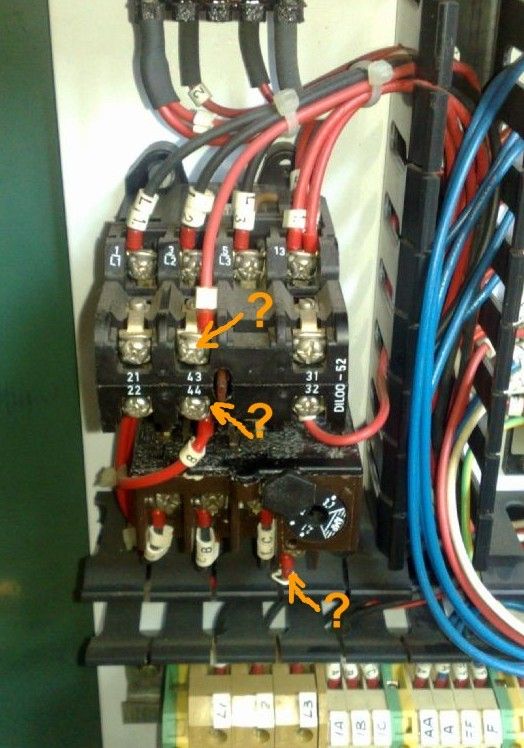
                                            I finally got the power feed working , i have upped two photos showing how, one of the three lives ran from L3 to L on the connections at the bottom. i disconnected this and connected a single phase live to the L connection on the right (beige coloured block) the neutrals are common as are the earths so these were connected also. With power applied the motor worked but only after the contactor in the second last picture was pushed in manually.

                                            The motor isn't that fast running , even with the rapid feed button held down , but hey it works and the limit switch mounted on the front of the table works perfectly too.

                                            So if anyone can tell me how do i get around having to push in the contactor manually ? can i do away with this component completely ?

                                            Thanks all .

                                            #95759
                                            john swift 1
                                            Participant
                                              @johnswift1

                                              Hi Ronan ,

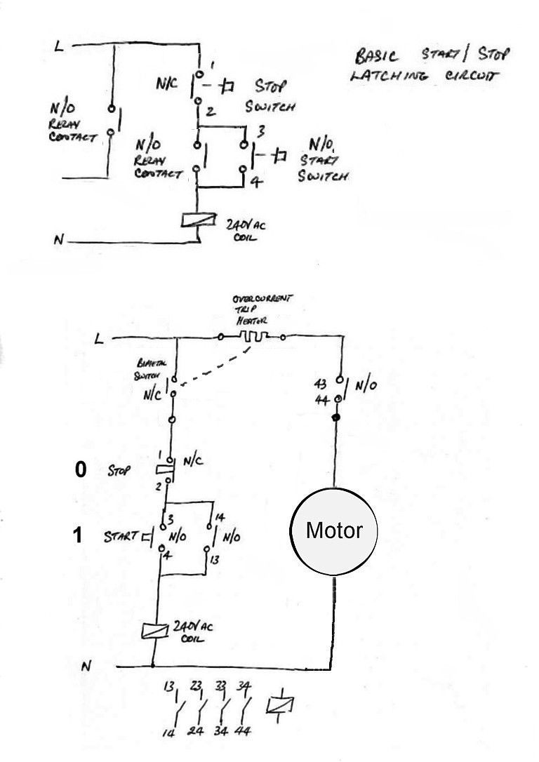
                                              assuming the contactor has a 240V coil

                                              you should find the neutral is connected to one end of the coil

                                              and when you press the normally open green start button

                                              the live supply is connected to the coil via the now closed start switch , the normally closed stop switch and the overload switch

                                              once the contactor pulls in , a normally open pair of contacts wired in parallel with the start switch closes and maintain the power to the coil until the stop switch is pressed

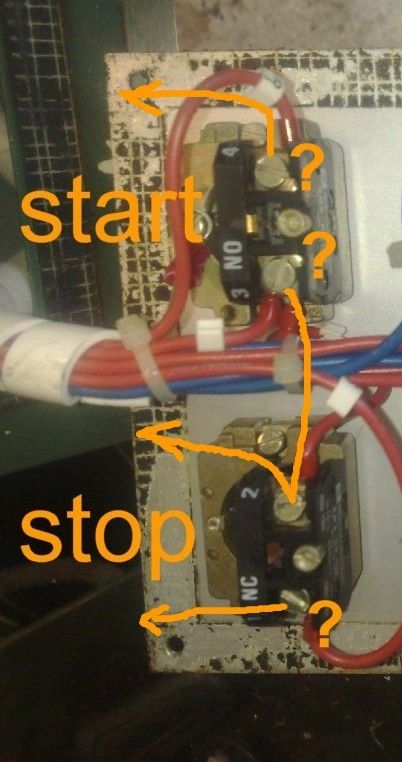
                                              you need to trace the three wires from the start and stop switches to see how they are connected to the contactor

                                              hopefully my diagram will help

                                              John


                                              motor stop-start nvr.jpg

                                              n-o start n-c stop buttons.jpg

                                               possible wires from start stop switches.jpg


                                              Edited By john swift 1 on 04/08/2012 20:30:16

                                              #95764
                                              Les Jones 1
                                              Participant
                                                @lesjones1

                                                Hi Ronan & John,
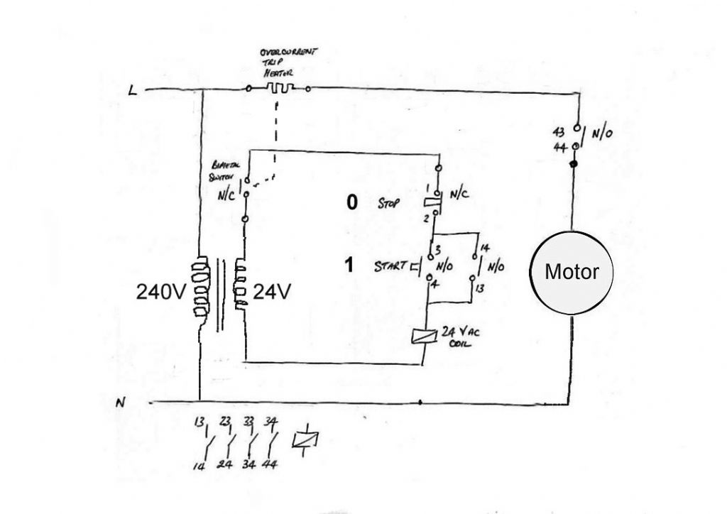
                                                I suspect the relay associated are 24 volt. It could be that the motor was powered from one phase and the transformer that is used to power the relays is fed from another phase. I may be necessary to connect your single phase to two (Or even all three of the phases.)

                                                Les.

                                                #95769
                                                john swift 1
                                                Participant
                                                  @johnswift1

                                                  Hi Les

                                                  Good point about the transformer

                                                  the control could be more like this :——motor stop-start nvr 24v coil.jpg

                                                  john

                                                  #95775
                                                  ronan walsh
                                                  Participant
                                                    @ronanwalsh98054

                                                    Thanks for the trouble everyone has gone to on this , I have successfully managed to delete the wiring that was no longer required and the contactor block, the wiring comes directly from the rail on the bottom of the board, into the 240v-24v transformer on the top of the board, the power (24v) then runs back down to the rail connections , i didn't have to touch the actual electronic pcb's at all thankfully.

                                                    It all works fine now and i am very happy not to have to fork out for a new motor or vfd.

                                                    One piece of the contactor is remaining , i didn't know if i should remove it or not , advise please. Its in the last couple of picture i have just uploaded.

                                                    #95800
                                                    Les Jones 1
                                                    Participant
                                                      @lesjones1

                                                      Hi Ronan,
                                                      I can not advise you on removing that contactor just from the pictures. You would have to provide a diagram of the wiring to determine what iot does.

                                                      Les.

                                                    Viewing 25 posts - 1 through 25 (of 26 total)
                                                    • Please log in to reply to this topic. Registering is free and easy using the links on the menu at the top of this page.

                                                    Advert

                                                    Latest Replies

                                                    Home Forums Manual machine tools Topics

                                                    Viewing 25 topics - 1 through 25 (of 25 total)
                                                    Viewing 25 topics - 1 through 25 (of 25 total)

                                                    View full reply list.

                                                    Advert

                                                    Newsletter Sign-up