Stuart Twin Victoria (Princess Royal) Mill Engine

Advert

Stuart Twin Victoria (Princess Royal) Mill Engine

Home Forums Work In Progress and completed items Stuart Twin Victoria (Princess Royal) Mill Engine

Viewing 25 posts - 701 through 725 (of 1,260 total)
  • Author
    Posts
  • #607360
    Dr_GMJN
    Participant
      @dr_gmjn

      Thanks all!

      Ramon – rained on the way down, but, as usual, warm and fairly sunny where we’re staying. Been coming here for 15 years or so, and can count on one hand the number of rubbish weather days we’ve had. Locals say it’s something to do with the Gulf Stream:

      Jason, plan is to get some hex bar, cut it to the overall length of the combined nut and lock nut, then machine a fake joint line around it. Then the flats will line up perfectly*

      Hopper – I just used the upper and lower thicknesses based on the last image I saw of lock nuts on a steam engine. What is the theory behind the thin/thick orientation? I did a course on bolt science a few years back, and the theory and practice of bolted joints is anything but simple. The person who ran the course (very good – PhD, also hands-on, expert witness for this kind of thing etc., etc.) said that in his experience, the only consistent method of stopping nuts or bolts loosening when subjected to a Junker test, was a Nord-Lock washer. This included testing lock wires, Loctite, lock nuts, even weld dots. Of course, in a well designed joint – with no relative movement between the mating faces) pretty much any method will work, because there will be very little tendency to un-tighten in the first place.

      * only joking

      Edited By Dr_GMJN on 25/07/2022 21:51:09

      Advert
      #607376
      Hopper
      Participant
        @hopper
        Posted by JasonB on 25/07/2022 18:28:49:

        For those that like looking at old nuts this is the "handbook on steam engines" that Doc mentions, interestingly the third edition published in 1902 shows locknuts below full nuts and some washers too

        Which shows that it is perhaps an older chestnut than even Ramon suspected. All my old books show it other way round. So it seems unlikely the debate will ever be settled!

        #607378
        Hopper
        Participant
          @hopper
          Posted by Dr_GMJN on 25/07/2022 21:50:57:

          Thanks all!

          Hopper – I just used the upper and lower thicknesses based on the last image I saw of lock nuts on a steam engine. What is the theory behind the thin/thick orientation? I did a course on bolt science a few years back, and the theory and practice of bolted joints is anything but simple. The person who ran the course (very good – PhD, also hands-on, expert witness for this kind of thing etc., etc.) said that in his experience, the only consistent method of stopping nuts or bolts loosening when subjected to a Junker test, was a Nord-Lock washer. This included testing lock wires, Loctite, lock nuts, even weld dots. Of course, in a well designed joint – with no relative movement between the mating faces) pretty much any method will work, because there will be very little tendency to un-tighten in the first place.

          There is a rundown on some Junkers testing here LINK

          NB the "Word of Warning" at the bottom of the piece pointing out that there may be other factors involved that can sometimes justify thin nut on the top, including on long studs — such as those found on old steam engines.

          The reason I believe it is a 21st century development, or thereabouts, is when this was discussed on a previous thread I found there is an ISO standard dated 2012 on the topic ( section 5 of ISO 898-2: 2012 Mechanical Properties of Fasteners made of Carbon Steel) , Whereas my old 1970s books from when I studied to take the government marine engineer's certification examination – a very stringent exam to ensure that ships don't break down at sea and sink etc and considered equivalent to an engineering degree if you pursue it to chief engineer exam level — still specified the thin nut on top as the only acceptable procedure on large marine engines. It was an archaic exam that still covered reciprocating steam engines and Weirs feed pumps etc, all drawn with thin nuts on top.

          So apparently thin nuts on top — mandated by government regulation and checked by Lloyds surveyors regularly —  kept ships running around the globe throughout the 19th and 20th centuries without connecting rods coming adrift with any regularity.


          Edited By Hopper on 26/07/2022 00:39:14

          #607381
          PatJ
          Participant
            @patj87806

            I think the reason that the thin nut on top works is that the thick bolt is torqued to some value, pushing the nut threads against the bolt threads on one side.

            Then when the thin nut is added, it is not torqued to the same value as the thick nut, rather it is only torqued enough to prevent rotation of the two nuts.

            If the thin nut were torqued as high as the thick one, then the thin nut would assume all of the load.

            I think that is why the thin nut on top works; because it is not overtorqued.

            .

            Edited By PatJ on 26/07/2022 05:04:57

            #607387
            Ramon Wilson
            Participant
              @ramonwilson3

              Ha ha – here we go again. Sorry guys but this ones been done to death for me so I'll bow out gracefully on the technicalities .

              I will say this though from a personal point of view. Whilst I think I can understand the theory behind the thin nut first having the thin nut on top always looks aesthetically better to my mind – wrong or not.

              I guess in the end it boils down to whether you are are 'nuts on top' or 'nuts below' kind of person.

              A couple of scenarios –

              Model on display with the 'correct' thin nut underneath method. Inquisitive visitor asks why the nuts are the wrong way round. Watch their eyes glaze over as you try to explain why.

              Model on display with nuts thin nut on top. 'Knowledgeable' visitor proceeds to tell you you have the nuts on the wrong way. You tell visitor – in a polite manner of course – that whilst fully aware of the theory they are that way because it's your model and you prefer them that way

              Bye for now on this one.

              Doc – we were North Wales visitors on a regular basis for many years and saw all weathers. Most memorable was sitting on one top in lovely sunshine watching a vicious storm take place on another not that far away. Looks like you have some nice weather – enjoy it

              Best – R

              #607392
              Hopper
              Participant
                @hopper

                Sorry I didn't mean to hijack the thread. The link I posted above lays out the science behind modern thinking. The link Jason posted to the old book shows that in steam engine days, some manufacturers did it one way, others did it the other. So there really is no right or wrong way. I am with Ramon though that thin on top looks "right" to me.

                All moot in this day of Loctite threadlocker anyway!

                There are multiple past threads on the topic available to be searched for anyone interested, rather than derailling Doc's build thread here.

                #607454
                Dr_GMJN
                Participant
                  @dr_gmjn

                  All – I wouldn’t call it a thread hijack at all. I’m totally ok with discussions like this. My day job is engineering, but obviously not machining or model engineering…I learned a long time ago that it’s daft to pretend to know everything about the subject (although believe me, some people seem to think they do!). Every day is a school day and I appreciate a decent discussion and any advice (like Hopper’s thoughts on d.i.y. ML7 bed refurbishment a while back that a) worked a treat, and b) saved me a hell of a lot of money on re-grinding.

                  Hopper – it was actually Bill from Bolt Science who did our course at work. Very, very good person to know for anything like this. Interesting to note that even the best combination of lock nut seems to give a preload reduction of about 2/3.

                  Ramon – seems like we’re both of similar opinions about prototypical accuracy, at least with things like this, and my enthusiasm for washers. At the end of the day, I’ll weight up my own version of what looks nice to me, now knowing the theory and history, and take it from there. It’s not the end of the world to change them later.

                  Anyway, I’ll finish my cup of tea and head back out on the island to see what’s what. The day visitors have gone, so there’s only a handful of humans left – perfect weather down here again, but forecast to be cloudy tomorrow…

                  #608024
                  Dr_GMJN
                  Participant
                    @dr_gmjn

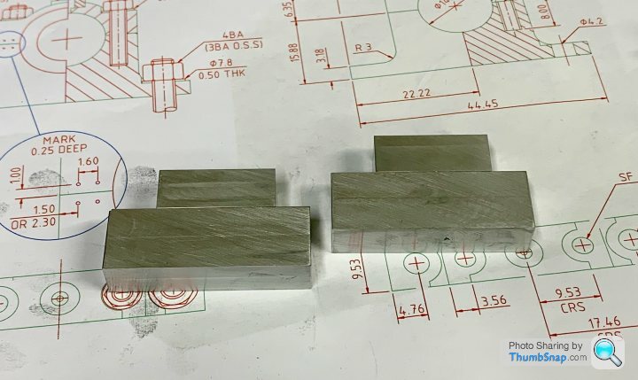
                    Home again. Today I machined the new blanks:

                    Hopefully not too long before some progress is made again.

                    #608045
                    Ramon Wilson
                    Participant
                      @ramonwilson3

                      Better luck this time Doc, hope you had a good break.

                      Best – R

                      #608689
                      Dr_GMJN
                      Participant
                        @dr_gmjn

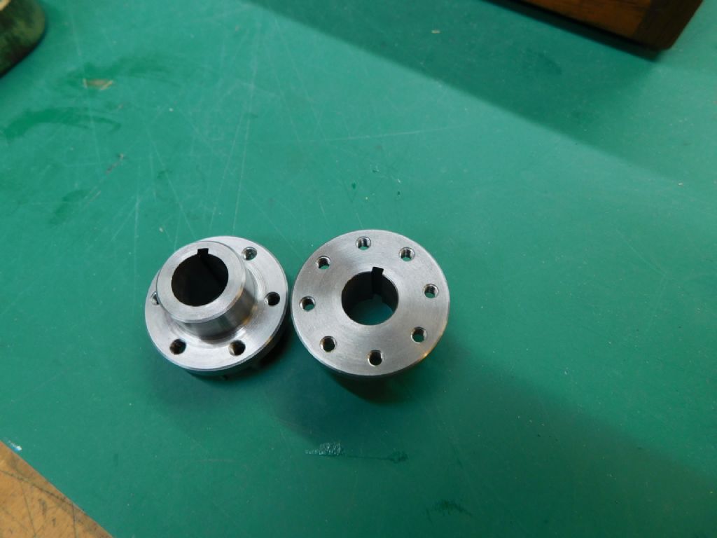
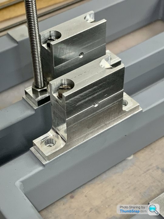
                        Been a bit sidetracked this week, but at least got back to this stage where the blocks are drilled and tapped. I sacrificed some bolts and put gates in them to make loosening/tightening easier – as mentioned before regarding M3 capheads:

                        #608793
                        Dr_GMJN
                        Participant
                          @dr_gmjn

                          On a related subject – the crakshaft. I've sketched up a stepped version here (original at the top, stepped below):

                          I'm not sure how the key/keyway works on this model, something about tapered keys, but basically I've extended the original keyway over into the adjacent step for the eccentric. I don't think (so far) it will make any difference, and when assembled, visually the keyway will end at the eccentric face:

                          At the other side, I've not stepped the shaft for the governor pulley, becasue this will be aluminium, and won't damage the steel shaft, so presumably that will be OK. I might widen the pulley to eliminate the slight gap at that side too (or even make it overall narrower to give a more 'spaced' effect):

                          The bearing diameter is as per the plans, with the steps at increments of 1mm increase in diameter. I've shown the centre drillings at each end (should be in a partial section I know), but I wanted to show them since I assume the full sized crank would have had centre drillings too?

                          Apologies for the poor quality of the screen shots, I've yet to figure out image export from QCAD.

                          Comments welcome as always. Thanks.

                          #608795
                          JasonB
                          Moderator
                            @jasonb

                            It would be a lot easier to go with a parallel key and a discrete grub screw in the flywheel hub to bear on the key. It is not so easy to cut a tapered keyway in the flywheel bore though there are a couple of ways to do it. There is also quite a bit of work getting the tapered key to fit correctly so it locks the flywheel in place though it is the true way to do it and satisfying when done.

                            Quite a few full size engines don't have a ctr at the ends of the shaft though some do. I usually don't hove them, you can make the shaft overlength for machining and then once all assembled and test fitted the excess length can by machined away to remove the ctr drill hole(s)

                            #608798
                            Ramon Wilson
                            Participant
                              @ramonwilson3

                              Yes, I'm with Jason on the (non) use of a tapered key. If you use the saddle to cut it in the flywheel you can't cut it at an angle anyway. How do you plan to cut the keyways in the parts to be fitted BTW

                              If you cut the keyway parallel and you can slightly taper the key by careful filing until it tightens in the right spot but it will only be on the high point of course. A parallel key with a tiny grub screw is much the better option – the key does the driving, the screw just enough to keep it in place laterally.

                              I have just cut the keyways in the coupling and flywheel drive ends on the Marine Compound. The issue how to hold them in place poses the same question so a discreet grub-screw it is.

                              Same with the centres – either is correct – just depends on your view. Bear in mind though if they are to be left in then they do need to be quite small to be in scale. If you turn the ends away it usually has to be done using a fixed steady if you cant get the shaft up the spindle.

                              Regards – R

                              #608806
                              Dr_GMJN
                              Participant
                                @dr_gmjn

                                Thanks both, but having re-familiarised myself with the article, I’m not sure we’re talking about the same things?

                                As I read it, the keyways on the shaft and wheel are parallel, not tapered in any way. There are two, at 120 degrees to each other. The article suggests one may need to have a stepped key due to the difficulty of cutting the keyways to the necessary angular accuracy using just a lathe. I assume I can mill my shaft keyways precisely with the R/T, and in the wheel by making (probably printing) a device to rotate the chuck by exactly 120 degrees. The keyway in the wheel being made with a cutter traversed by the saddle handwheel.

                                The key is as shown:

                                They are tapped into position into the wheel (from the unobstructed left side (opposite the governor pulley) until a set gap is left between the ‘head’ and the boss flank. One key is full boss width, the other a much shorter ‘dummy’. Both are held in place by small grub screws.

                                I’ve never cut a keyway before either in the mill or by traversing the saddle, but either method doesn’t seem that difficult – maybe I’m underestimating the task (for once!)?

                                The only slight modification I can think of would be to mill a small flat onto the tapered key for the group screw to sit square on. Maybe even this is unnecessary?

                                Cheers.

                                #608810
                                Paul Kemp
                                Participant
                                  @paulkemp46892

                                  Your drawing there shows the top face of the key tapered by 1 in 100. It is what is normally termed a gib key. The keyway in the shaft is parallel in all directions the top of the keyway in the flywheel should be cut to the same taper. The key is then hammered home and the tapers lock to ensure the flywheel is fixed. If that makes sense? To cut the tapered keyway in my TE flywheel I made the broach bush to the required taper such that when broached (in the right direction!) the top of the key way is automatically tapered. You can check the mating fit on assembly with engineers (micrometer) blue, not marking blue!

                                  Paul.

                                  #608811
                                  Dr_GMJN
                                  Participant
                                    @dr_gmjn

                                    Thanks Paul, it makes sense, but the drawings show non-tapered keyways on both the shaft and hub in all directions.

                                    It states that the key taper must be filed until a (specified, but can’t remember) gap is present between the key head and the boss, when the key is tapped home.

                                    I understand the theory of the method you describe, but presumably at full size that wouldn’t require a grub screw to secure? This suggests to me that the P.R. method is to give the appearance of a properly tapered assembly, but without the requirement to make a tapered keyway?

                                    I can’t imagine that using a tapered key, parallel keyways and a securing screw will ever cause any location or shear issues with a model such as this, even though it might not be full-size engineering practice?

                                    #608814
                                    JasonB
                                    Moderator
                                      @jasonb

                                      Like Paul I do mine with a broach and have made several bushes that guide the broach at an angle and these hold well. It is also possible to do it with a slotting attachment on a lathe but you would need to make one of those. The key is either bought or made and then fitted to the assembled parts to ensure good contact. All my hit & miss model engines and quite a few of the steam ones use tapered keys into tapered keyways and that is all that holds the flywheel on, it's quite satisfying hearing the note of the blows change as the key tightens into place (copper face hammer)

                                      The problem with driving a wedge into a parallel keyway is that it can tilt a flywheel sideways particularly if there is a bit of slack in the fit onto the shaft, two keys will reduce this but they still won't have much to hold against so could work loose hence the grub screw..

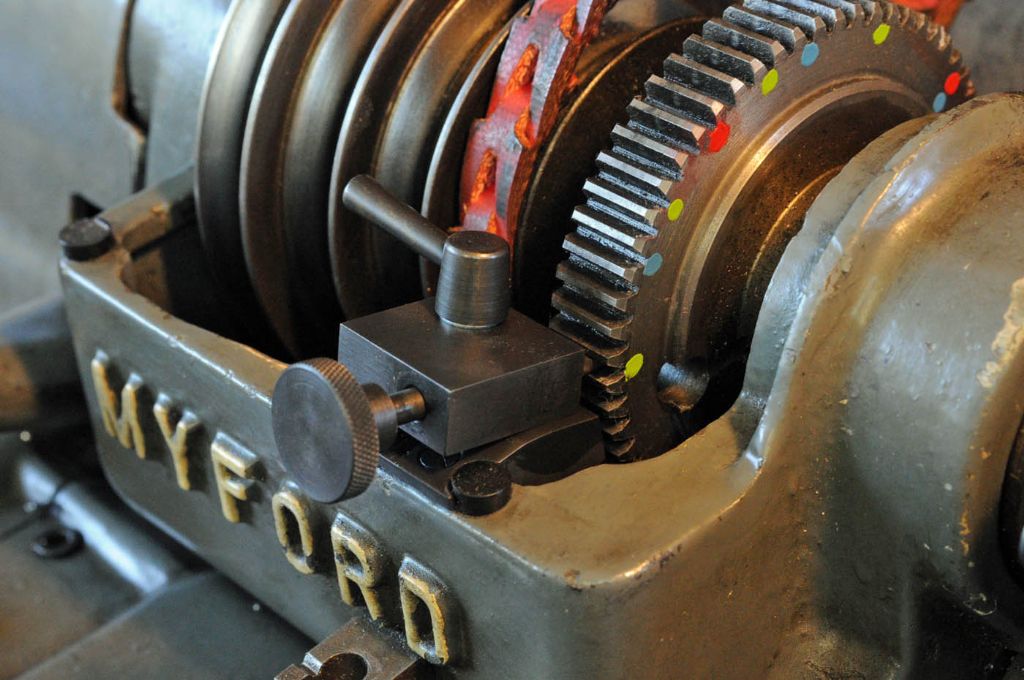
                                      Index the flywheel either with the bull wheel on your Myford or simply make use of the chuck jaws which are at 120deg spacing

                                      If you do buy your gib head keys rather than make then your drawing shows a metric one with 1:100 taper, imperial width ones have imperial taper of 1:96 (1/8th inch to the foot.)

                                      You don't want to tap the key in so far that the head touches the side of the flywheels hub, there should be a gap so that you can get something in to extract the key. A banana drift is the ideal tool but a pair of flat bladed screwdrivers also work as folding wedges.


                                      Edited By JasonB on 09/08/2022 07:07:38

                                      #608820
                                      Ramon Wilson
                                      Participant
                                        @ramonwilson3

                                        Posted by Ramon Wilson on 08/08/2022 20:30:34:

                                        Yes, I'm with Jason on the (non) use of a tapered key. If you use the saddle to cut it in the flywheel you can't cut it at an angle anyway. How do you plan to cut the keyways in the parts to be fitted BTW

                                        If you cut the keyway parallel and you can slightly taper the key by careful filing until it tightens in the right spot but it will only be on the high point of course. A parallel key with a tiny grub screw is much the better option – the key does the driving, the screw just enough to keep it in place laterally.

                                        I have just cut the keyways in the coupling and flywheel drive ends on the Marine Compound. The issue how to hold them in place poses the same question so a discreet grub-screw it is.


                                        Sorry to quote myself guys but that is exactly what I said – once more bearing in mind the kit at Doc's disposal …

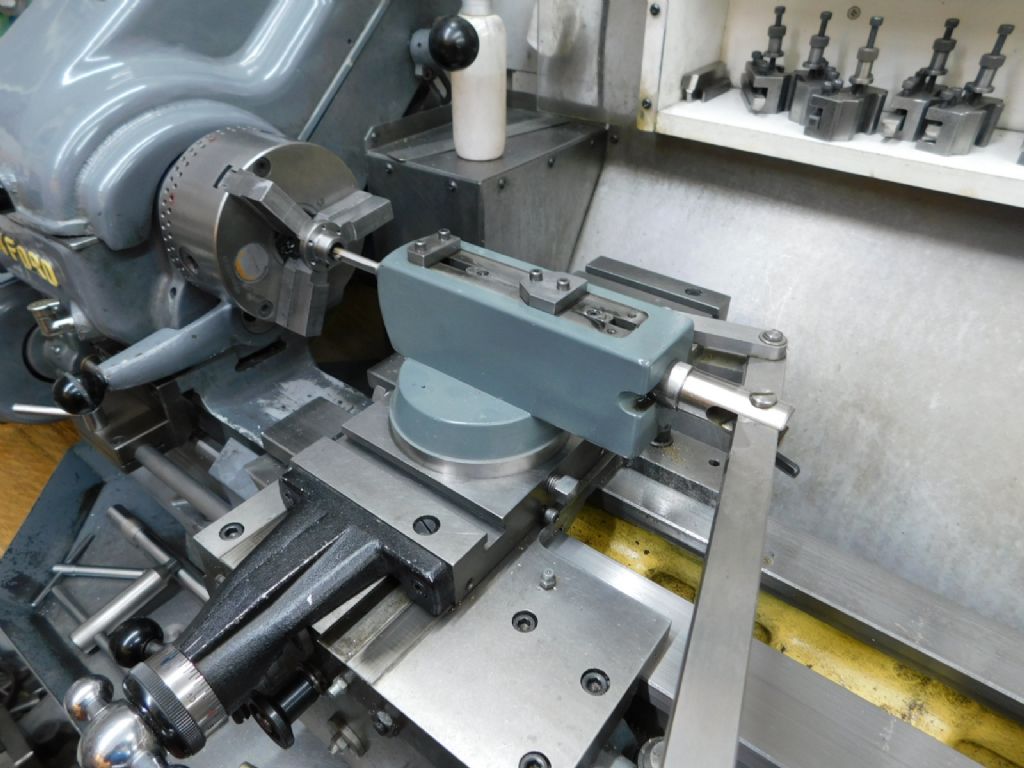
                                        The slot in the shaft for the key is obviously parallel and done on the milling machine or in the lathe if you have a cross slide milling attachment and can lock the spindle

                                        The keyway in the flywheel is for the most part and certainly in Doc's case likely to be cut using the lathe as a shaper. The only difficult part about that is A, to accurately shape a cutter of the desired width and B, to position it dead on centre line. The spindle does need to be held from rotating and he best way to do that without a purpose made spindle lock is to use the lowest back gear.

                                        Getting the two keys at the same angular position however without a positive dividing device on both is flying on the seat of your pants – as said before personally I'd put this to one side – idealism is one thing reality is another but as always it's about choice. It's a lot of 'accuracy requirement' for little or no positive effect save for the satisfaction of trying and possibly some scale effect.

                                        I made a slotting head for the Super 7 that can be set to cut a tapered keyway but have never had to use it in that fashion save once on the Bentley but that was at an angle on a tapered surface.

                                        Here it is being used last week on the couplings referred to

                                        marine compound (66).jpg

                                        There is still the difficulty of grinding the tool bit (by hand) to the right dimension at the same time as keeping it equal about the tool bit diameter but for a one off this could be milled in silver steel with far more accuracy.

                                        marine compound (67).jpg

                                        marine compound (68).jpg

                                        Despite being very careful in slotting the shaft the slots were slightly oversize so a stepped 2-2.15mm key had to be made at one end and slightly less at the other

                                        Broaches are fine – if you have them and the means to use them but they still don't cut a key on a taper – not that that is necessary as explained above and confirmed by Jason's comments – the key, from one side only, will induce tilt no matter how good the fit of flywheel to shaft. If you really want a tapered key as you show – to tighten the wheel to the shaft – then you need to do one at each side

                                        The flywheel just has to go round and round – it isn't going to have to drive anything but it doesn't want to move radially (rock) on the key – getting one to fit just right is a task on it's own – two at 120 degrees is just making things (very) difficult for yourself.

                                        But, as always, choice is choice and yours alone to make smiley


                                        Ramon


                                        PS Jason – Doc's ML7 has a 65T bull wheel so can't be used. The only option on a 7 is a dividing attachment in the rear of the spindle. Personally I would not rely on using the jaws to get the accuracy to match that of the dividing head (RT) used to mill the shaft

                                        Edited By Ramon Wilson on 09/08/2022 08:34:13

                                        #608823
                                        JasonB
                                        Moderator
                                          @jasonb

                                          Looks like TC used 6ba grub screws anyway so it's more a token taper key and likely just nips up at the thick end. the grub screw at the opposite end may go some way to applying opposite force to the wedging action and could be used to adjust any wobble that the one sided wedge will add.

                                          I have also remembered a third way that the taper can be cut in the flywheel, again using a broach but you stop the final pass short and the teeth of the broach leave a series of steps to the cut so the key has many points of contact across the whole width of the hub. Few hundred flywheels on engines built to order by Alyn foundry happily running that way without the flywheels falling off.

                                          If you did decide to by a cheap broach then the 120deg spacing is easily dealt with by using the same dividing head or rotary table to make your own bush with two slots at 120deg apart. Cut the first, fit a temporary key to stop the bush rotating and then cut the second.

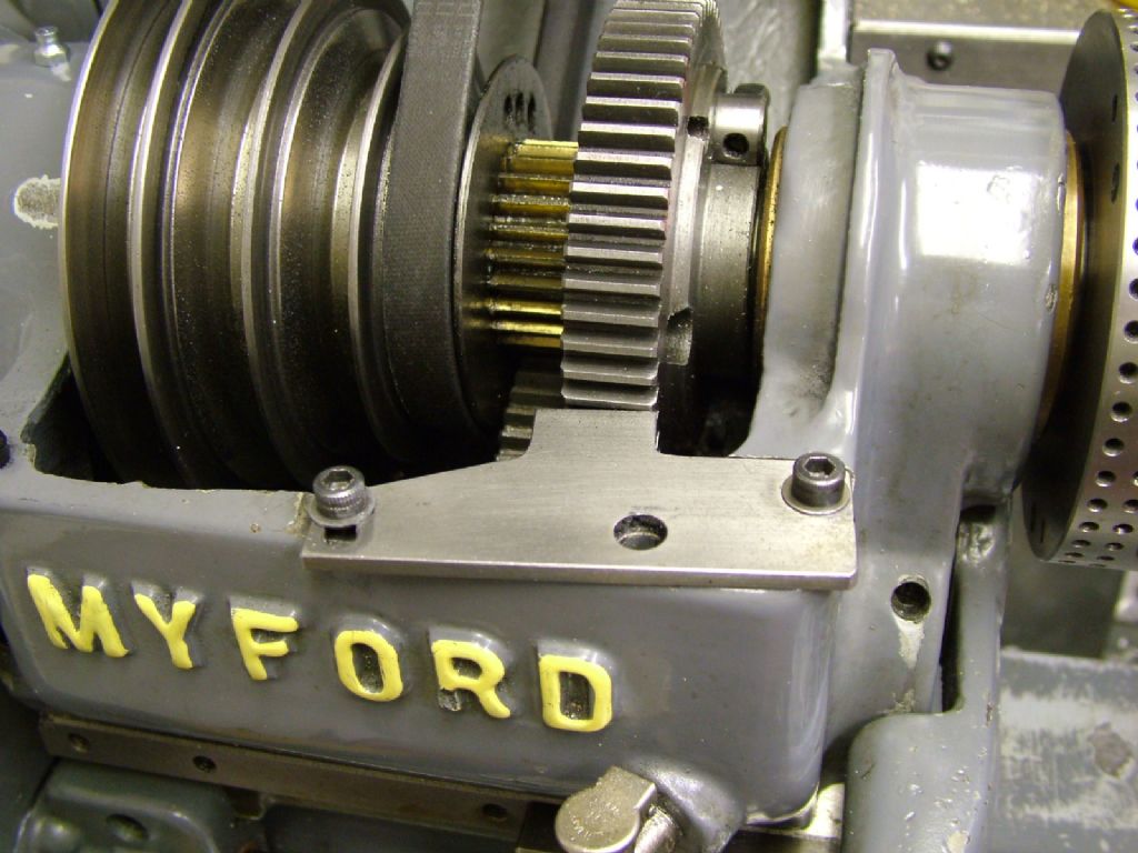
                                          Ramon I thought you could do it on the myford bull wheel, this one is said to be marked for 4, 6 and 10 divisions so the 6 would do for 120spacing?

                                          I can only go by what I have done using chuck jaws as the means to index the work, this was done using the 4-jaw and fits in all 4 positions, just used a simple spacer between bed and jaw. 3/16" wide slots in steel 1" long. I just used a 3/16" tool blank so no problems grinding to width, the 1/8" one on doc's model could be done with an 1/8" bit.

                                          #608825
                                          Ramon Wilson
                                          Participant
                                            @ramonwilson3

                                            Unless things have changed Jason I always thought the ML7 had a 65 tooth bull wheel – I believe there was something designed for it (New Zealand designer I think, name escapes me) to enable division but not direct division. I think the image you show is a Super 7 which has a 60 tooth wheel – here is my set up. This could not be done on my previous ML7.

                                            dscf0484.jpg

                                            Well 'proof is in the pudding' as they say so I bow to your skill on the four keys – excellent work, in fact very crisp indeedyes

                                            To use the chuck jaws though, I'm sure you would agree, you need to have a positive stop for the jaw to impinge upon – and, unless exactly the right height to place the jaw dead horizontal, in the same position each time – and a means to hold it in contact whilst machining takes place. I think you'll find given the gap bed on a 7 you would not be able to stand a stop post directly under the jaw (may be wrong on that without checking) To my mind it would not take much deviation to create a lot of fitting issues but as you have proved, it can be done on your lathe.

                                            I'm not saying using the chuck jaws is not viable just that it's not necessarily an ideal way to go about it generally

                                            Best – R

                                            Edited By Ramon Wilson on 09/08/2022 09:53:55

                                            #608962
                                            Paul Kemp
                                            Participant
                                              @paulkemp46892

                                              Ramon / Jason,

                                              A well fitted taper key should not “tilt” the flywheel on the crank if there is a little clearance. As long as the taper on the key matches the taper in the flywheel it acts to accumulate any clearance on the side of the shaft where the key is located pulling the other side uniformly against the shaft. A grub screw on a parallel key unless it is located in the centre of the length of the key is more likely to tilt the wheel.

                                              “Broaches are fine – if you have them and the means to use them but they still don't cut a key on a taper – not that that is necessary as explained above and confirmed by Jason's comments – the key, from one side only, will induce tilt no matter how good the fit of flywheel to shaft. If you really want a tapered key as you show – to tighten the wheel to the shaft – then you need to do one at each side“

                                              The flywheel on my half size TE is around 16” diameter from memory, it is a sliding fit on the crank so there is minimal clearance (I needed to be able to get it on easily) and it was machined bore and OD at one setting so it runs true. When fitted to the crank and the single tapered key is driven home it has about a thou eccentricity and about half a thou “tilt”. Single taper keys are common in TE construction.

                                              For two keys at 120 degrees Jason has it, make your own bush tapered at the bottom for the broach slot and cut a second slot for a key at 120 degrees. Broach the first keyway, rotate bush, insert a key to locate and then broach the second. My crank has six splines on the end for sliding gears. The splines on the crank were cut on a Bridgeport with a dividing head. For the gears I made a bush as described above and rotated 6 times to cut the grooves with a broach. Needed a little hand fettling on the radius at the root of the splines and some polishing but the gears fit nicely in all six locations.

                                              Paul.

                                              #608975
                                              Dr_GMJN
                                              Participant
                                                @dr_gmjn

                                                Bit of progress – milled the sides and counterbores. Seemed to work ok, more room for everything:

                                                #608979
                                                Dr_GMJN
                                                Participant
                                                  @dr_gmjn

                                                  Guys – What is the issue with the ‘fake’ taper key causing flywheel wobble? As Jason said, the thick part of the wedge will just contact the top of the flywheel keyway along a line, without any outward load being applied, and the grub screw (which is angled to stop the key coming out) will stop lateral movement. The taper keys will still have a rectangular shear area, but approximately triangular contact faces.

                                                  If I make a tool from silver steel, can’t I machine it square (obviously with a cutting edge), centre drill it in the 4-jaw, and then harden it? I can then use the drilling to align the tool to a centre in the lathe spindle, ensuring it’s dead on the centreline of the hub.

                                                  Then cut the key, measure it’s width and replicate the width on the shaft by milling. Then make the keys to suit.

                                                  It’s not like me to simplify things, but I can’t see any huge issues? *

                                                  (* disclaimer – I’ve never done this before)

                                                  So what’s the issue?

                                                  #608992
                                                  JasonB
                                                  Moderator
                                                    @jasonb

                                                    There should not be much wrong with it as a bit of looking at the article shows, Ramon and myself were suggesting it would be harder to use a tapered key in a tapered keyway.

                                                    A taper key against a tapered keyway will act like a folding wedge and move the flywheel radially with no tilt but a minute amount of axial offset which will depend on fit of shaft in the bore, lets say half a thou at the most (should be a lot less) which you would not see the eccentricity of.

                                                    Of you have a tapered key against a plain keyway it will tend to push the side of the flywheel where the thick end of the keyway is away from the shaft, lets say the same half a thou. which with a bit of trig is probably about 5thou offset at the rim so 10thou total wobble which you will see.

                                                    As I said the grubscrew shown will have some jacking action as well as retaining the key so you should be able to reduce that wobble quite a bit.

                                                    The angle of the grub screw is actually so you can physically drill and tap the hole as you could not do it square on very easily without extending drill and tap but the closer to right angles to the shaft the better.

                                                    Yes you could mill silver steel or just use a 1/8" square HSS tool blank which would be even simpler with the added advantage that the flat face being gripped in the holder will ensure the cutting face is square on. Doing the slots with a 3/32" or 3mm cutter and then taking a bit more off the sides would get them to a matching width,

                                                    #608996
                                                    Ramon Wilson
                                                    Participant
                                                      @ramonwilson3

                                                      Paul,

                                                      A tapered key mating with a tapered slot will I agree not influence the plane of the flywheel but as previously said a tapered key in a parallel slot fitted tight enough sufficient to locate the flywheel firmly (and at one end only) will influence the flywheel rim if there is the slightest slack in the bore to shaft make up. If tapered keys were used in such a fashion three or four would be used. Jason's thought are the same as mine here it takes very little difference at the shaft to put the rim out of kilter perfectly witnessed when running of course.

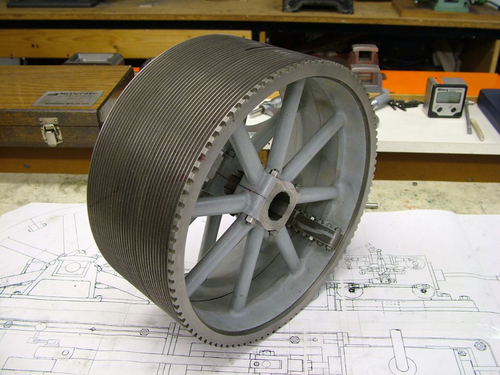
                                                      Broaching – again, as already said, is fine if you have the broaches and the means to apply them. Totally agree, if you make a broach guide at 120 degrees then the angular accuracy is readily attained. That is the way I broached this wheel. Though I made the guide at home I broached it using the broaches and broaching press at work. Not quite the same when you only have an ML7 to use.

                                                      Apologies for the bold – the means to underline text would be much better!

                                                      corliss project (28).jpg

                                                      Doc,

                                                      As mentioned previously, yes you can machine the tool bit from Sil St and it should do the job fine but just harden it, I wouldn't temper it. The tool needs backing off on all sides – particularly the width otherwise it will rub and wear as the slot deepens producing a key way with tapered sides! Definitely not what you want.

                                                      This op on a lathe is one that has to be done slowly, even with a one thou cut, the force require is considerable. Again on an ML7 with that small saddle wheel as a driving force a huge difference from a Marlco broaching set up – and a larger lathe of course. The wider the key the more force required. Jason's idea of roughing first is one way of getting round this but to my mind at no more than 3mm wide it's best done in one hit.

                                                      The tool/ toolbit holder needs to be short and reasonably substantial if flexing is not to occur. That will produce a tapered key way of unknown angle.

                                                      It’s not like me to simplify things, but I can’t see any huge issues? *

                                                      (* disclaimer – I’ve never done this before)

                                                      This is not a difficult op Doc but it has many potentials for slight error that will be only too obvious when fitting the key(s)

                                                    Viewing 25 posts - 701 through 725 (of 1,260 total)
                                                    • Please log in to reply to this topic. Registering is free and easy using the links on the menu at the top of this page.

                                                    Advert

                                                    Latest Replies

                                                    Viewing 25 topics - 1 through 25 (of 25 total)
                                                    Viewing 25 topics - 1 through 25 (of 25 total)

                                                    View full reply list.

                                                    Advert

                                                    Newsletter Sign-up